DONATION DRIVE - SUPPORT MSW - DO YOUR PART TO KEEP THIS GREAT FORUM GOING!
×

popeye2sea
-
Posts
1,935 -
Joined
-
Last visited
Content Type
Profiles
Forums
Gallery
Events
Everything posted by popeye2sea
-
 Modern signal flags are made with a ring spliced into the top of the tack line, which runs through the tabling on the hoist of the flag and extends beyond the bottom of the flag, and a snap hook spliced into the bottom of the line. The snap hook also has a hole with a sharpened edge that takes the marline that can be used to make up the flag for breaking after running it aloft in a rolled bundle. If you look closely in the WWII flag bags (still used today) you will see that the flags are held in racks of "fingers" that have slots to hold the rings and snap hooks of the flags vertically. Each set of fingers holds two of the same flag. The flags are arranged in the flag bag grouped together by type and alphanumerically (letters, numeral flags, numeral pennants, special pennants, substitutes). In operation you have a flag bag operator and a man on the halyard uphaul. The halyard uphaul has a snap hook spliced in the end. The flag bag operator snaps the hook on to the first flag of the hoist and the up haul is hauled pulling the ring out of the fingers. While the flag is coming out of the bag the flag bag operator is snapping the hook from the first flag onto the ring of the second flag. This continues until the hoist is complete. The last flags snap hook is then hooked into the halyard downhaul and the hoist is the raised to the required height (at the dip which is halfway up, or close up which is fully raised to the yard arm). Depending on the ship you can fit a half dozen flags or more in a single hoist. Additional halyards are employed until the signal is complete. Signals are hoisted from outboard in. A well trained signal crew can raise a hoist of flags in seconds from receiving the coded signal. Regards, a USN Signalman
 -
Can you identify this feature? 19th century 1st Rates
popeye2sea replied to Martocticvs's topic in Nautical/Naval History
Just a thought along the lines of mooring lines. You will find that ships, especially ones with high freeboard, place mooring line chocks on the hull closer to the water line. Sometimes they are set into the hull, other times they are mounted in a sort of blister. Perhaps? Henry -
Probably. You see the red sails mostly on coasters and fishing vessels. I doubt it would be used too much for naval vessels. Regards,
-
Barking or Tan Barking of sails produces the color you see in the photo. It was done in order to give more longevity to the sails, but it was generally deemed to be too expensive to do on larger vessels with a lot of canvas. Regards,
-
Could it be that what we are looking at here is a misrepresentation of several lines leading down to the same area? I can picture the shrouds being set up with blocks instead of deadeyes, but could the rigging plan designer be confusing fixed runners from other lines, i.e. halyards? These would lead up inside the shrouds and communicate with tackles on the opposite rail. Just a thought. Regards,
-
Dropping an anchor from a ships boat is one thing, but there is no way the crew of a boat is going to be able to weigh or raise an anchor. After all, the job did require a windlass or capstan on the main vessel to accomplish. As far as dropping one anchor and then maneuvering to drop another goes, the ship, at the end of her anchor rode was certainly less mobile but not immobile. There was considerable ability to warp the ship to any location within its anchor circle. The more anchors you put out, however the less maneuverable the ship becomes. The submarine rescue ship that I served in did exactly this when we set out a "4-point moor" (four anchors, one from each bow and one from each quarter in an X pattern). By hauling on one or more of the anchor cables we could position the ship over the downed sub in order to lower a diving bell. Granted a ship under sail is not as maneuverable as one under power, but it can still be done. Regards,
-
rail function
popeye2sea replied to MESSIS's topic in Discussion for a Ship's Deck Furniture, Guns, boats and other Fittings
My guess is that it is a fashion piece at the end of the top rail. It is not exactly clear on this drawing which is inboard and which is outboard. But there is a gangway and a couple of ladders there. Above one ladder at the end of the cap rail has plain stanchions and above the other ladder is a timber head. Is there a companion ladder on the outside of the hull that comes up to this point. It is also interesting how the perspective changes for the hammock cranes at this point. -
On many locomotive boilers there was not a sight glass, but a set of three valves aligned vertically. If you open the top one and got water the boiler was full. If you got air or steam them you had to add water. You could roughly check the level of water by cracking open one or another valve. Regards,
-
How are sails fixed to yards?
popeye2sea replied to Louie da fly's topic in Masting, rigging and sails
The method of attaching the robands to the yard as well as the method of attaching them to the sail varied according to the time period and the size of the yard. Robands were generally fastened through grommets sewn into the head band just below the head rope two per sail cloth. Whichever method was employed to pass them around the yard or jack stay they were finished with a simple square knot atop the yard. Regards -
Another name for the heel ropes used on the top mast and topgallant is a "top rope" Regards,
-
Ringtail boom in green at the bottom of the sail. Ringtail yard in yellow at the top. Regards
-
No clue what that line could be. It appears to have no function. The dashed line at the top could be indicating a leech line running before the sail (we appear to be looking at the aft side of the sail) Regards,
-
Like everything else aboard ship there are definite trends in the development of rigging. The steeve of the bowsprit initially was much greater and gradually became lower over time. At first the bowsprit was intended and used to rig bowlines to and so it needed to be very high to give a proper lead to those lines. It started to become more of a supporting structure for the fore mast, and so longer, when additional sections were added to the fore mast to increase sail area, but it still retained it's high angle. Next the spritsail top mast was added to increase head sail area and the bowsprit steeve started to come down. Additional lowering of the steeve of the bowsprit was done to increase the head sail area when stay sails and jib sails were added following the era of spritsail topsails. I believe that most of the changes that occurred were due to trial and error on the part of shipwrights and captains and only adopted generally when shown to give some advantage in real world use. For example, the spritsail topsail was eliminated because it proved to be too cumbersome and useless on most points of sail and the benefits derived from it were able to be provided by triangular stay sails and jibs. Regards
-
cable laid vs rope (left vs right twist)
popeye2sea replied to davec's topic in Masting, rigging and sails
Yes -
I remember building this kit back in the day. I have no idea what happened to the model. Regards,
-
The only thing I can definitely say about vacu-formed sails is that you should glue a bolt rope in all around. If you try to make holes in them to add robands, hanks, blocks, rigging, etc. they will rip and pull out. The bolt rope will allow you to fasten all these items to it without tearing your sail. If your feeling very ambitious you can fashion the bolt rope into the various cringles needed to attach sheets, tacks, bowlines, buntlines, etc.. You can even run a line across at the reef bands in order to attach reef points. Regards,
-
This lead for the sheets seems kind of odd to me. If you had sails set here the clews would be pulled off in the direction of the shrouds. Not very efficient. Regards,
-
I have been doing some thinking on the subject of tack lines on the fore sail. It seems to me that the only tack line that would matter would be the one to windward holding the clew forward and down. The lead of this tack would be more up and down when on a wind and so should not foul any other lines. The lee tack would be slack. The way I would solve the the fair lead problem would be to look at the where the clew of the fore sail would come to when braced up hard, and run the tack in the manner that reduces fouling and chafe to a minimum in this position. Regards,
-
Just to bring it all home to your rigging plan, the studdingsail booms are part numbers 165, 167, and 169. Regards
-
I find that taping and masking are more of a nuisance than they are worth and I always end up having to go back and fix stuff anyway. I get a much better result with just controlling the flow of paint off the brush. I never mask anymore. Regards,
- 2,699 replies
-
- 3
-

-
- heller
- soleil royal
- (and 9 more)
-
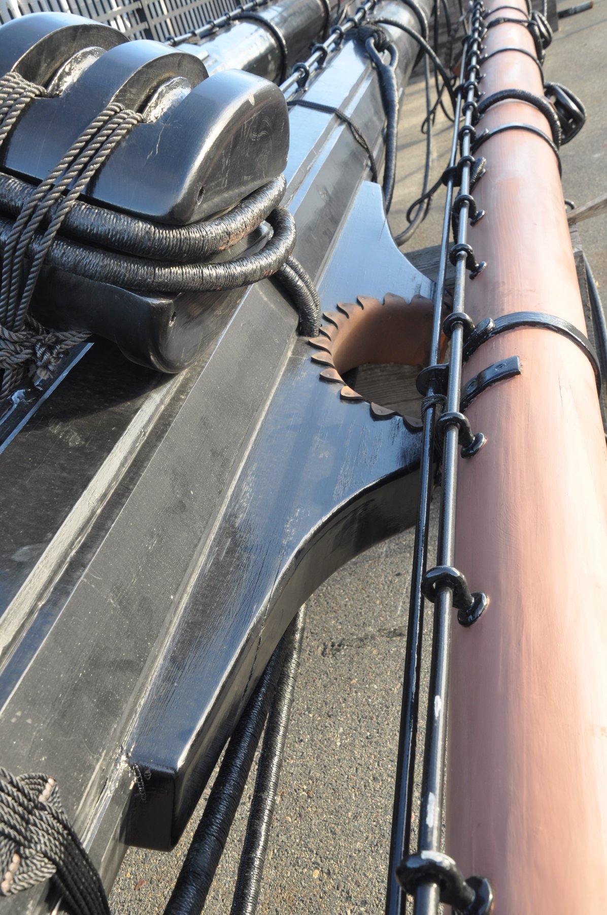
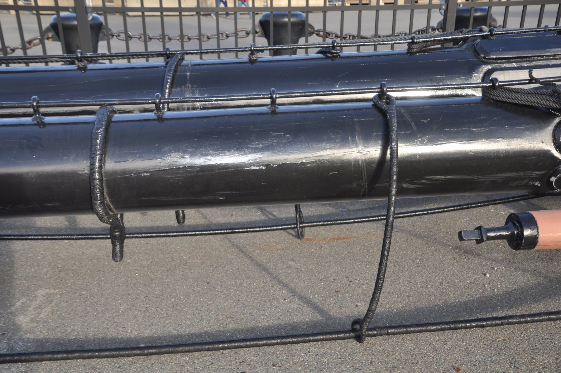
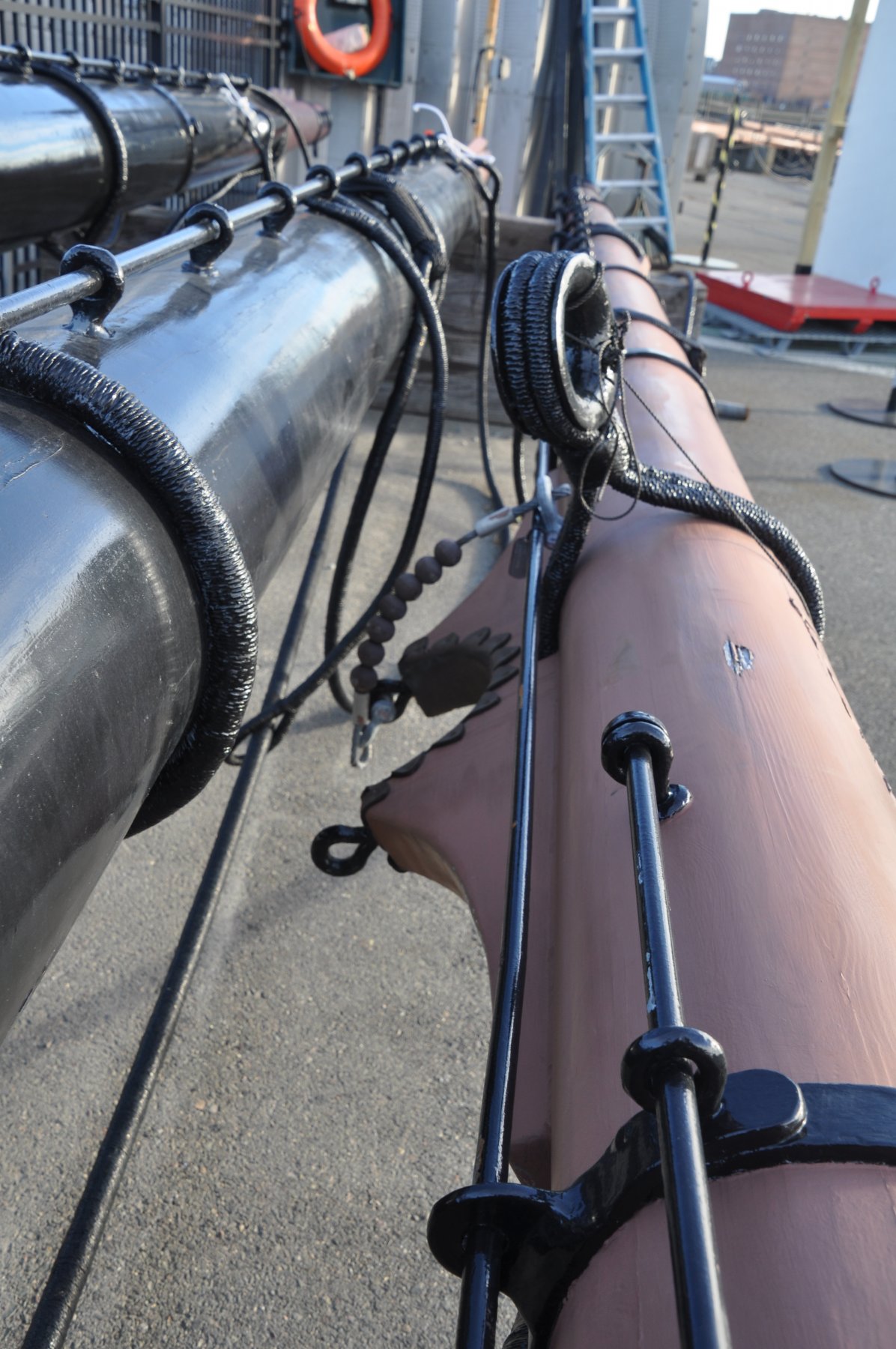
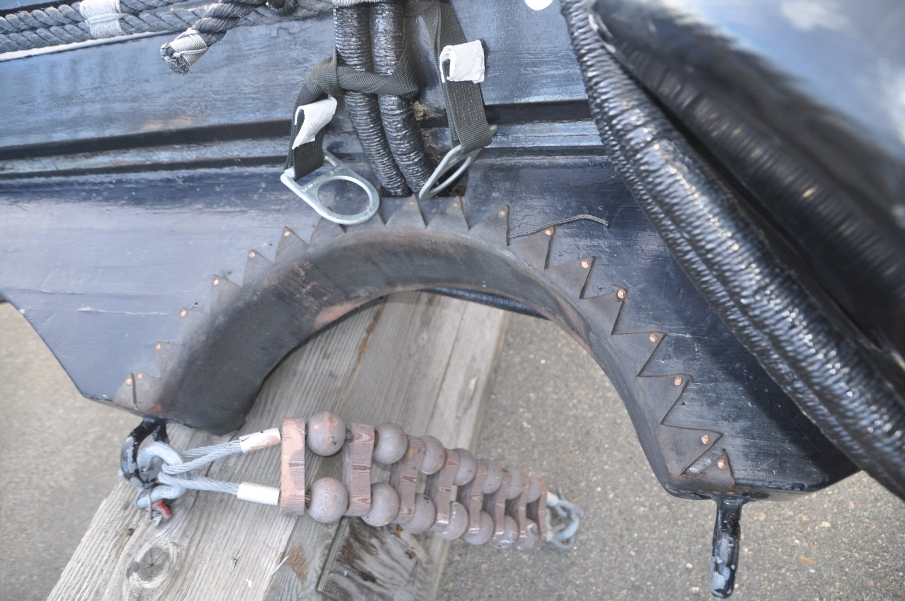
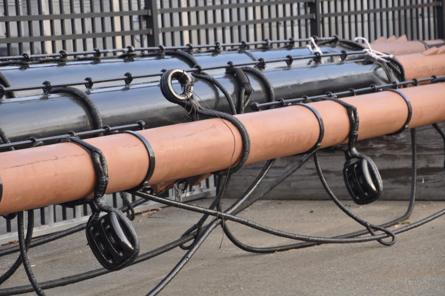
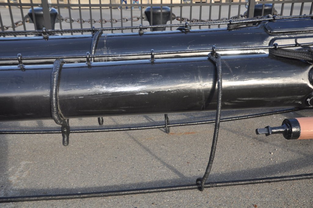
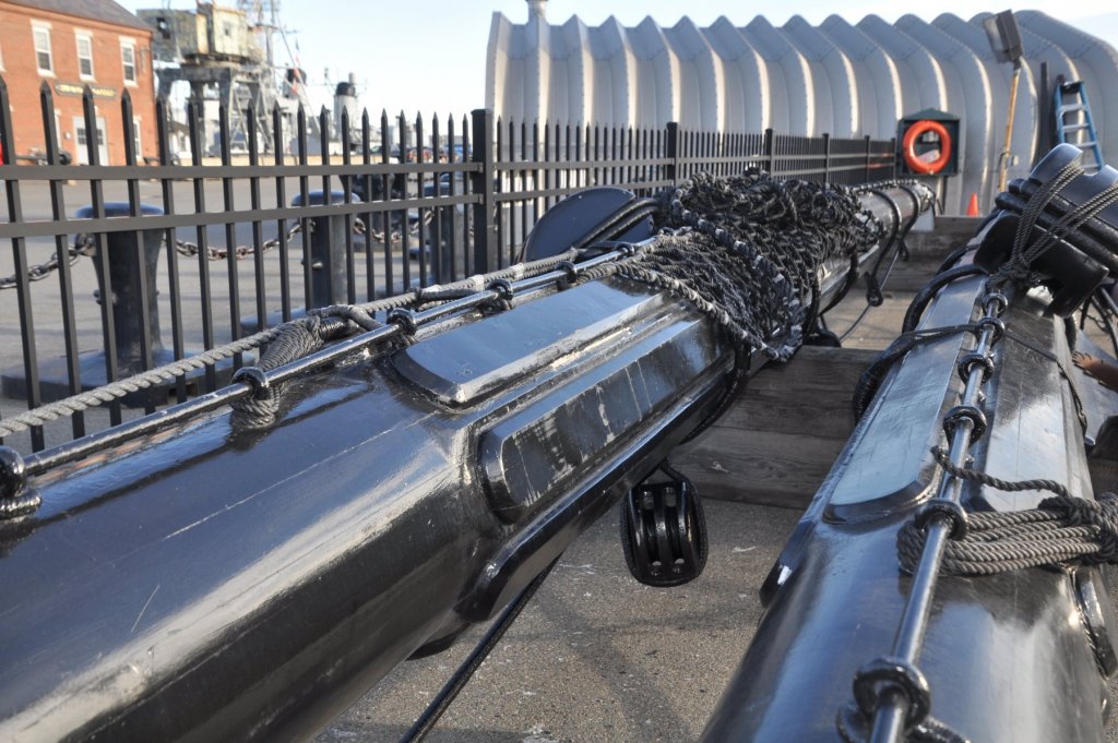
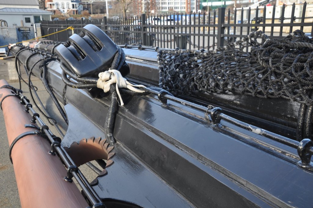
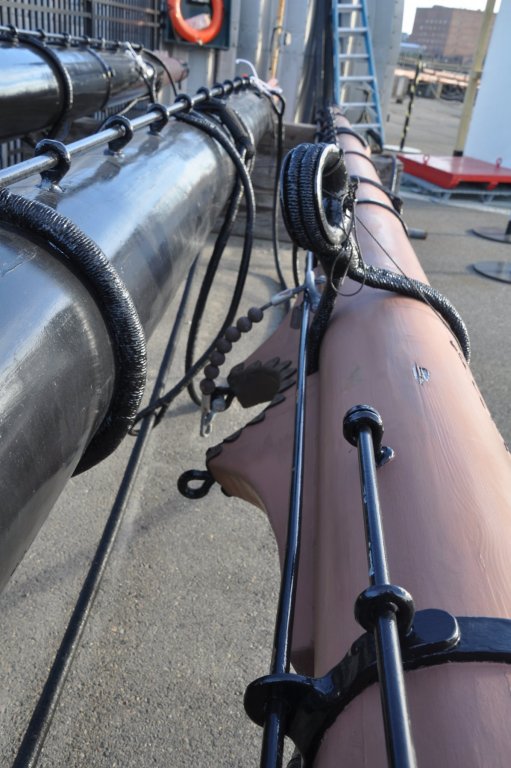
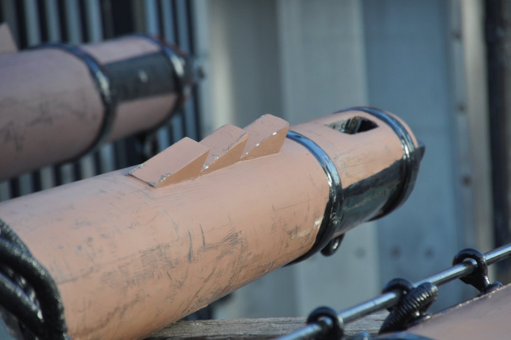
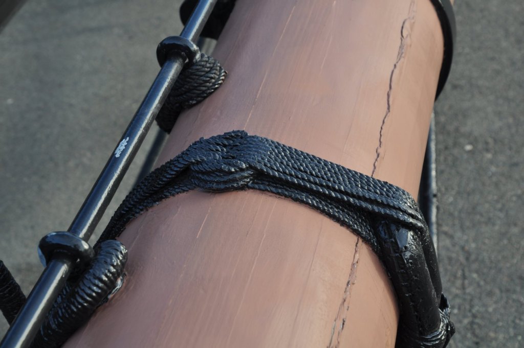
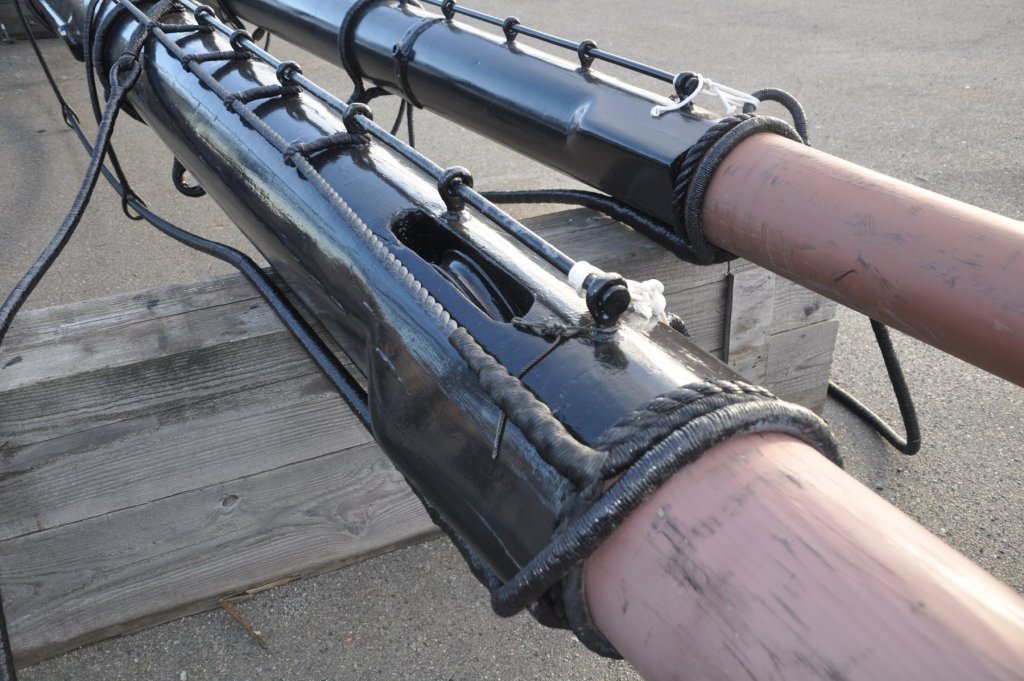
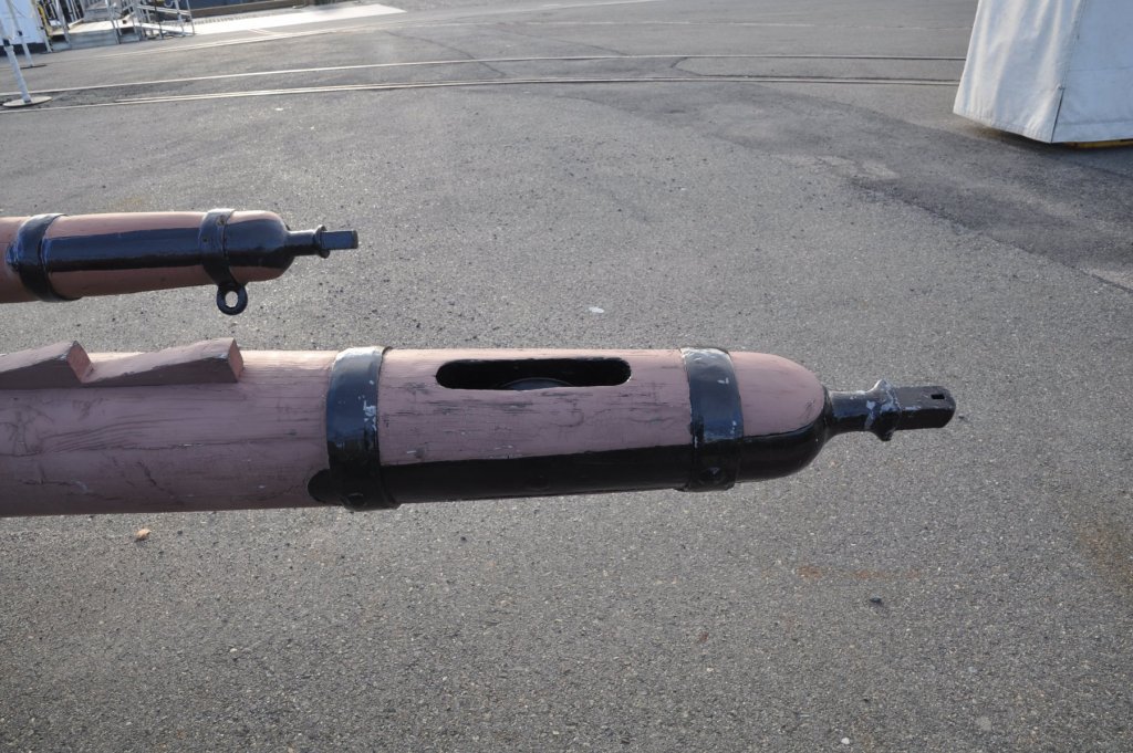
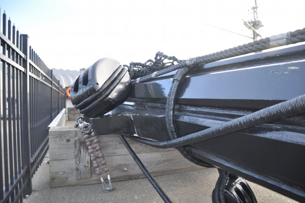
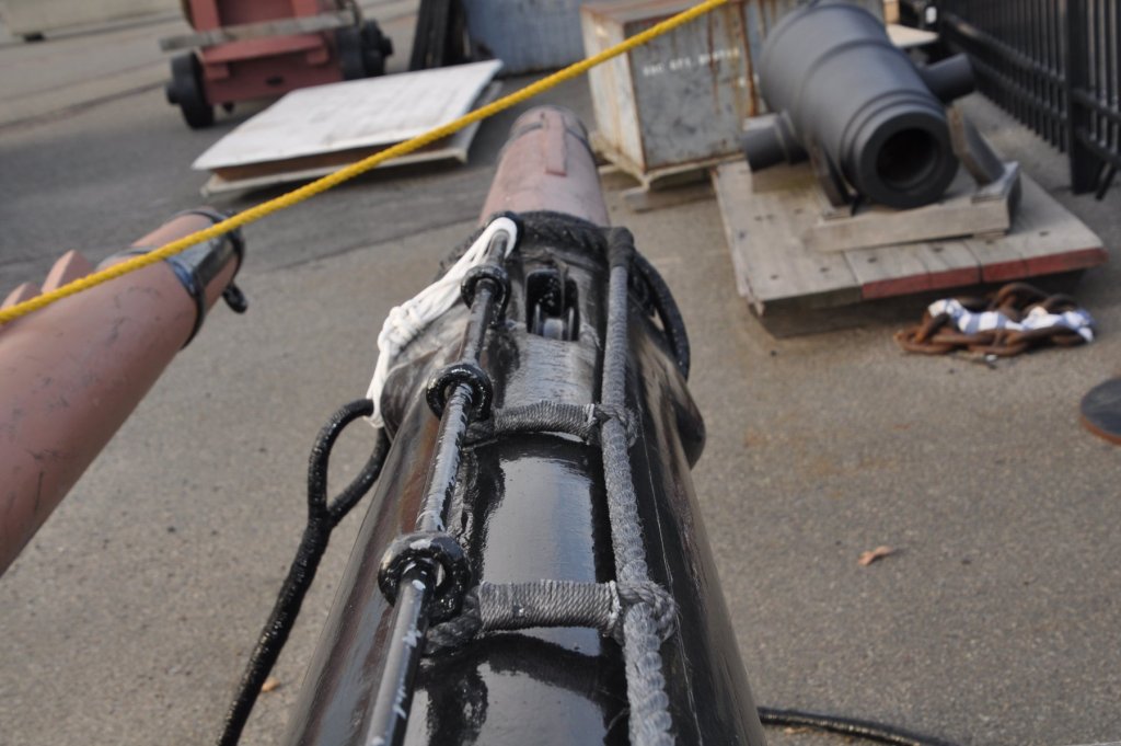
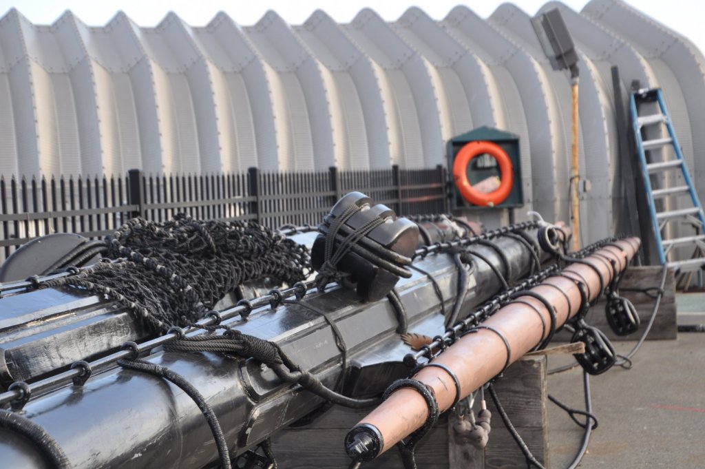
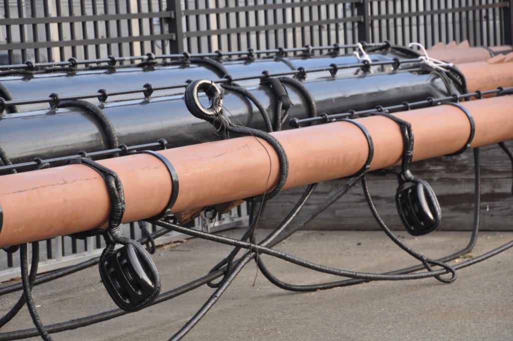
I've got some pictures to show you of the Constitutions topsail, topgallant, and royal yards. Hopefully you can see the fittings for the yoke and parrel arrangement. Also shown are the yardarm cleats and fittings for the outer studdingsail boom irons, as well as the sheaves for the sheets. The horses and stirrups are attached to the yards. At the center of the yards you can see the additional wood padding out the center section with the halliard blocks. There are no quarter cleats on the front of the yards. On the top mast yard, in addition to the iron jackstays there seems to be another rope one. Not sure what the purpose for this rope stay is. Perhaps it is for use as a man rope or hand hold for working aloft. This is the only sail that currently gets set on the ship. Also seen in the center section of the topsail yard is the net-like bunt gasket. Hanging from underneath the yards are additional blocks with their rose lashings above. I hope you find these useful. Regards,


- 19 replies
-
- 10
-
-
Superb work! I love the way it looks, but man! your going to have a heck of a job painting all of that. I know how long it took me to paint the considerably fewer decorations on the original piece. My hats off to you, sir! Regards,
- 2,699 replies
-
- 1
-
-
- heller
- soleil royal
- (and 9 more)
-
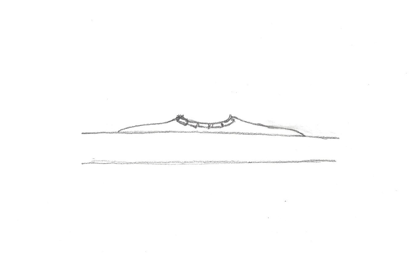
There is a fitting that looks something like this on every yard: This fitting both helps secure the yard to the mast an allows it to stand off the mast a bit. The surface that bears against the mast is leathered. I will look to see if I have any pictures of the yards to show the details of the yoke and cleats. Regards,

-
The fore topsail bowlines will lead from the sail forward to a pair of leading blocks on the fore topmast stay at about the level of the fore yard and then through two blocks attached to the bowsprit somewhere near the the collar of the fore stay. They then went directly to the forecastle rail or sometimes they went through the gammon block. Most often they belayed to the rail at the fo'c's'le or the "range" (a pin rail across the head). If to the range they sometimes went through an additional pair of blocks a little way up the fore stay. At times they were taken back up to blocks under the fore top and down to the deck from there. Regards, My apologies, I misread your post and gave you the info for the fore and not the main. The main topsail bowlines will run to leading blocks under the after ends of the fore trestle trees and then down to the deck. They will belay to whatever fitting you have abaft the foremast, whether that is set of bitts with a cross beam or a fife rail with belaying pins. I do not think there would be a separate set of bowline bitts.
-
What a superb job you have done with her. She looks fantastic.
- 1,350 replies
-
- 2
-
-
- constitution
- model shipways
- (and 1 more)