DONATION DRIVE - SUPPORT MSW - DO YOUR PART TO KEEP THIS GREAT FORUM GOING!
×

popeye2sea
-
Posts
1,935 -
Joined
-
Last visited
Content Type
Profiles
Forums
Gallery
Events
Everything posted by popeye2sea
-
 Surgery.... I have been posting on others build logs lately about the position of the halliard knight. It properly is offset from the centerline to give clearance for the main stay. It has been bothering me that the way the knight is installed on the Heller kit is exactly on center. I would feel like a hypocrite if I left it this way. So...I decided to remove the fore halliard knight and shift it approximately it's own width to starboard. The good thing is that I have not installed the fo'c's'le deck on the ship yet so I can still get at things from underneath. Removal of the knight was accomplished with an exacto blade scoring over the joints and wiggling the knight free. It came out with no damage. Then the mounting hole was widened and the deck piece that I cut out was fit into the old hole. Additional styrene strip was used to fill in the remaining gap and the joints were puttied with contour putty. The knight was mounted in it's new hole and some touch up paint completes the job. Pictures to follow... Regards,
- 196 replies
-
- 3
-

-
- plastic
- soleil royal
- (and 2 more)
-
And that is exactly why the knight is always offset from the centerline of the mast. In reality, that rams head block would need to travel almost to the trestle trees under the top when the lower yard was lowered. Regards,
-
It is my understanding that the top rope was always unrove once the top mast was hoisted and fidded into place. The end of the top rope had a hook spliced in and the top rope blocks were stropped with a hook in order to facilitate them being sent down. Regards,
-
Split Brass Ring Frustrations
popeye2sea replied to David Lester's topic in Masting, rigging and sails
Another trick to remember is to never open the ring by pulling the ends directly apart (in line with the ring). This deforms the ring out of round and it is hard to get the two ends to meet properly again when closed. Instead twist the ring open by spreading the ends perpendicular to the ring. When you close the ring back up the ends will be perfectly aligned and the ring will remain round. Regards, -
I think there may also be a difference in usage. For example: thimbles are stropped into the eye of a block in order to take a hook. A bullseye acts a sort of fairlead for rigging, or it can also be used like a heart. Regards,
-
You can take up the slack at the yard. Secure one leg of the tye to the yard with a cow hitch (like the end hitch for a ratline). Take the tye up over the cap and then down to the rams head block abaft the mast then back up on the other side and over the cap and thence to the yard. You should easily be able take up any slack in the tye while you are tying the second cow hitch. BTW the cow hitches should be backed up by seizing the end of each leg of the tie to its standing part just above the hitch. Regards,
-
Le Soleil Royal by Nek0 - 1/72 - Marc Yeu
popeye2sea replied to Nek0's topic in - Build logs for subjects built 1501 - 1750
You've never carved before? And you made your own carving tools? You have incredible natural talent and skills. I am in awe. I wish I had a fraction of your talent. Even your photography skills are great. Regards,- 208 replies
-
- 5
-
-
- le soleil royal
- 104 guns
- (and 2 more)
-
Marc, Thanks for looking in on my too long dormant build. It's hard to find time to work in the shipyard, lately. I have also been following your build with great interest. I'm looking forward to seeing the progress. I'm more of a rigging guy so the changes I have made to my builds hull are minimal. As if I have the time to do more stuff I have been mulling over the making of a pictorial history lesson about how the lower masts are raised and stepped as well as how the tops were swayed up into position. I thought it might be of some interest to a few of us nautical history buffs. Who knows....maybe someday. To your question on chesstrees; R.C Anderson gets into some of the details in his book The Rigging of Ships in the Days of the Spritsail Topmast. In which he suggests that French and Dutch vessels usually used a chesstree timber (fore and aft hole) up to about 1660. Afterwards the chesstree was a direct hole through the bulwark often ornamented as a lions head. Regards,
- 196 replies
-
- 2
-
-
- plastic
- soleil royal
- (and 2 more)
-
In haul tackles were used for these guns. Regards,
-
I just checked what is left of the kit in the basement and I believe I have all that you are looking for. Send me a pm with your address and I will forward the pieces to you. I am not sure sending the whole kit will be a good idea. It is very bulky and would be very expensive to ship. Regards,
- 2,699 replies
-
- 3
-
-
- heller
- soleil royal
- (and 9 more)
-
I have my first kit of SR still boxed up in my basement. The hull got warped somehow so I had to replace it. I ended up buying a whole new kit so I still have the mostly unbuilt original. I will have to check what condition it is in but you are more than welcome to whatever you may need. Regards,
- 2,699 replies
-
- 4
-
-
- heller
- soleil royal
- (and 9 more)
-
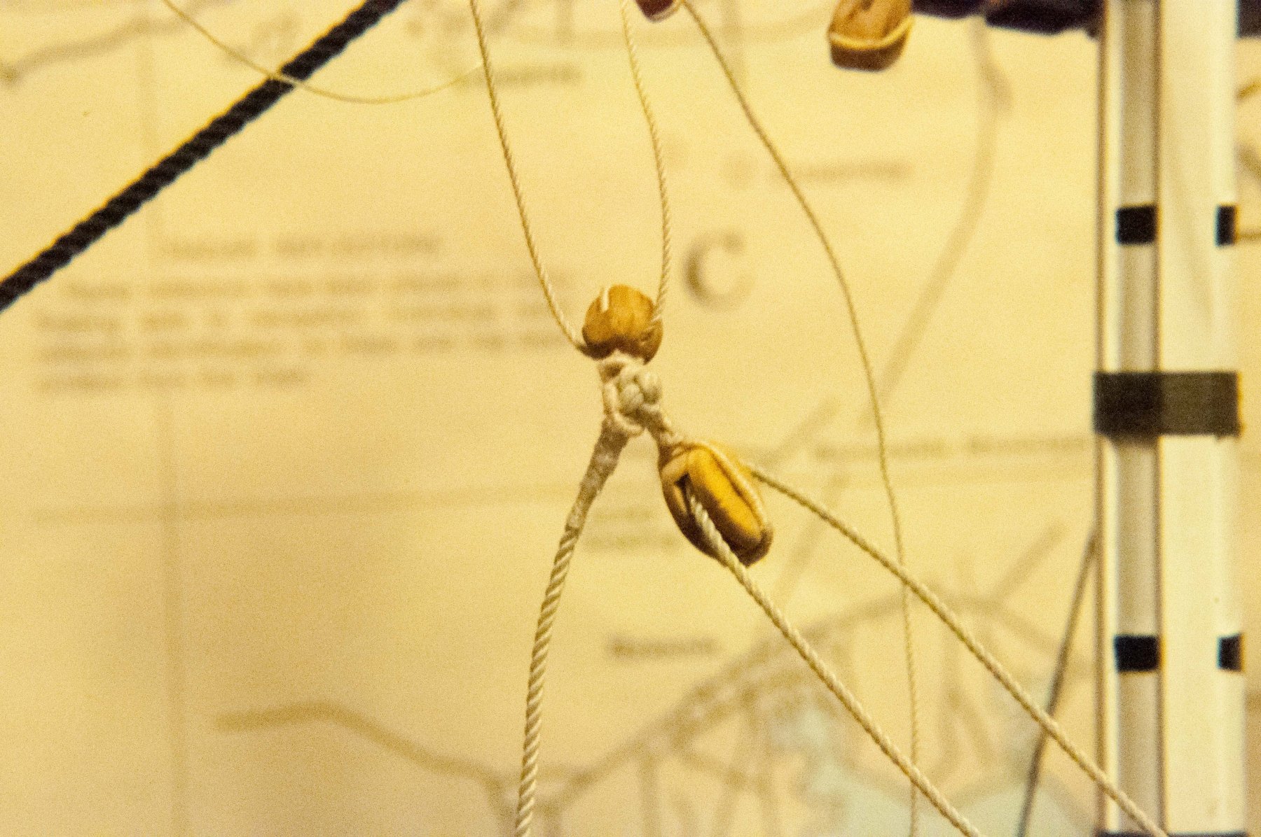
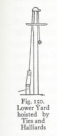
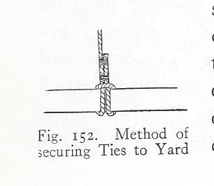
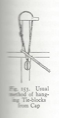
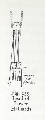
Here are some illustrations that may help a bit. The first shows an overview of the tie and halliard set up and the rest show some details. The lead of the tie over the cap, as in figure 150 was an early method used by the French and Dutch up to about 1700. Figure 153 shows a later variant where the tie leads through blocks hanging from the cap on pendants. The pendants hang inside the stay but outside the trestle trees. The English sometimes employed another variant with the ties leading through sheaves in the hounds. The tie starts secured near the middle of the yard as in figure 152 leads up over the cap, or through the tie block, down abaft the mast through a sheave or hole in the top of the rams head block (shown in figure 155) and back up on the other side of the mast where it passes over the cap and secures to the yard in the same manner as before. The halliard is reeved between the knight and the rams head block as in Figure 155. The tie should be about the thickness of the shrouds with the halliard about 2/3 of the tie.
-
As Dave has said it is a knight. And it typically has three or four sheaves let into it. The fourth or extra sheave not used for the halyard was for the top rope, which was used to raise the top masts into position. You will notice that the knight is offset from the center line of the mast. This is to insure that the main stay does not foul the halyard tackle. The halyard starts at a ring bolt set into the side of the knight, runs through the sheaves of the rams head block and the knight and then belays around the head of the knight. Regards,
-
It is not wrong. The ship is just equipped differently. She has a flagstaff on the tafferail. The general rule is the ships National Ensign will be flown aft of all the others. Specific locations of flags are determined by the configuration of the rig. And the protocol for a single masted vessel will necessarily be different from a three masted ship. Naval vessels flag protocols can get pretty complicated with respect to locations of host nation, command and visiting dignitary flags. You have to consult the publications to determine whose flag takes precedence in order to determine where to fly it. Regards,
-
The national ensign of the ships home port will be flown from the driver/spanker gaff if so equipped. The flag of the host nation or nation being visited will be flown from the fore or main truck. Regards,
-
Clueline, Tack and Sheet Question
popeye2sea replied to 6ohiocav's topic in Masting, rigging and sails
First, it helps to understand what each lines function is. The sheet, tack and clew lines all control the lower corner (or clew) of a square sail. The sheet hauls the lower corner aft. The tack hauls the lower corner forward and the clew line hoists the corner up to the yard for furling the sail. The fore sheet usually runs as you suggest, from an eyebolt well aft on the side through a single block at the sail then back through a hole or sheave let into the side and belays at a cleat or kevel on the inside of the rail or bulwark. The fore tack usually runs single and starts with a tack knot thrust through the clew of the sail. It runs forward through a single block seized to a short pole called a boomkin (or bumpkin) and then inboard to belay on a cleat or kevel inside of the rail. The boomkin helps to keep the foot of the fore sail fully extended. If you have no boomkin you can take the tack directly to the cleat. But it should not be too difficult to fit a boomkin if you wanted to add it in. The clew line starts about a third of the way out from the middle of the yard where it is fastened with a timber hitch. It then passes through a single block at the corner of the sail from outboard in then back up to a single block seized to the yard a little inboard from its standing end. From there it goes to the deck most often through additional leading blocks near the mast. When the sail is furled the clew line is hauled up. This has the effect of pulling the corner of the sail up towards where the clew line is fastened at the yard. That is why the tack, sheet and clew blocks are often depicted hanging near the center of the yard when no sails are present. BTW. As additional information the main tack, if it runs single (not through a block at the sail) will be the largest line of all of your sails running rigging. It's a good reference point to judge the thickness of all the rest of the sails running rigging. Regards, -
Considering that the paragraph states that the plans included are from 1794 - 2010 I'm not sure we can pin down a date !!!
- 742 replies
-
- 6
-
-
- constitution
- frigate
- (and 1 more)
-
They, and all the other modern fixtures like the iron bitts instead of the fore anchor bitt and the modification of the capstan to take chain and the water tank in the hold, were added by the Navy so that she could function to modern standards for safe navigation for her ( I think) 1927 tour of the country. I may be wrong as to which refit the changes can be attributed to. I believe most of her first century was with hemp cables. I
- 742 replies
-
- 6
-
-
- constitution
- frigate
- (and 1 more)
-
They are called chain stoppers. And their function is to stop the chain from paying out or slacking inadvertently. They are also used when letting go the anchor. Also when you need to stopper the chain in order to surge the nip over the windlass. They are on every Naval vessel to this day. Regards,
- 742 replies
-
- 9
-
-
- constitution
- frigate
- (and 1 more)
-
Show pictures of your work area
popeye2sea replied to a topic in Modeling tools and Workshop Equipment
Figured you were a chief. No one else would call their space a goat locker. Looking good, brother. Regards, SMC -
USS Constitution (Mamoli 1:93) What to do?
popeye2sea replied to Techsan's topic in Wood ship model kits
Looks like a fine job so far. Continue! Regards, -
The tack knot is a doubled wall and crown knot. If you just make a wall knot the ends of the strands end up on the wrong side of the knot. You want them to end up coming down against the rope where they can then be served over. The knot is not very easy to do in small scale. But it can be done. Regards,
-
Not familiar with the Enterprise. Square rigged fore sail? You are going to want enough clearance for that sail. Regards,
-
I would venture a guess that the location of the channel, or what would be the channel, is too low and would probably be located directly under the gun port. If you raise the location to that point a normal width channel should work. Regards,
-
I don't know why people go to books like Petersons to get information when there are more contemporary and much better sources of information out there. After reading something like Steels works or Falconers I pretty much shelved Petersons, never to be cracked open again.