HOLIDAY DONATION DRIVE - SUPPORT MSW - DO YOUR PART TO KEEP THIS GREAT FORUM GOING! (Only 72 donations so far out of 49,000 members - Can we at least get 100? C'mon guys!)
×
.JPG.ca33079f5815b861e67b9c2cccd37982.JPG)

Blue Ensign
-
Posts
4,564 -
Joined
-
Last visited
Content Type
Profiles
Forums
Gallery
Events
Everything posted by Blue Ensign
-
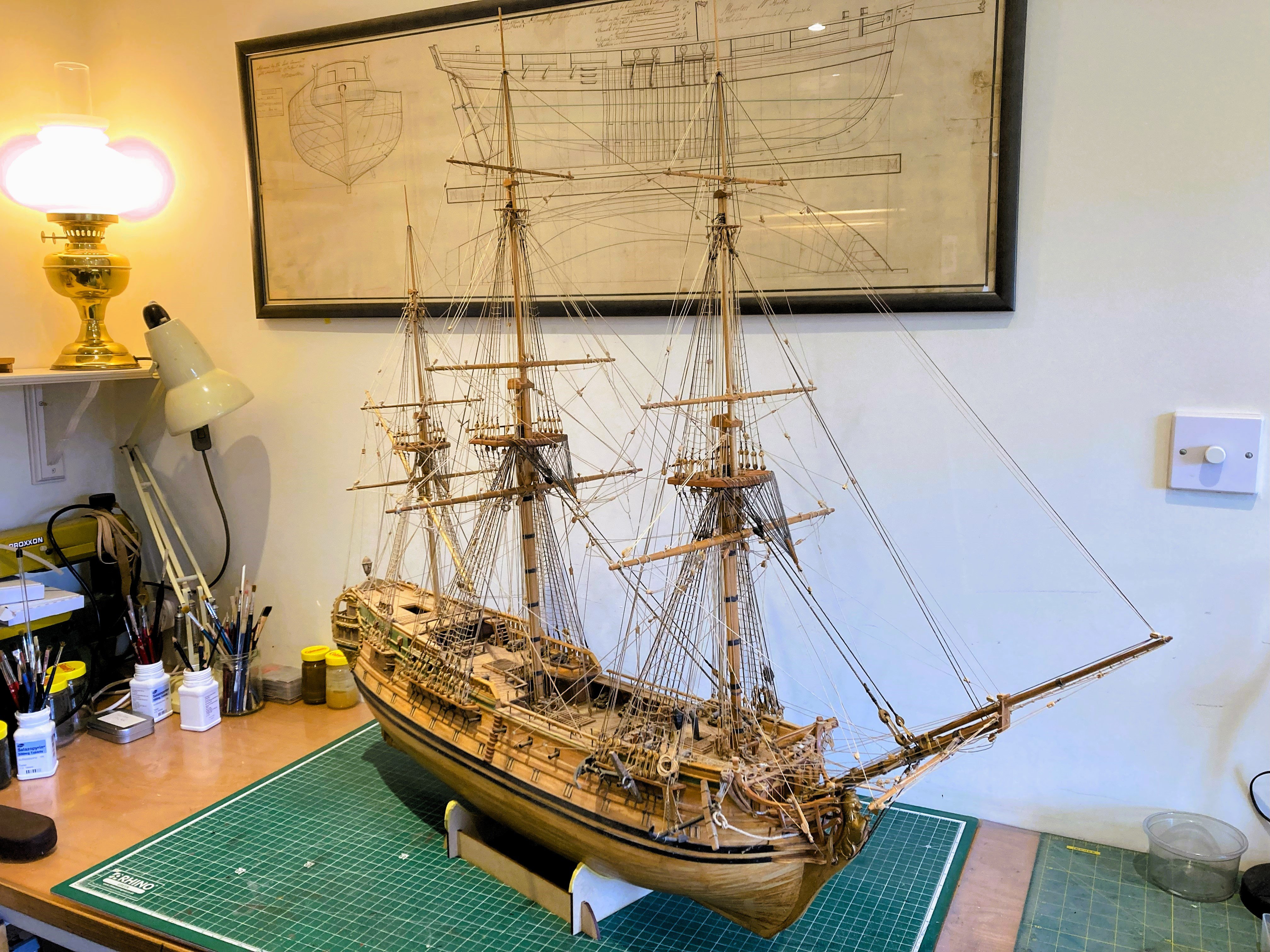
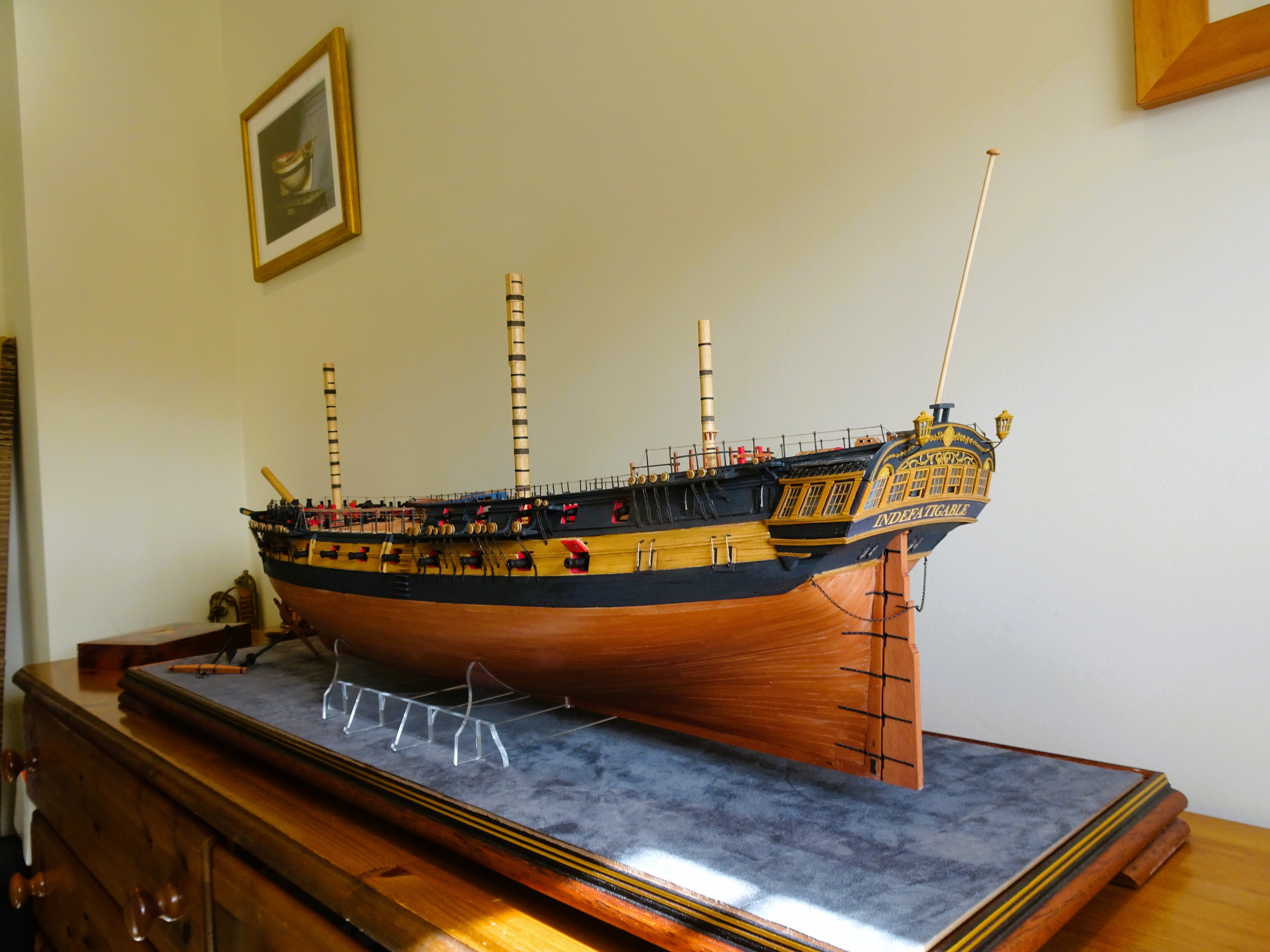
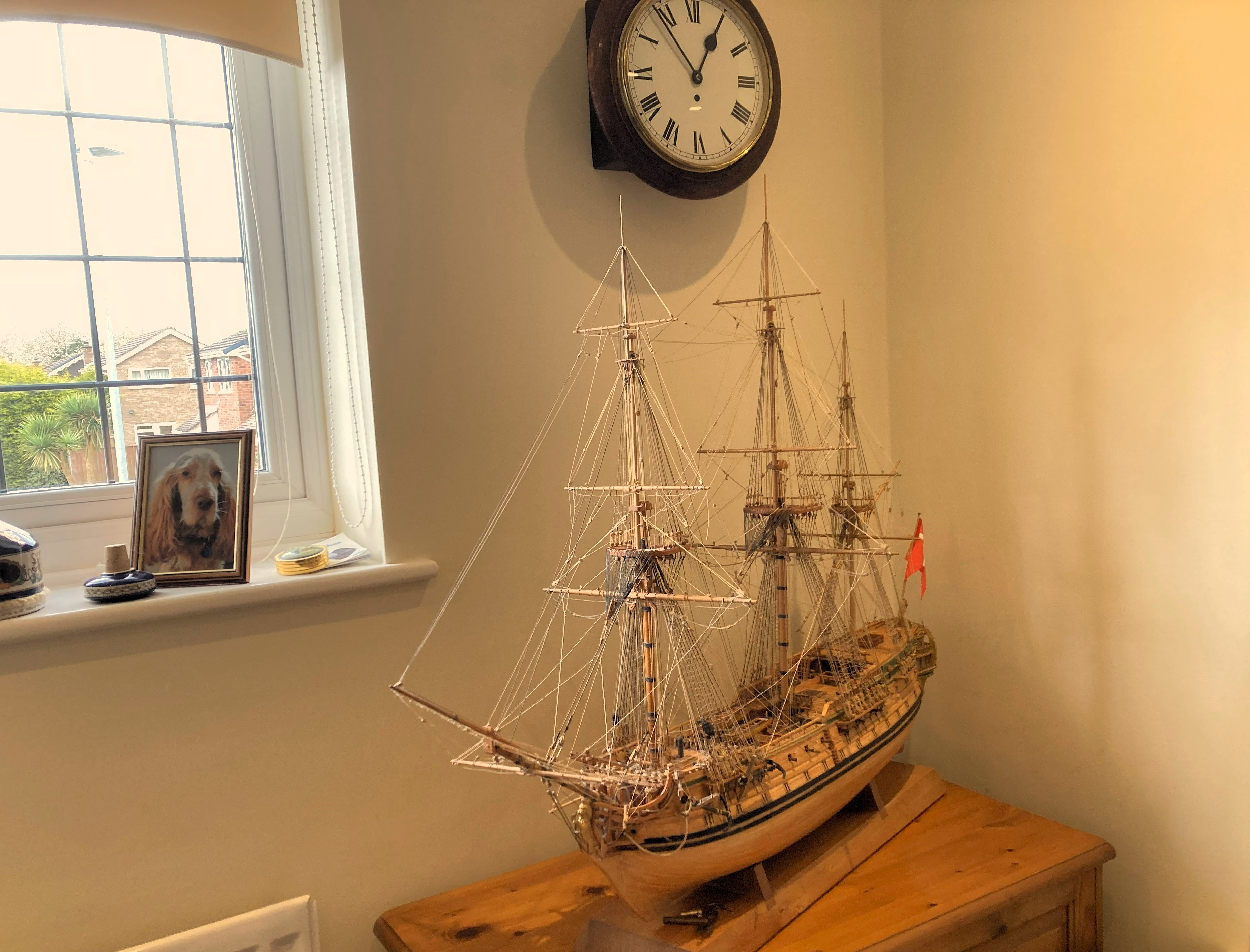
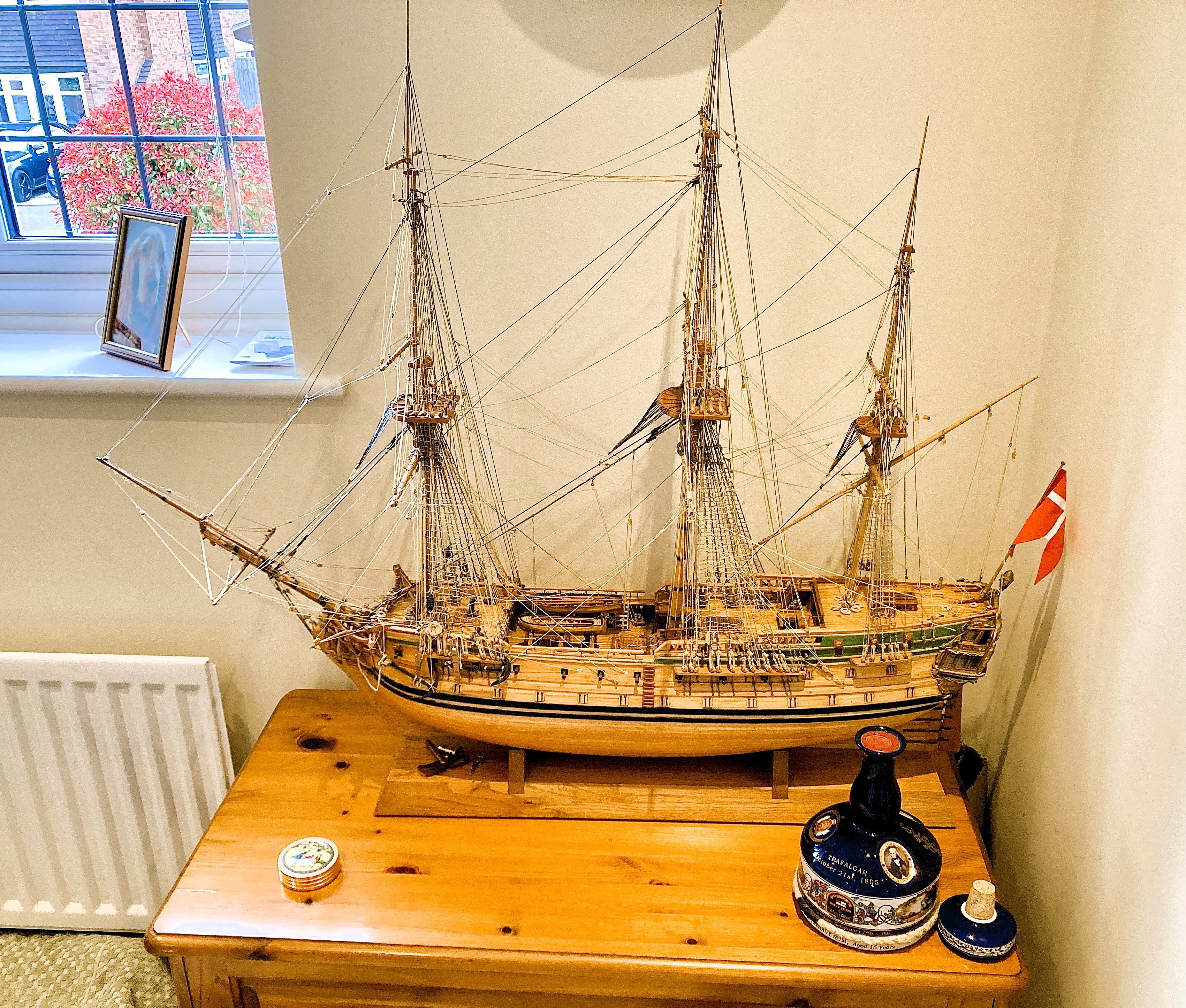
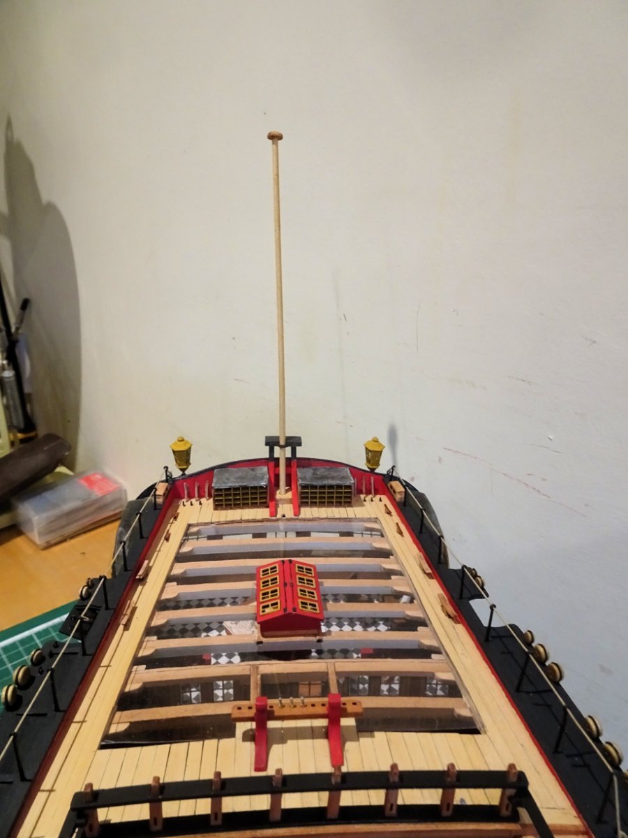
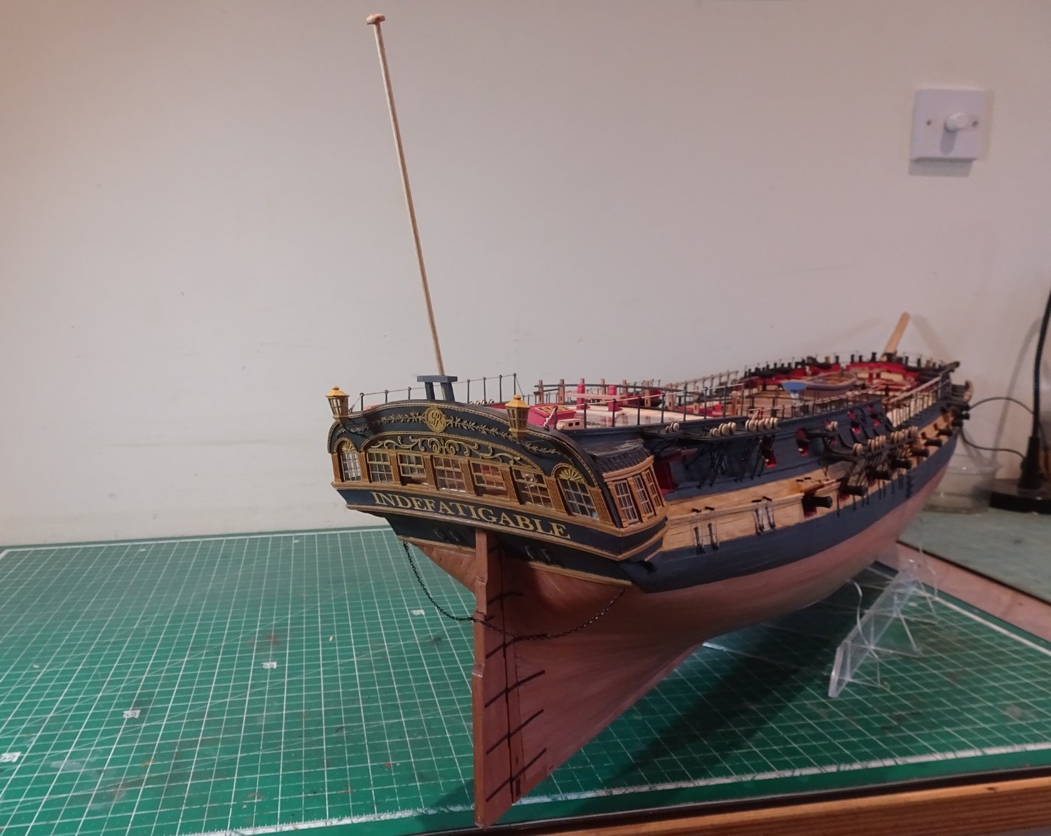
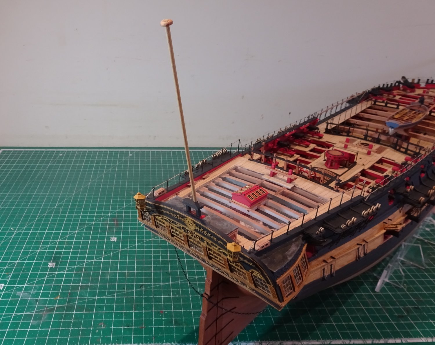
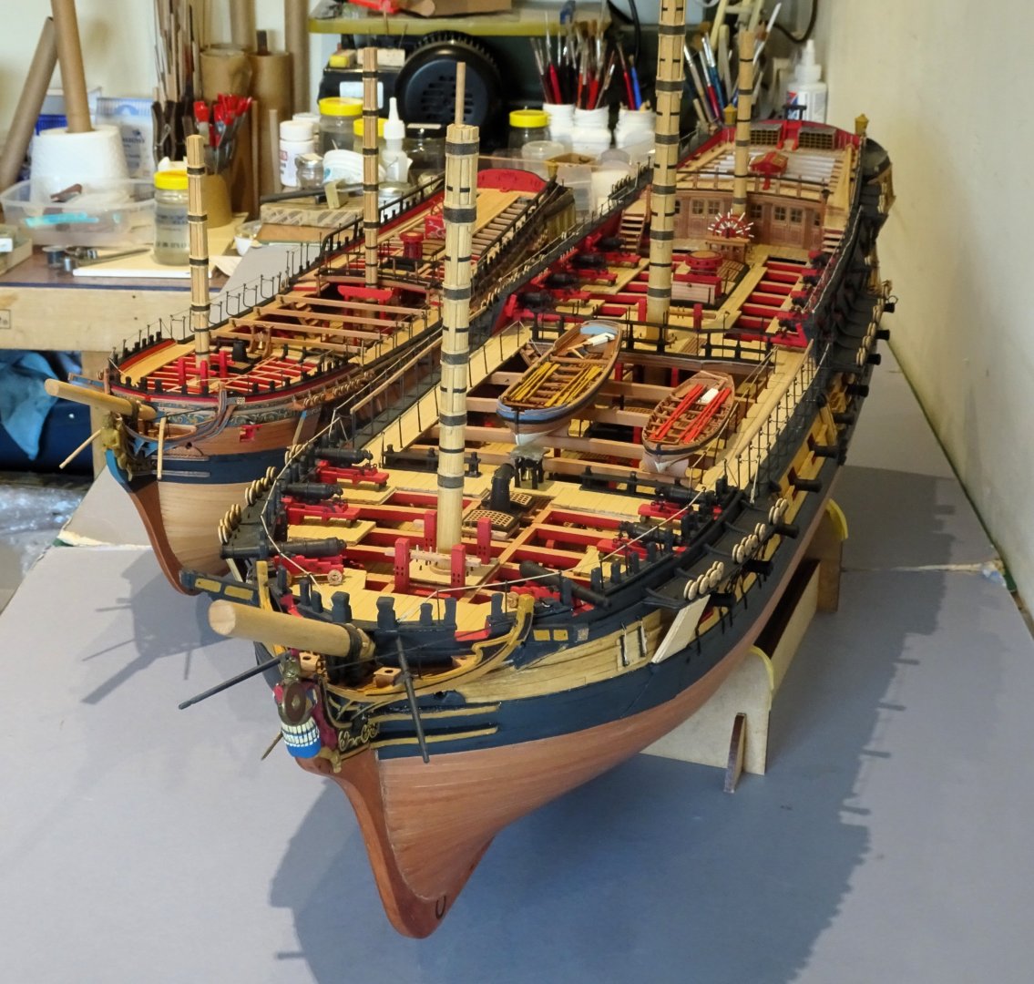
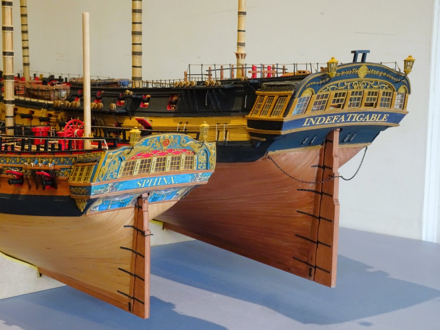
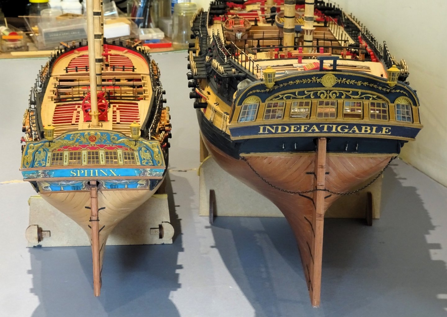
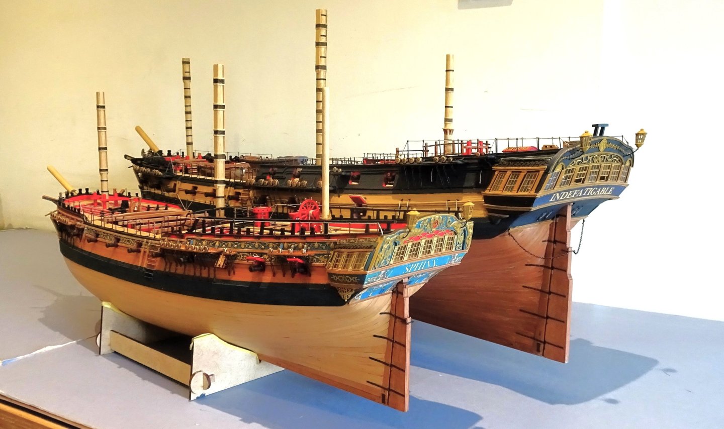
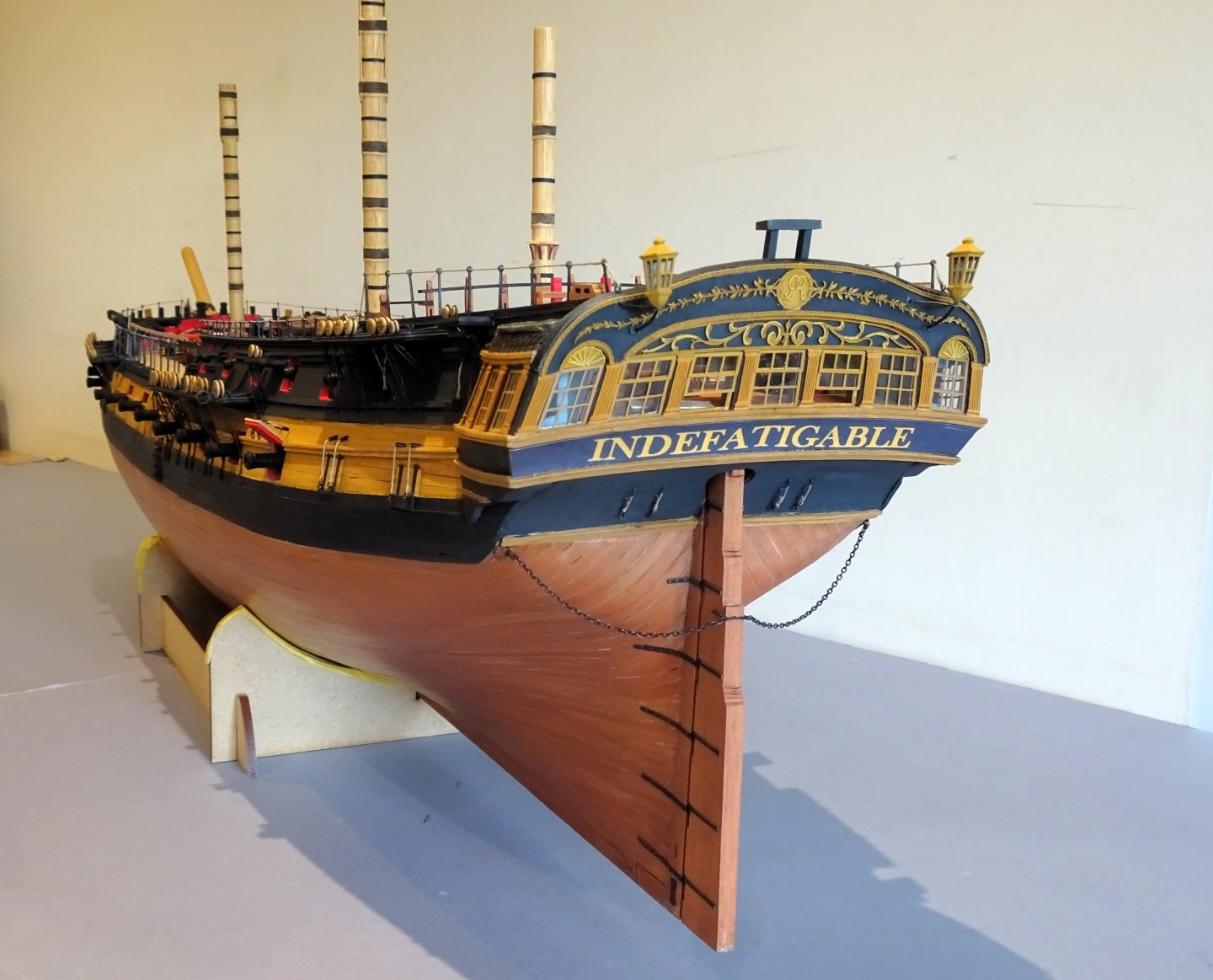
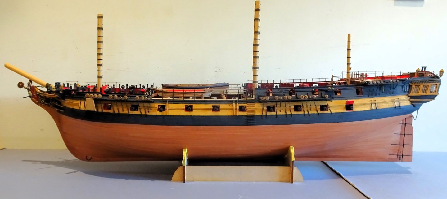
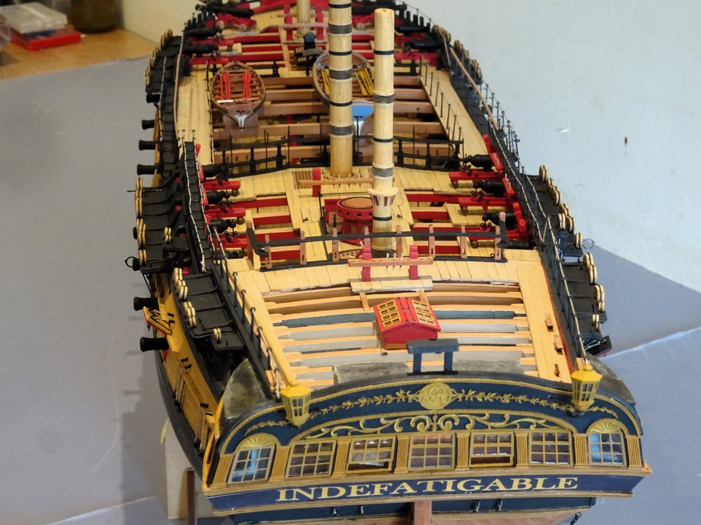
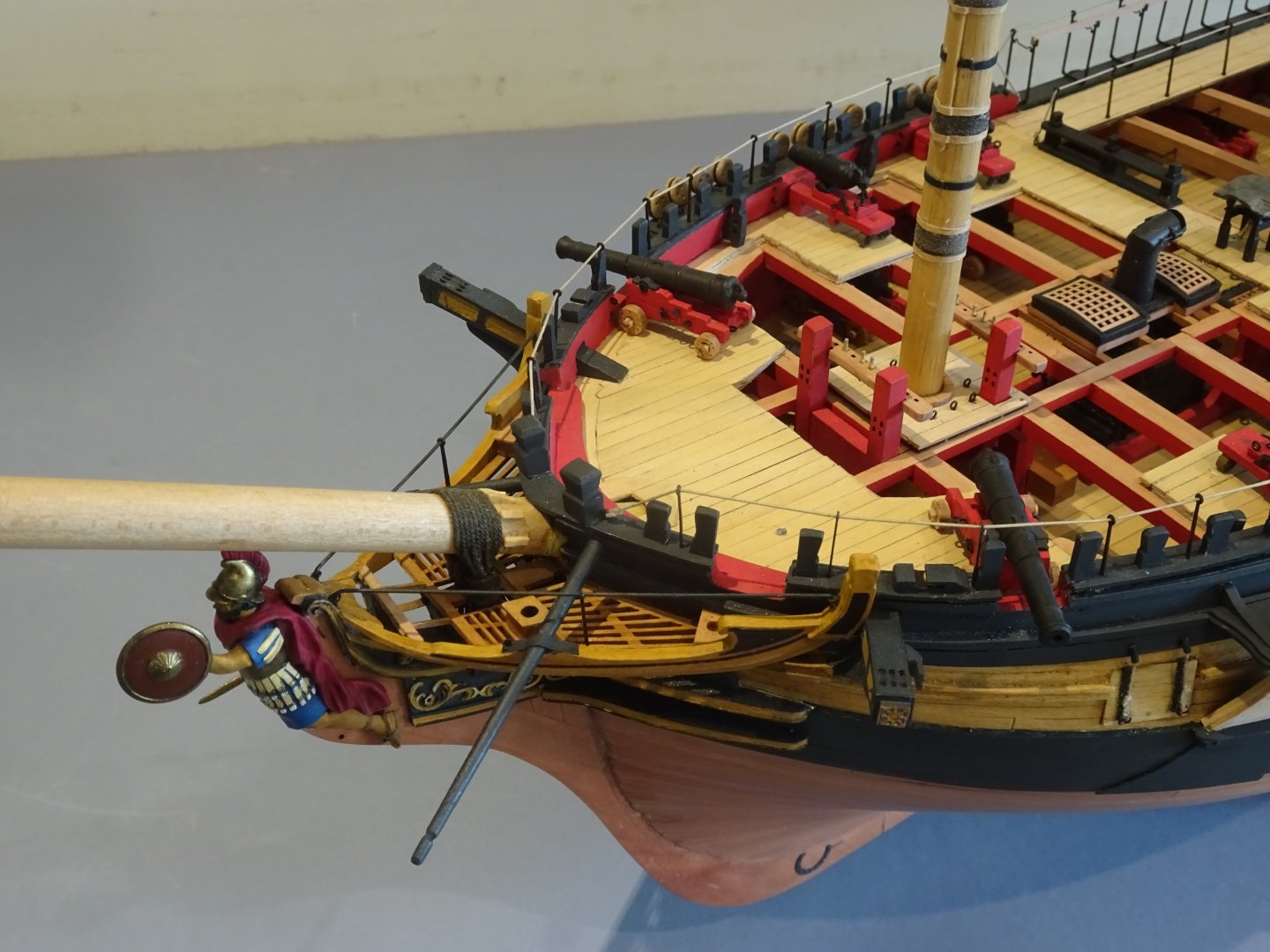
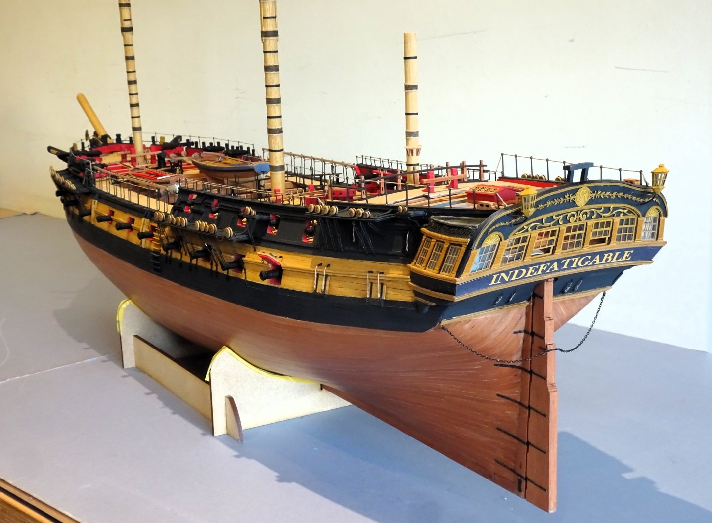
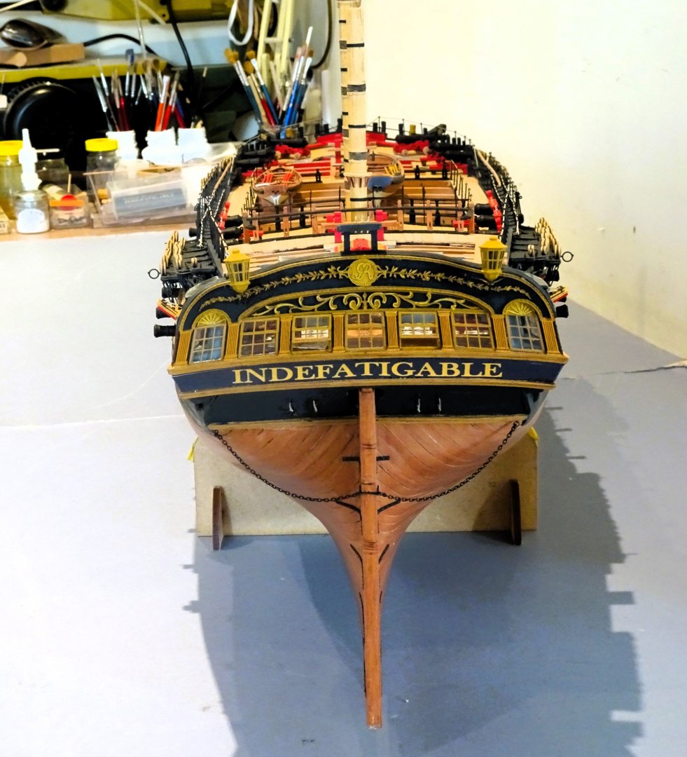
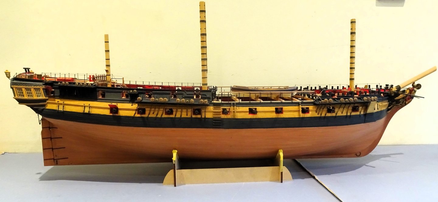
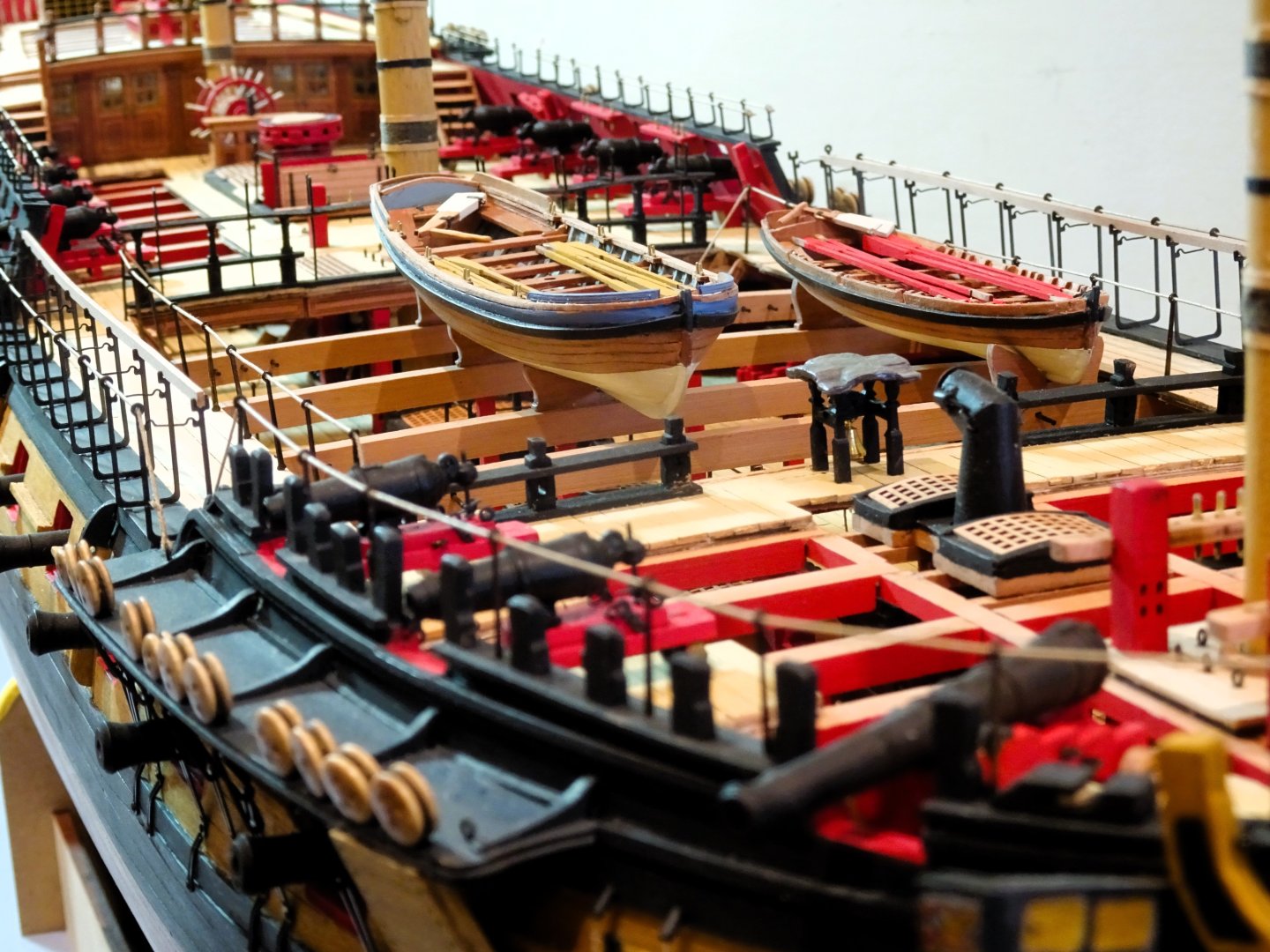
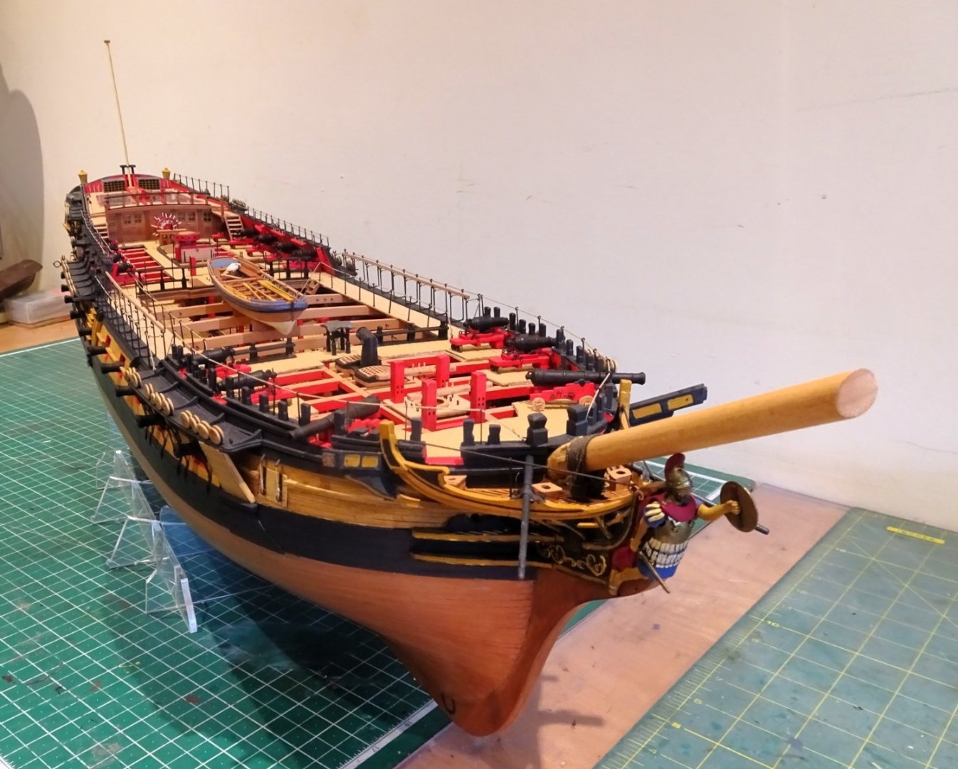
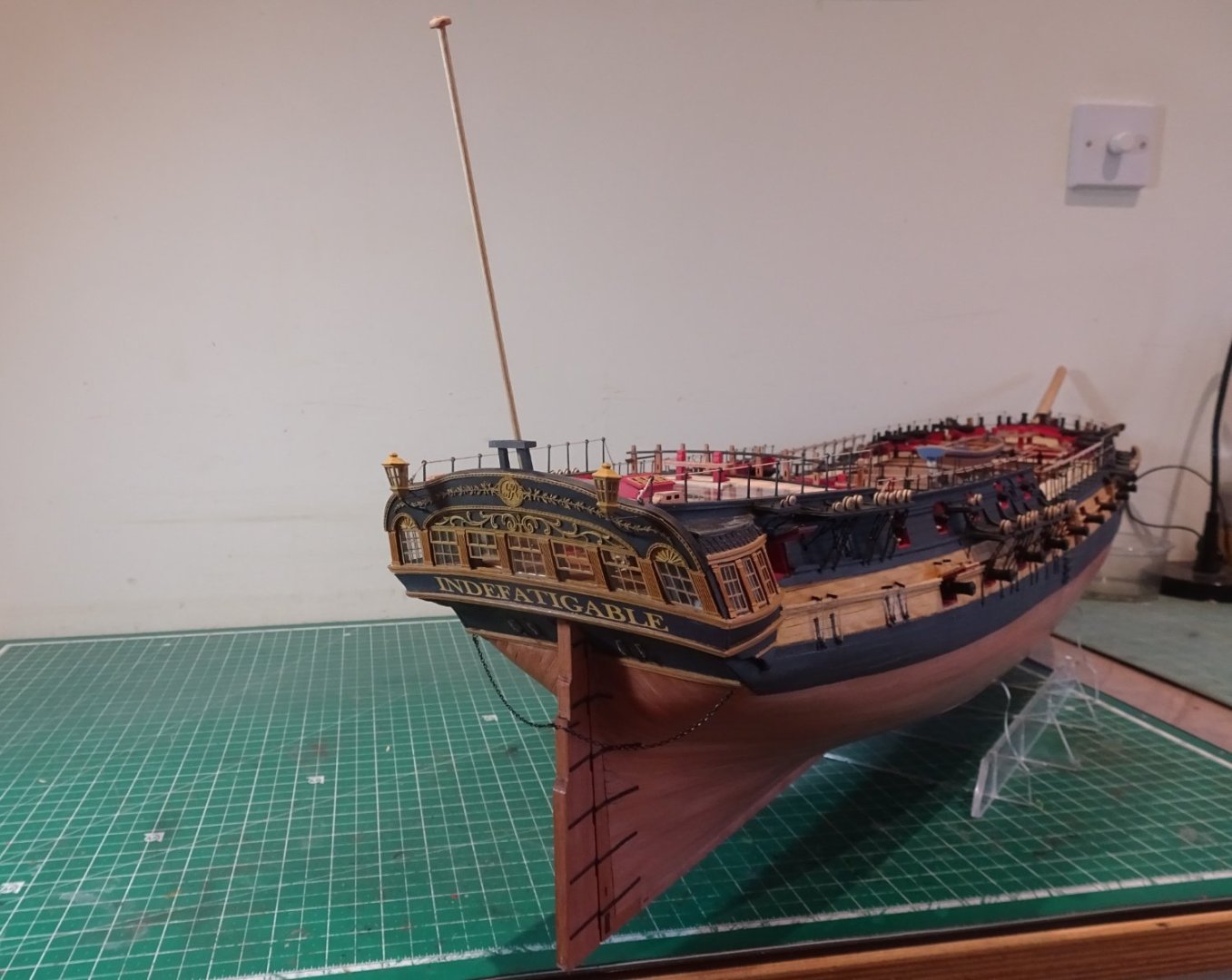
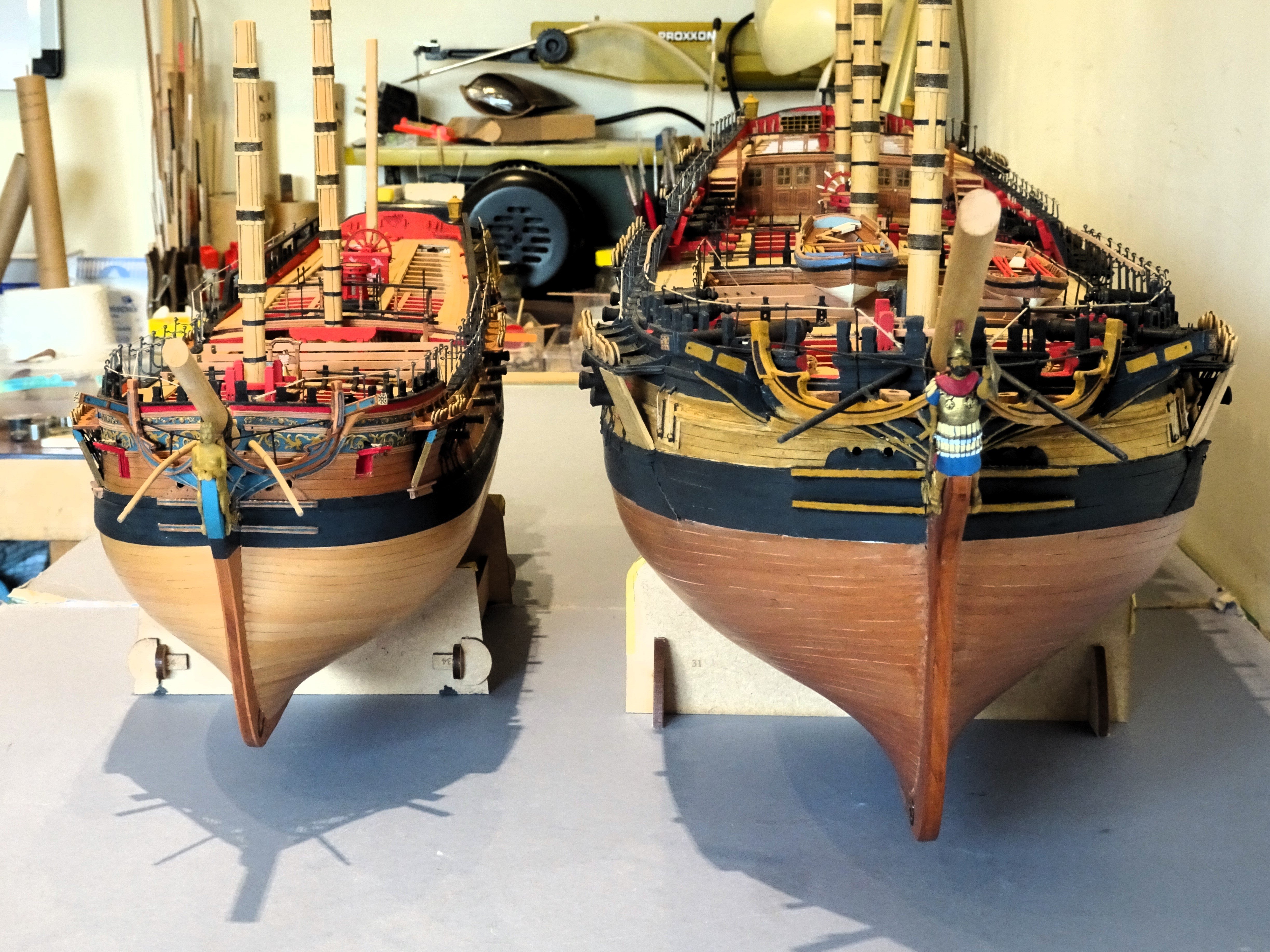
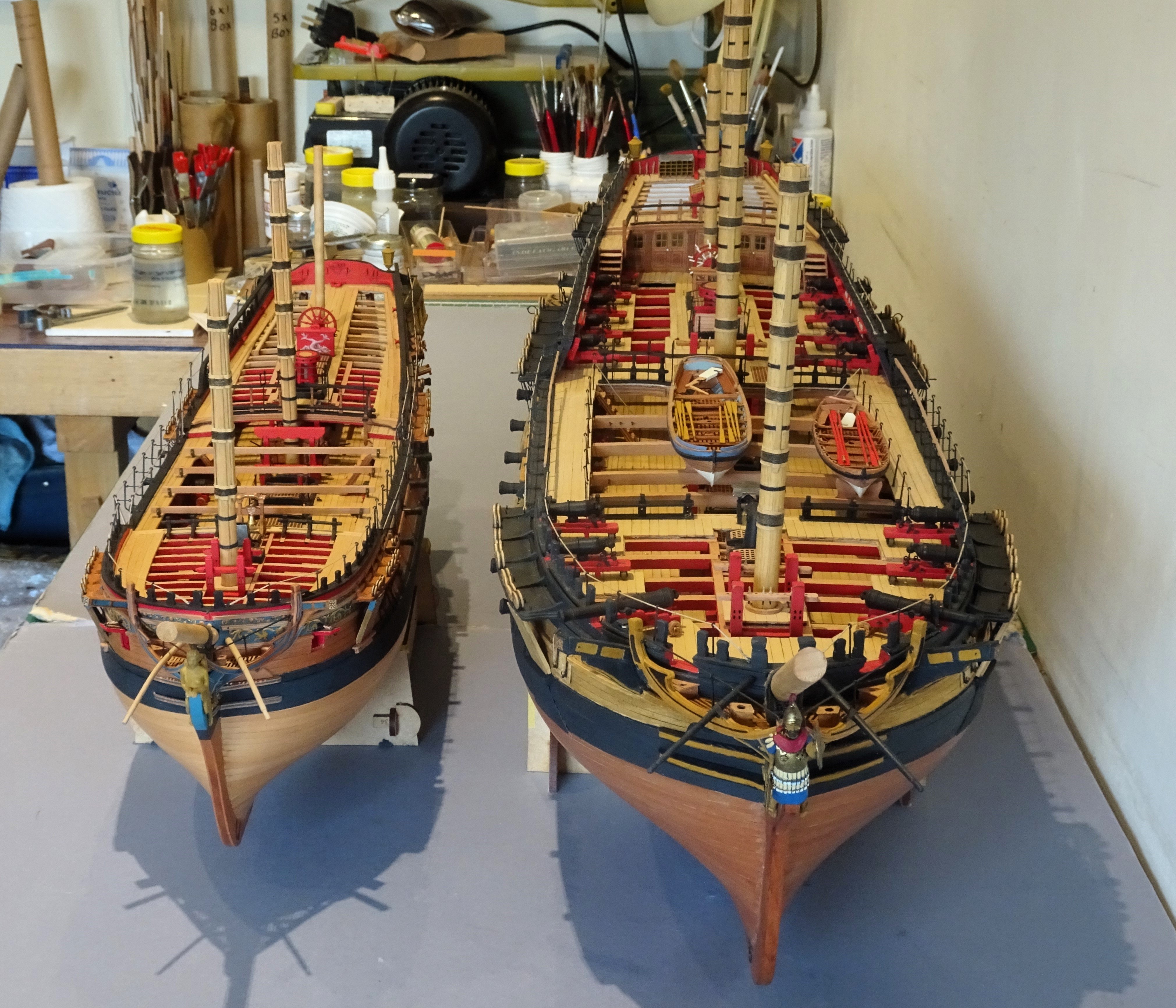
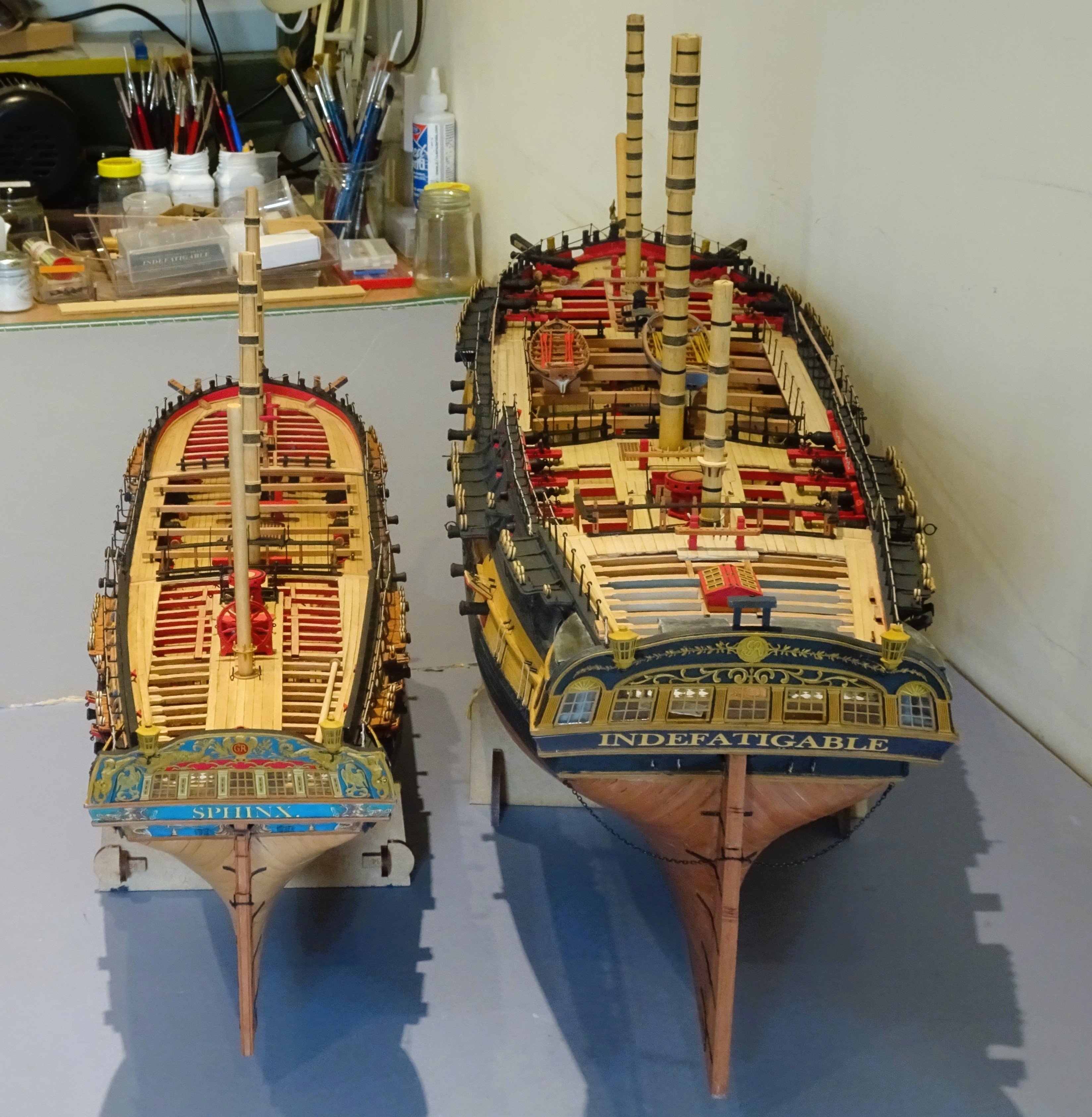
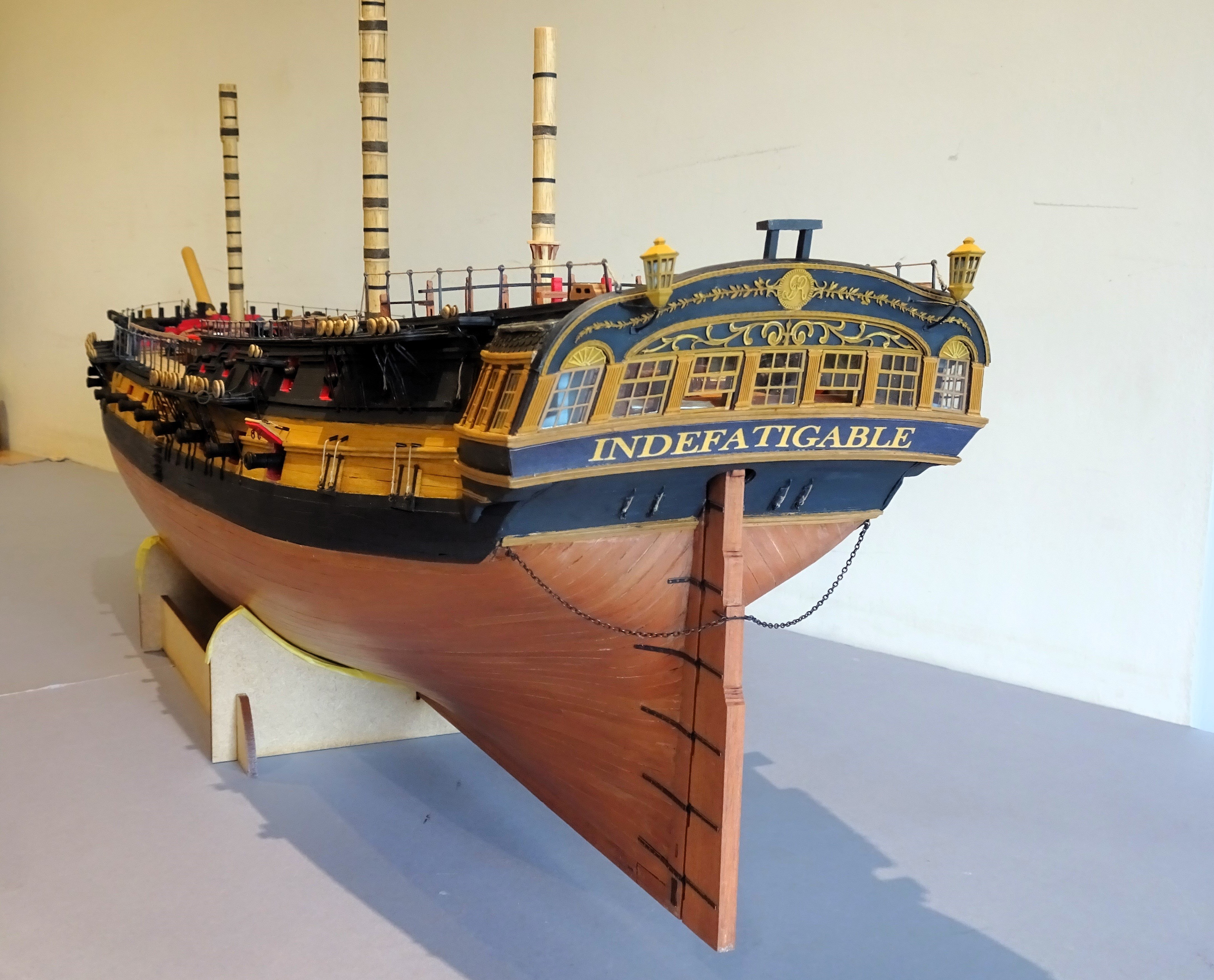
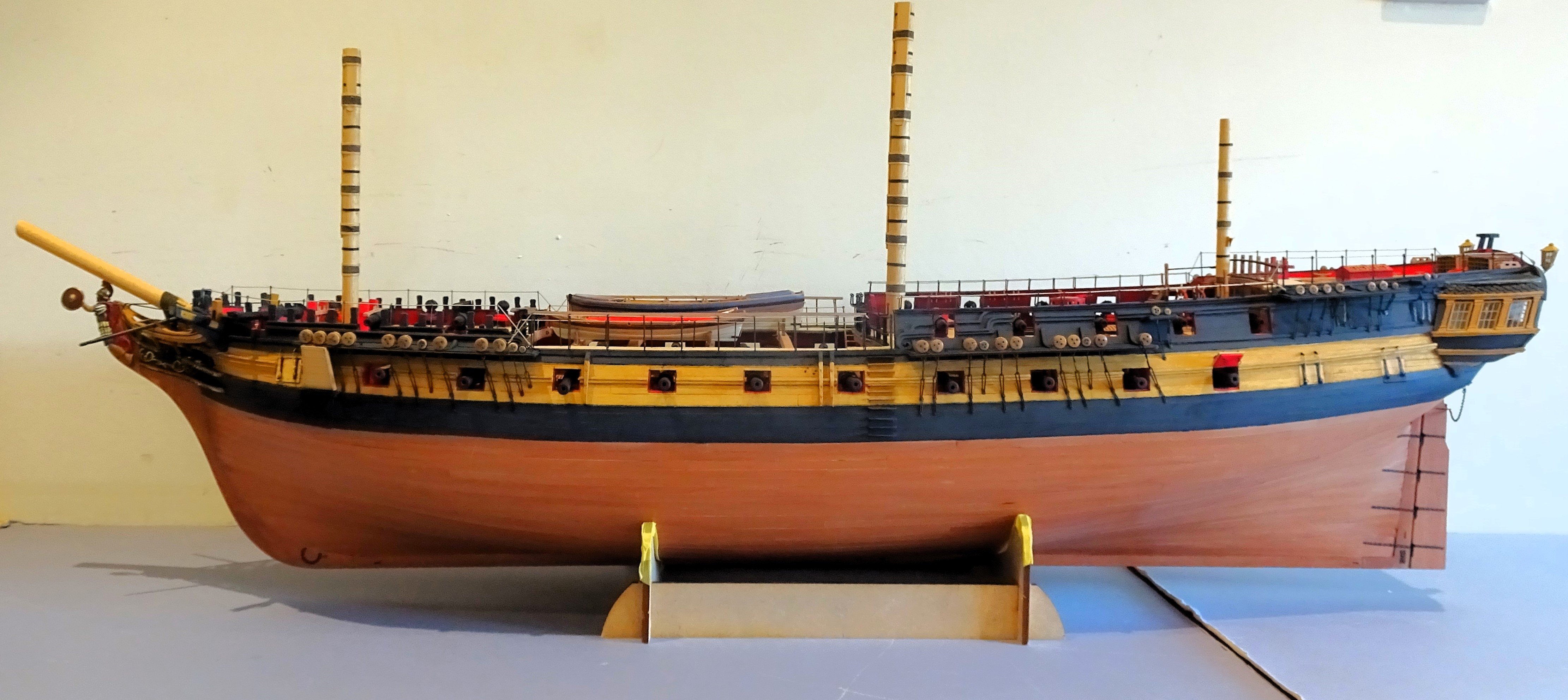
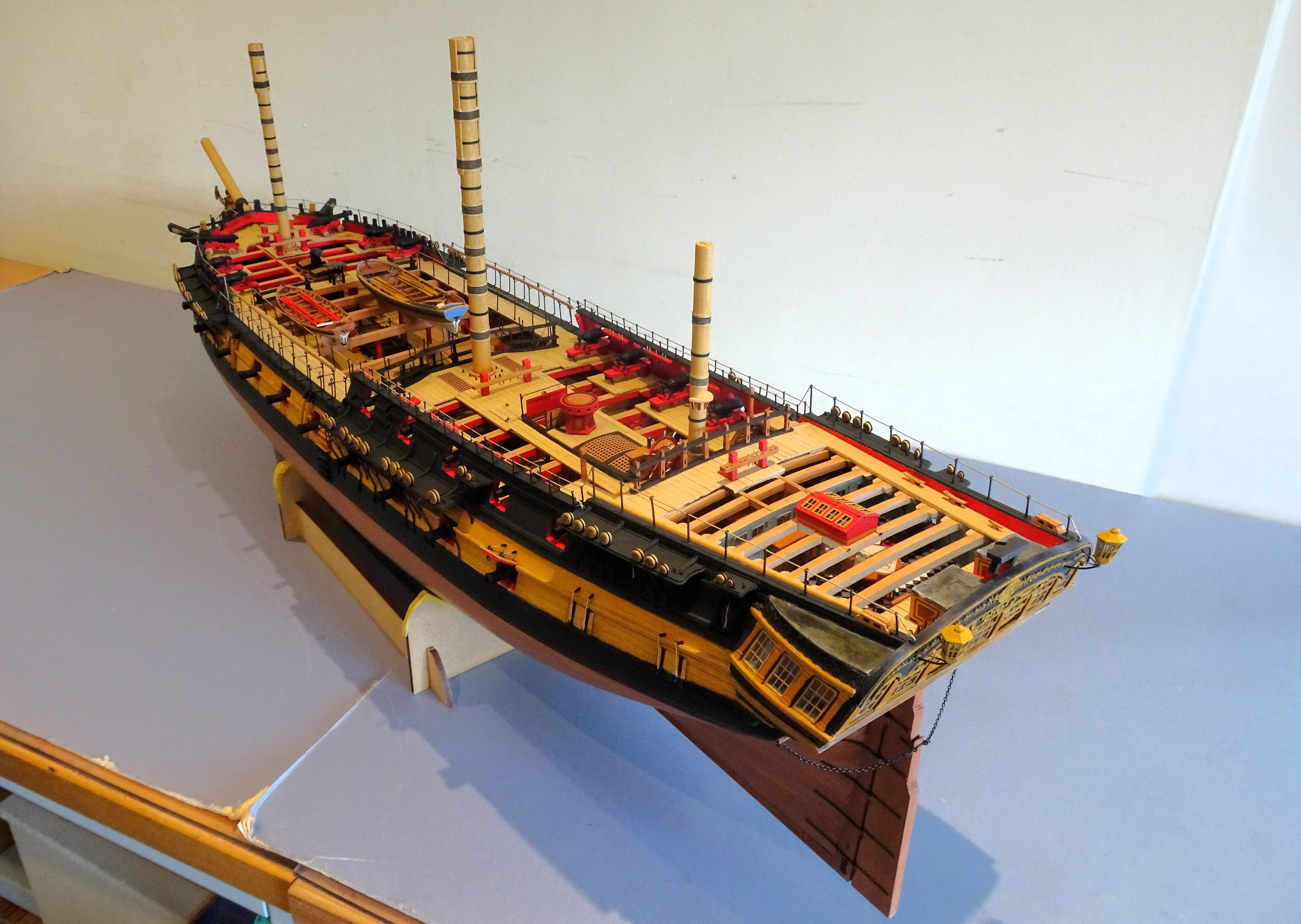
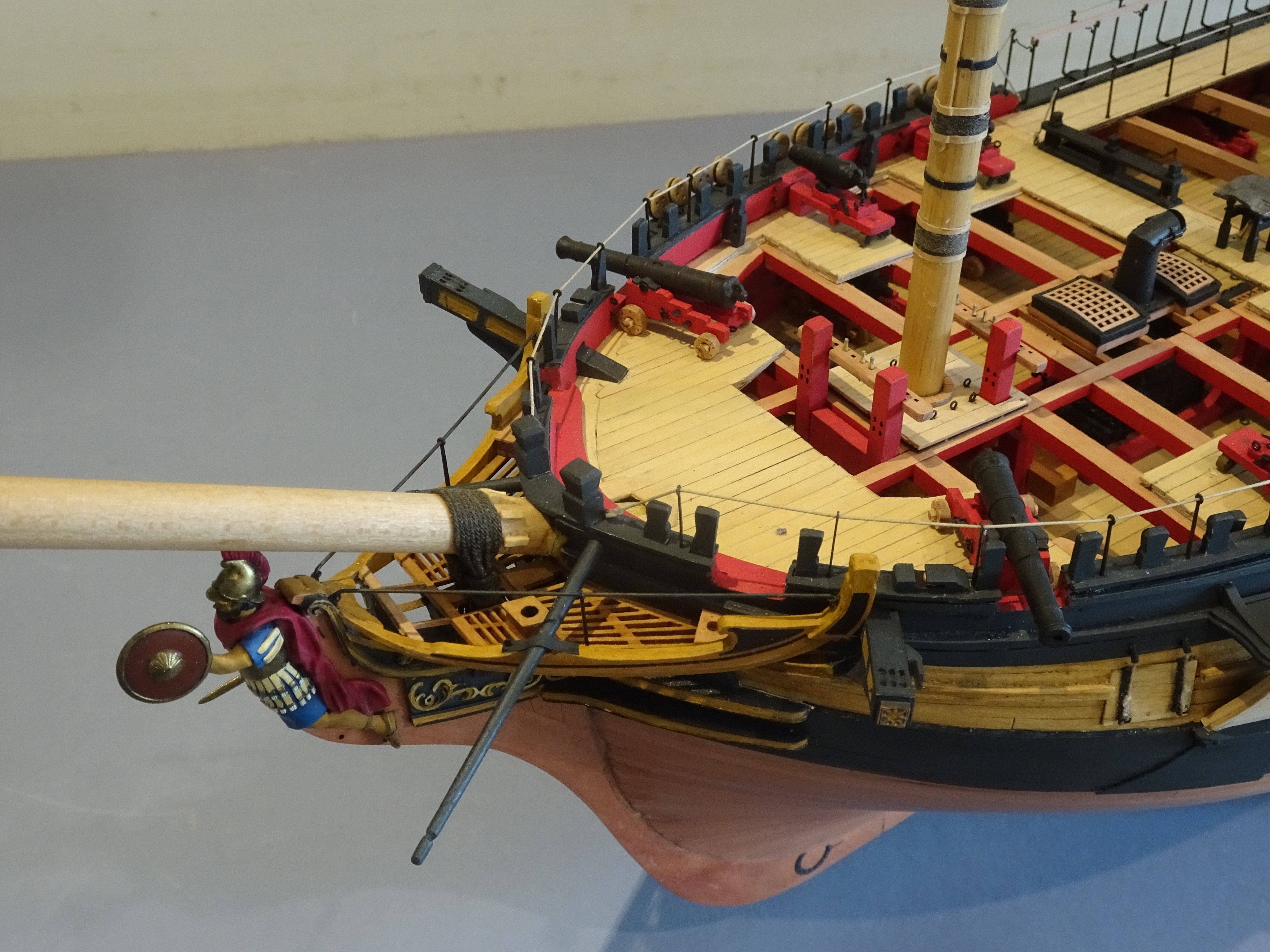
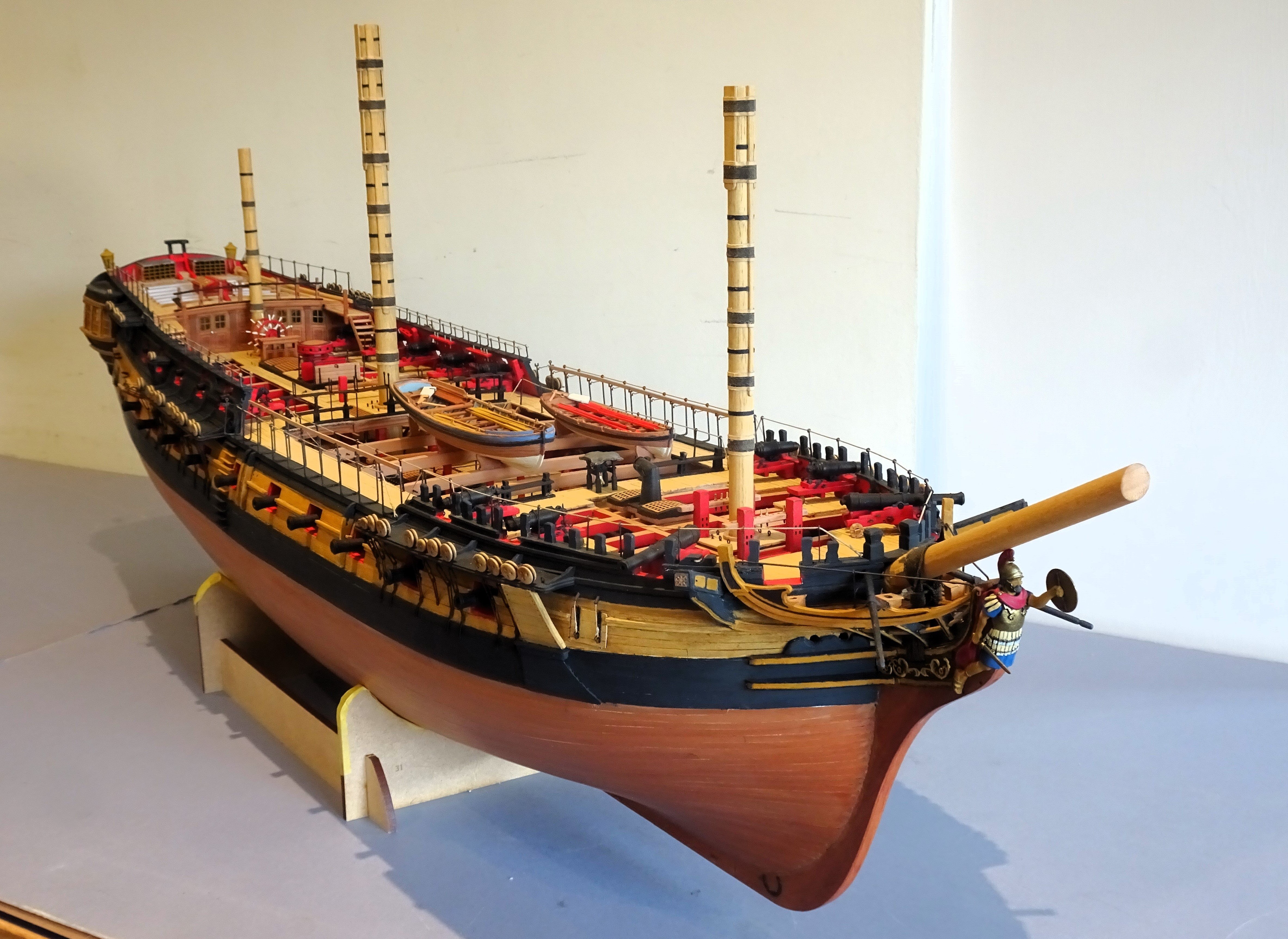
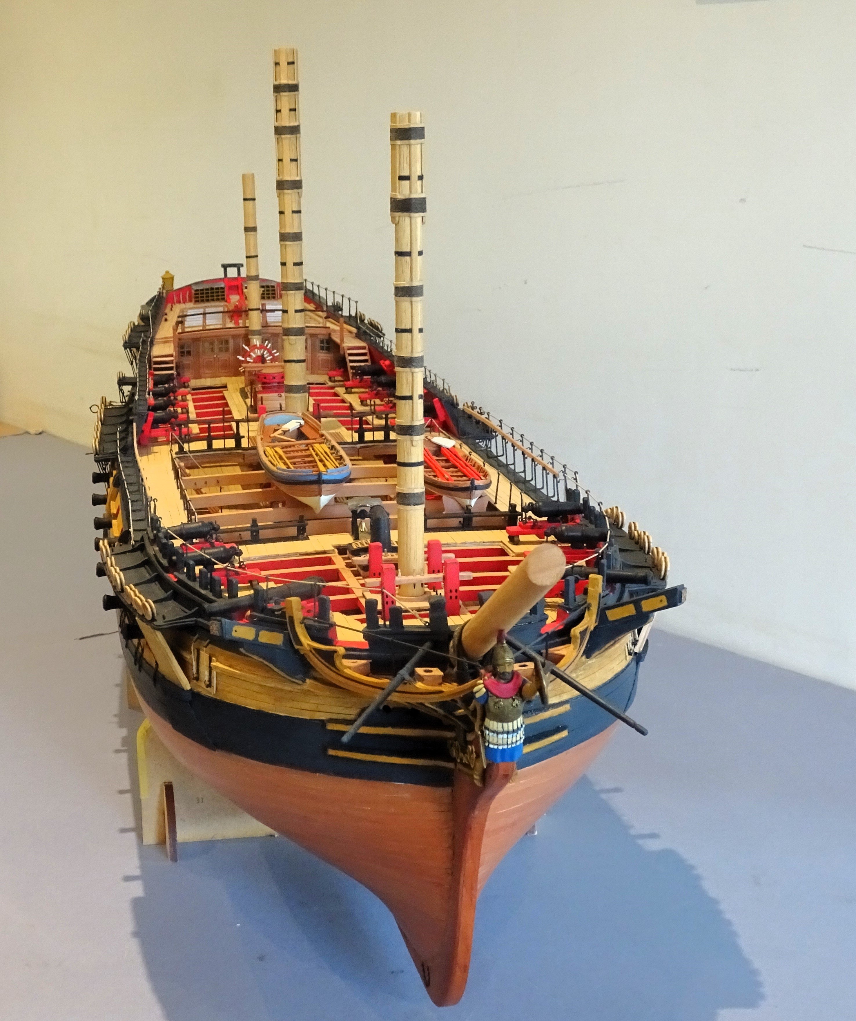
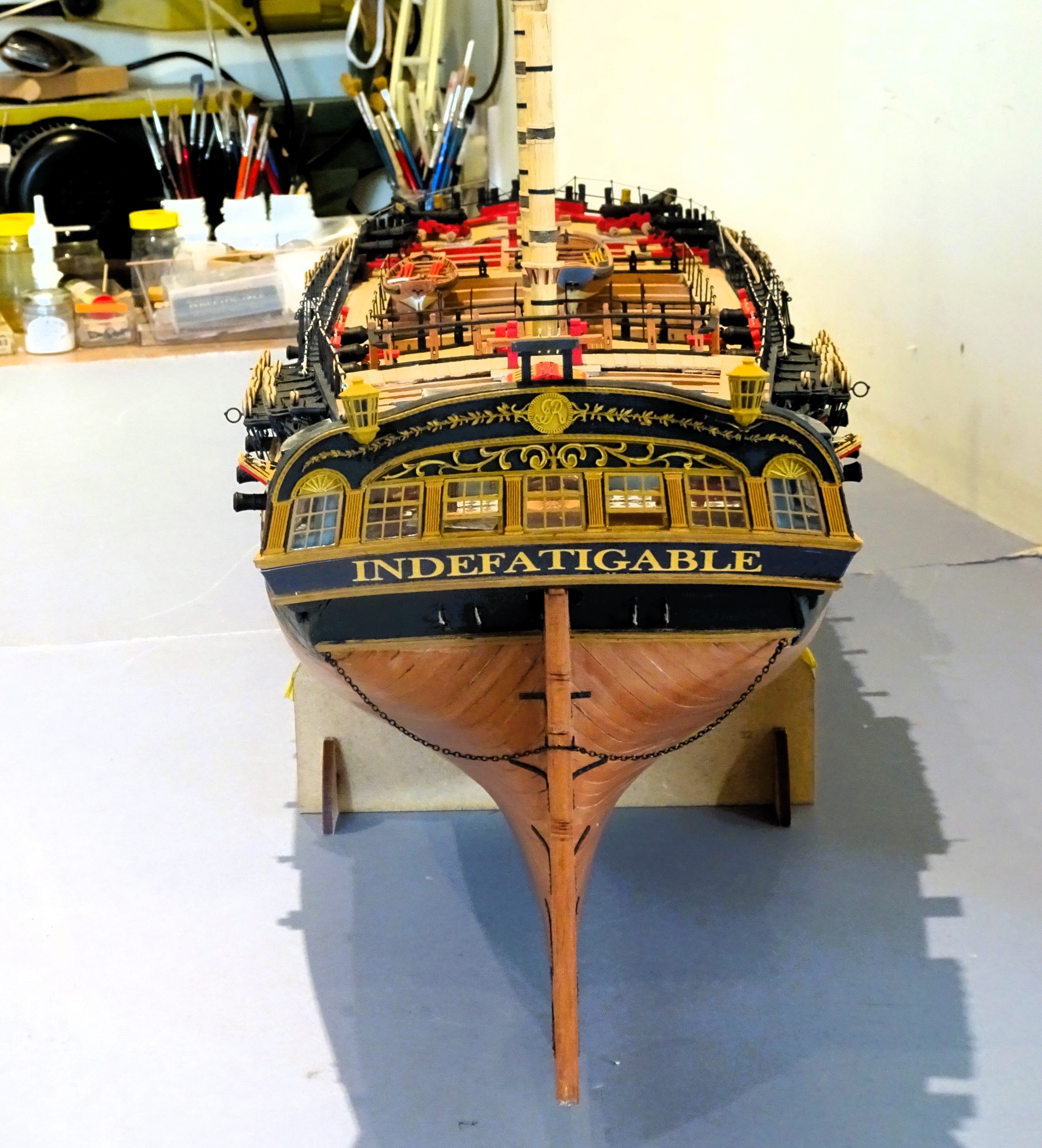
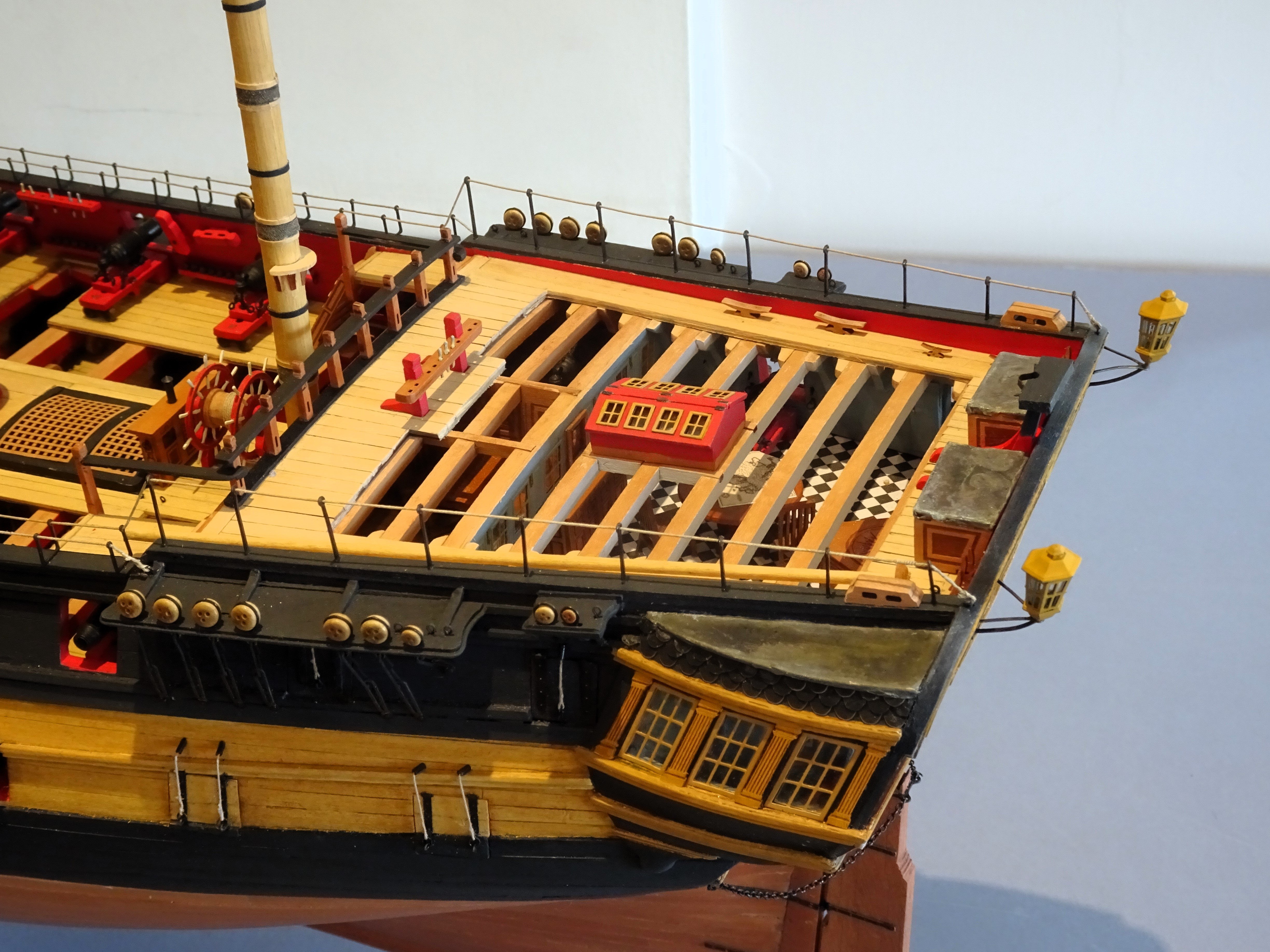
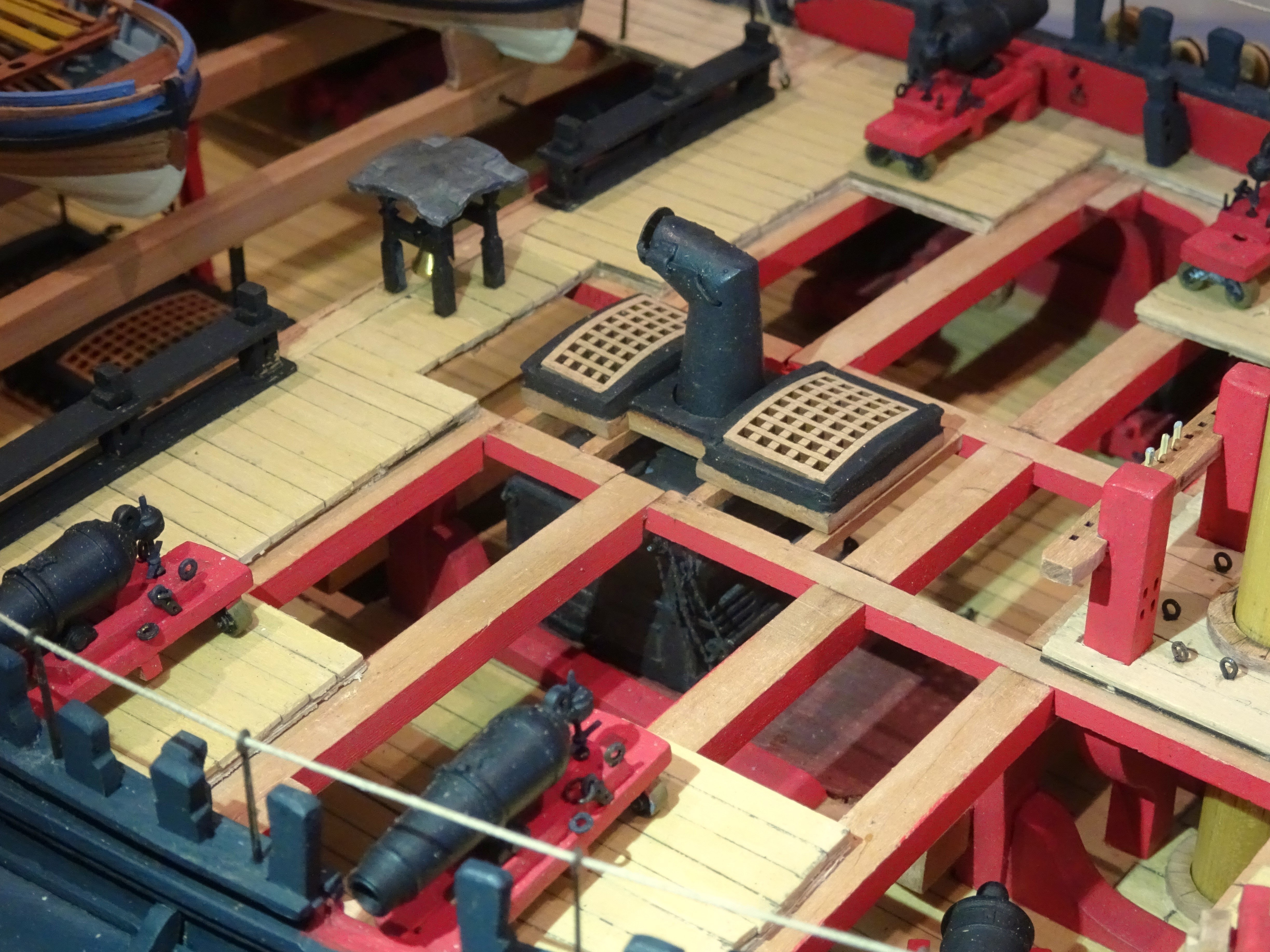
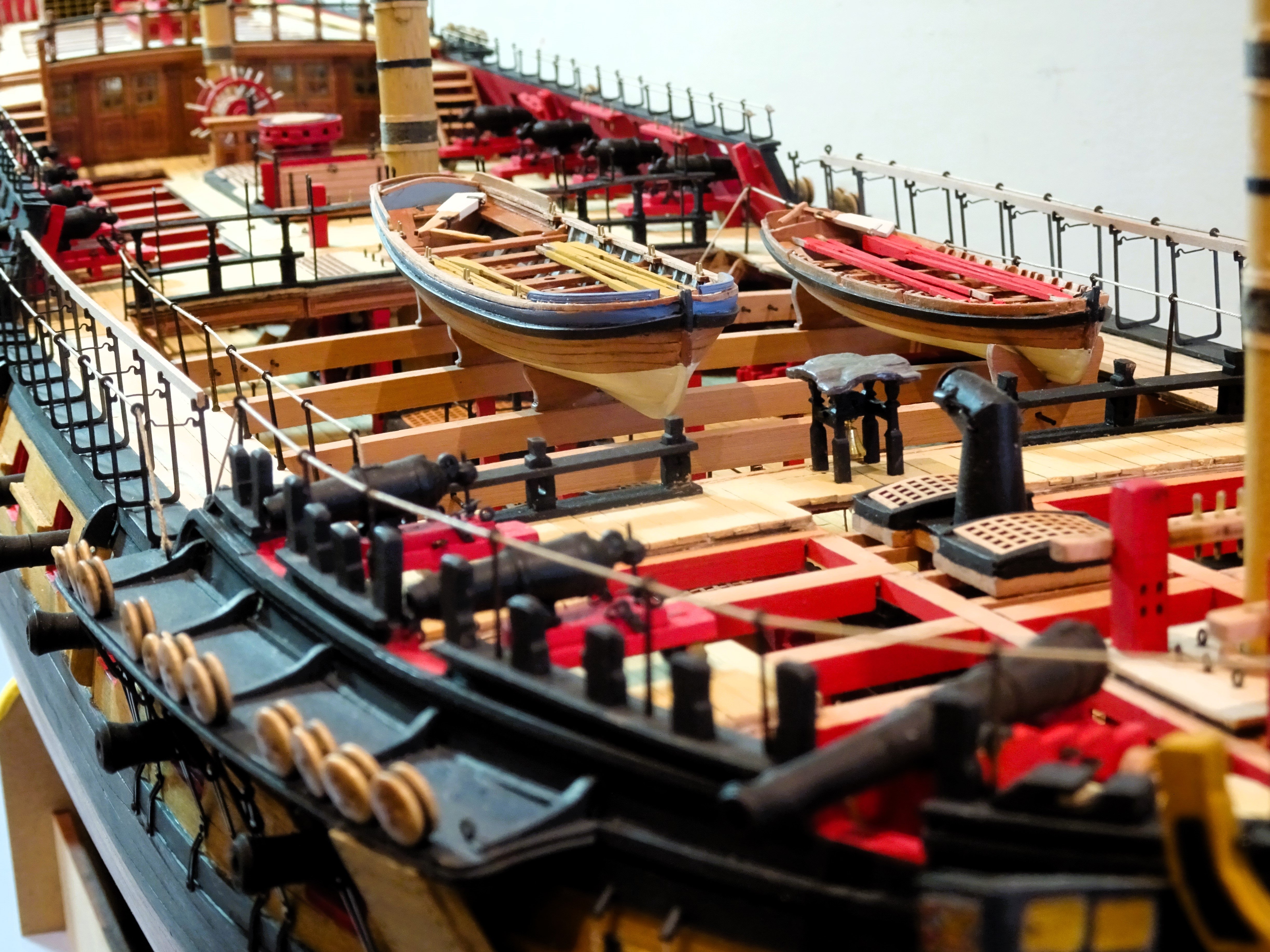
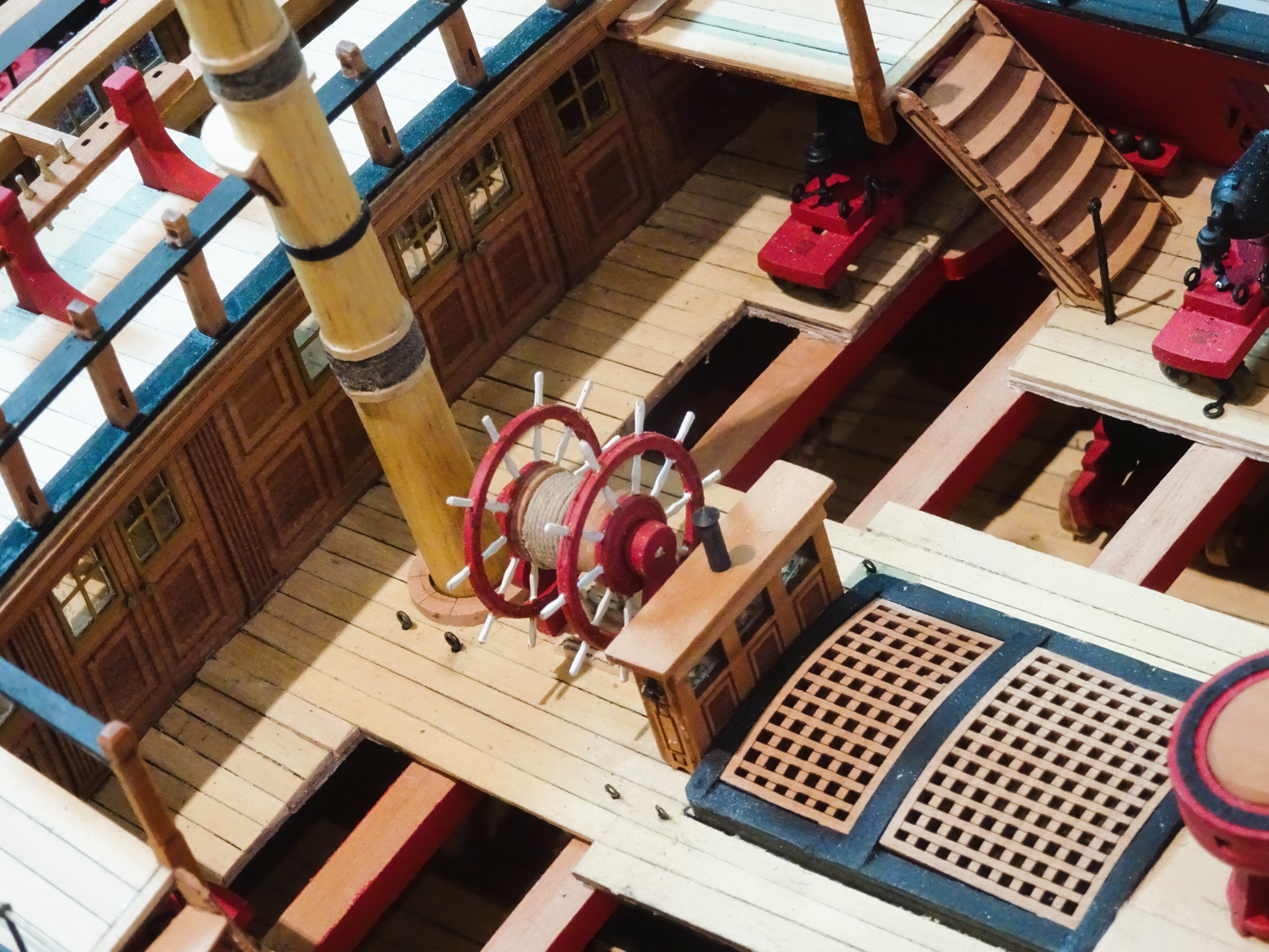
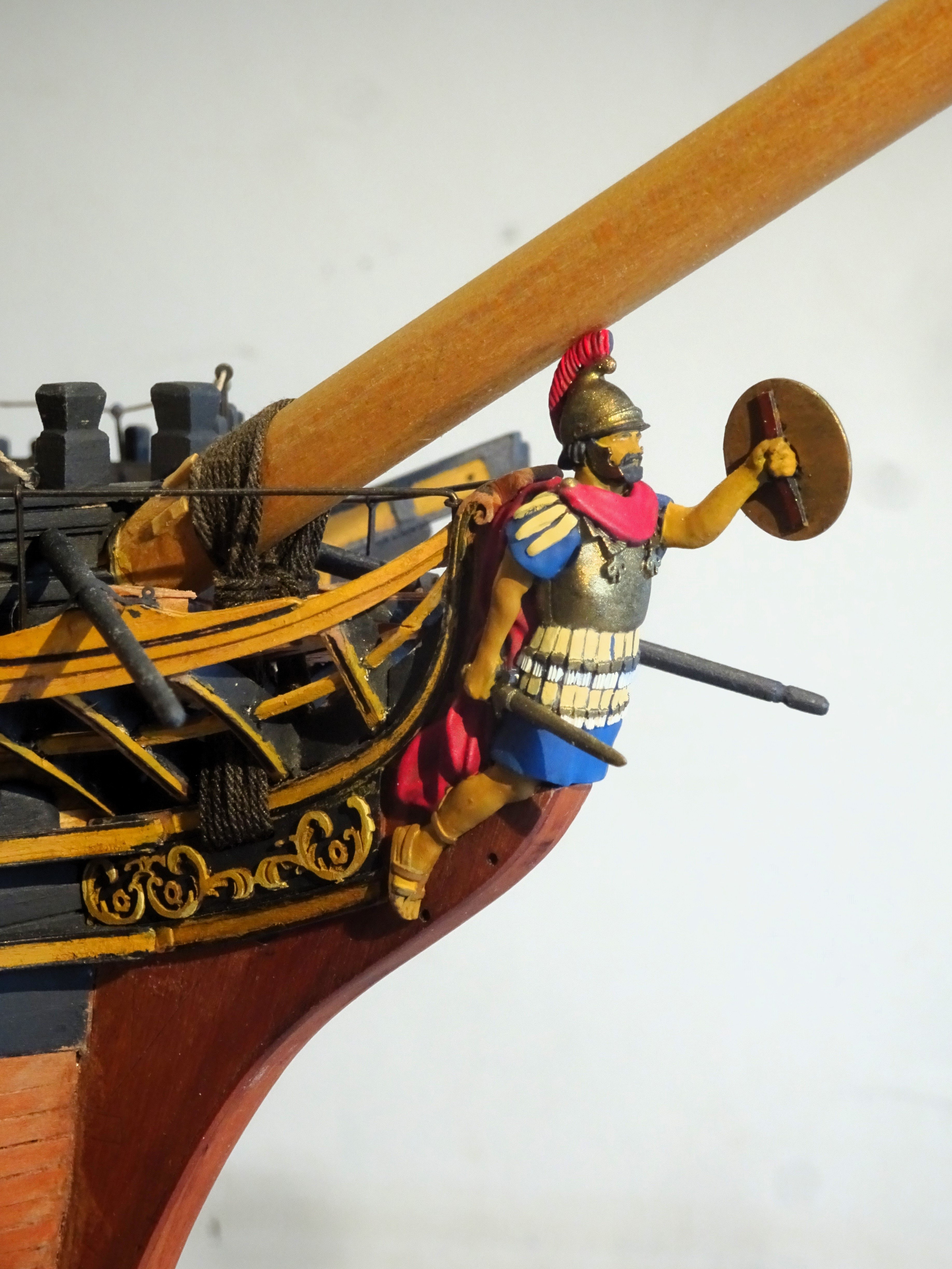
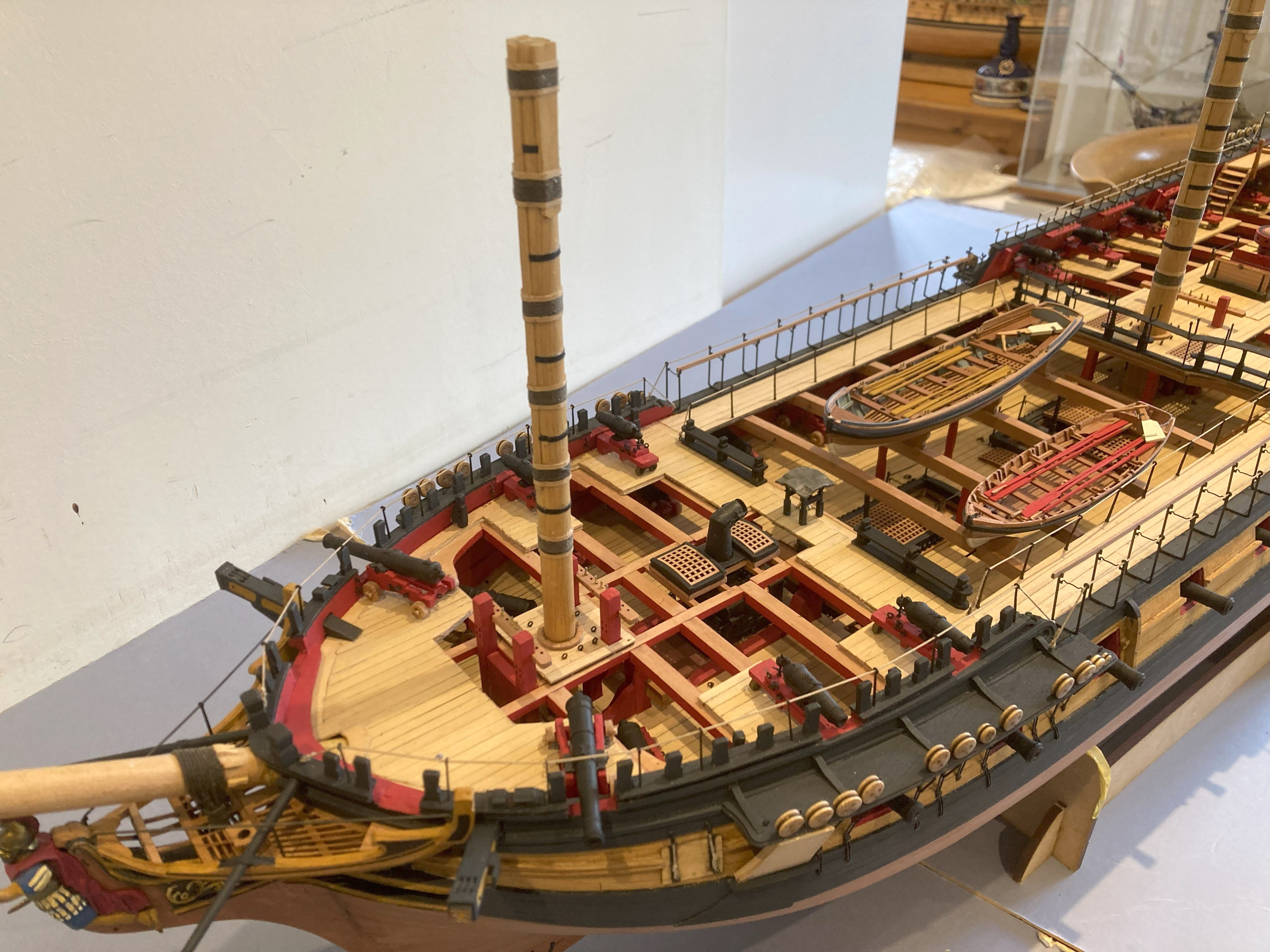
 Post One Hundred and Seventy-two Sphinx and ‘Indy’ I thought members may be interested to see the comparison between Chris’s two premier kits, Sphinx and Indefatigable. They sort of represent the alpha to omega of British frigates. Sphinx, the bijou 9 pounder vessel, and ‘Indy’, the pocket battleship of her day, carrying 24 pounders supplemented with 42 pounder carronades. I recall that when I built Sphinx I thought she was quite large, when ‘Indy’ arrived I thought I’m going to need a bigger bench! 04505 04506 04507 04508 04512 05413 05414 04517 If a large statement model is required ‘Indy’ is a good choice, but if masted and fully rigged she will take up a lot of room. Built Navy Board style she is still a heavy model and a glass case even with reduced height and width adds considerably to the weight. Sphinx is certainly of a size more amenable to a domestic setting; a pretty little frigate that appeals to my deeper affection for the more decorative vessels of the 18thc. before austerity took over as the expensive Napoleonic wars ground on. Indefatigable sort of spans this period, all black and yellow, no decorative topsides, but the stern gallery still looks good to my eye. She is modelled with an open Fo’csle before her bulwarks were built up, and she does have a magnificent Figure at her head. I am more than happy to have both in my collection. Thank you, Chris, for providing me with an engrossing thirteen months of work. It is a tribute to your designs, to be able to build a model of this quality and detail in such a short time. Thanks are also due to James, for producing the prototype ‘Indy’ build which provided a very useful reference guide. B.E. 02/05/2024
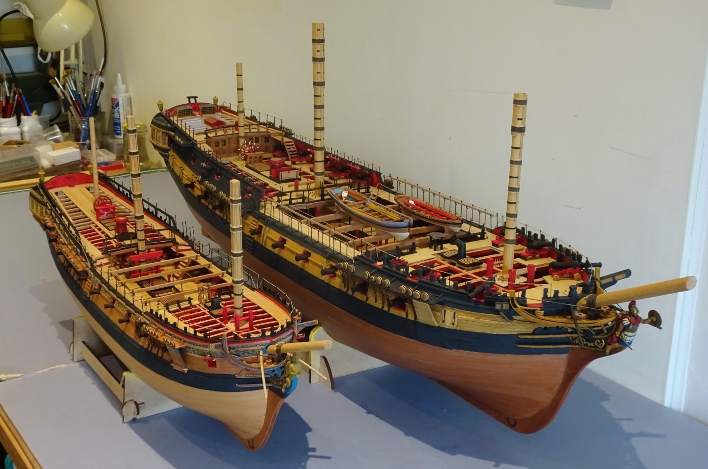


- 648 replies
-
- 32
-

-

-

-
- Indefatigable
- Vanguard Models
- (and 1 more)
-
Thank you guys for your supportive comments and likes throughout this build, hope it will be useful to those following on. @ Nils – I have a glass case ready; it was cheaper than using acrylic, but the downside is weight. It is going to be an interesting exercise getting her into display position.🤔 B.E.
- 648 replies
-
- 4
-
-
- Indefatigable
- Vanguard Models
- (and 1 more)
-
Post One hundred and Seventy-one Album photo's I have at last got around to taking the completion photo’s which will form part of the Photo build record book that I’m currently putting together. 4395 4361A 4392 4364 4365 4391 4390 4396 4369 4405 4395 2161A 2145a 4397 2162a 2164a 4380 4379 4388 4494a I am currently faffing around with a clinker built 18’ cutter, and ‘Indy’ is yet to be enclosed in her case, so the story has not quite ended. Then there’s the 26’ Launch, still on my mind. Cheers, B.E.


- 648 replies
-
- 51
-
-
-
- Indefatigable
- Vanguard Models
- (and 1 more)
-
Hi Bug, I used three each side on the Fore and Main Topmast shrouds, none on the Mizen. I used the aftermost ones for the fore and Main T’gallant yard lifts. I didn’t use the other two. Two each on the Fore and Main lower Shrouds, one on the aftermost Mizen shroud (used for the Mizen Topmast yard Lift) I recall that I used the TFFM Vol IV to decide which lines went where. TFFM indicates the fore and Main topmast shroud cleats were also used for the t’gallant clues, and the Fore topmast shroud cleats for the Main T’gallant Bowlines. I belayed a lot of lines to the rails as indicated in the TFFM. There are no belaying pins on my Pegasus. Nice work on those shroud cleats.👍 B.E.
- 419 replies
-
- 3
-
-
- Victory Models
- Pegasus
- (and 2 more)
-
Thanks Mike, Vol 111 arrived this morning, quick delivery across the pond. Quite a hefty tome, I look forward to savouring its contents in the coming days. Regards, B.E.
-
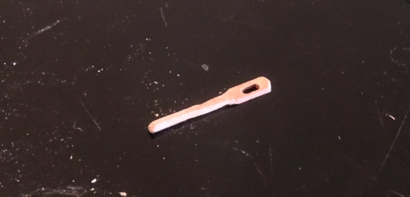
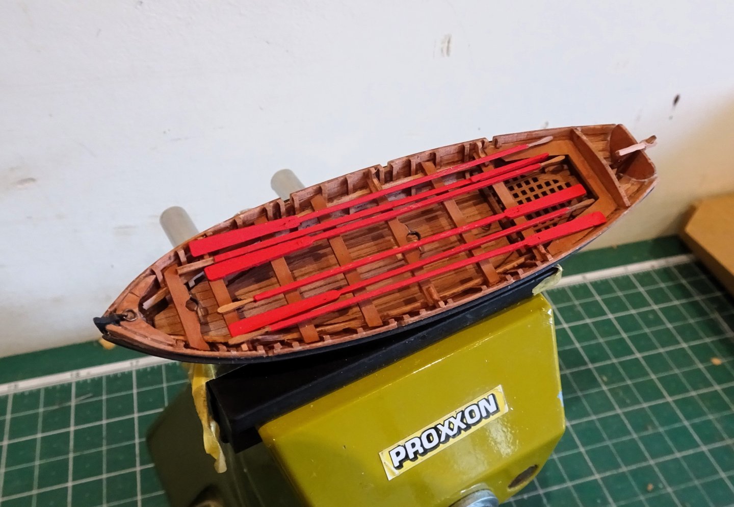
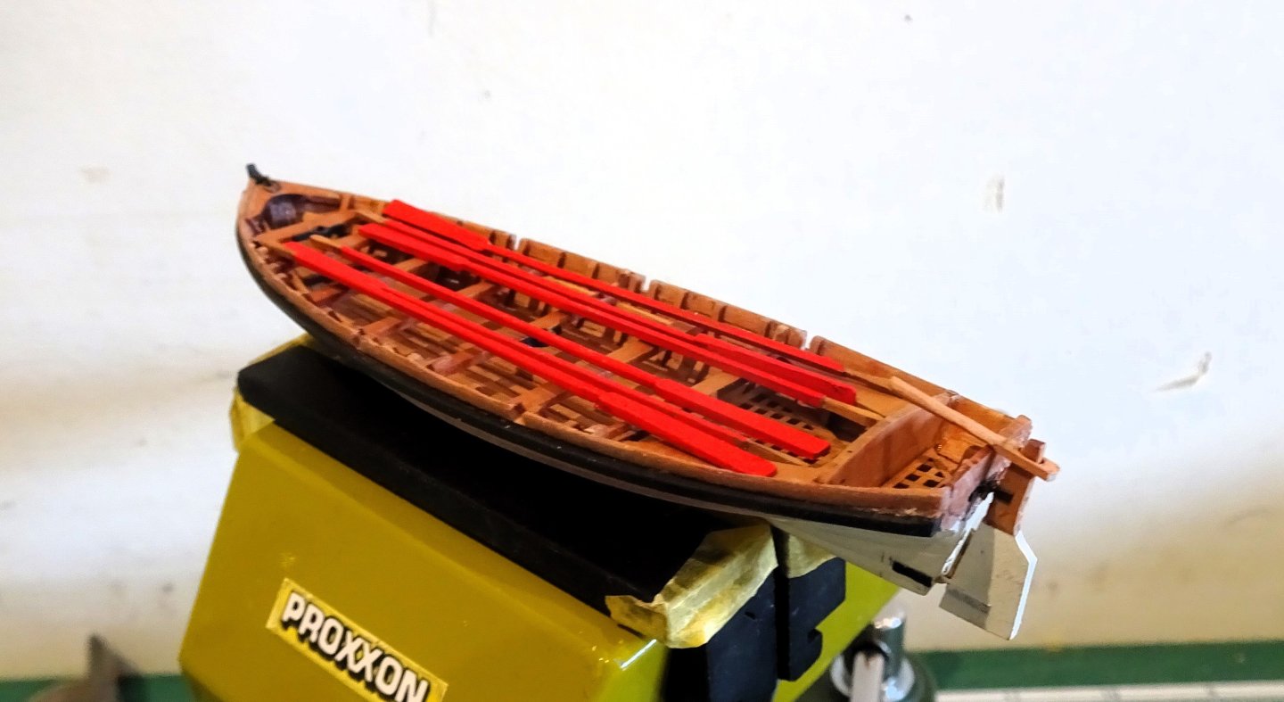
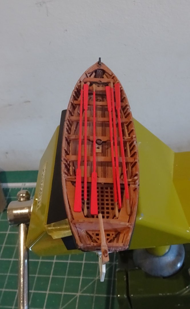
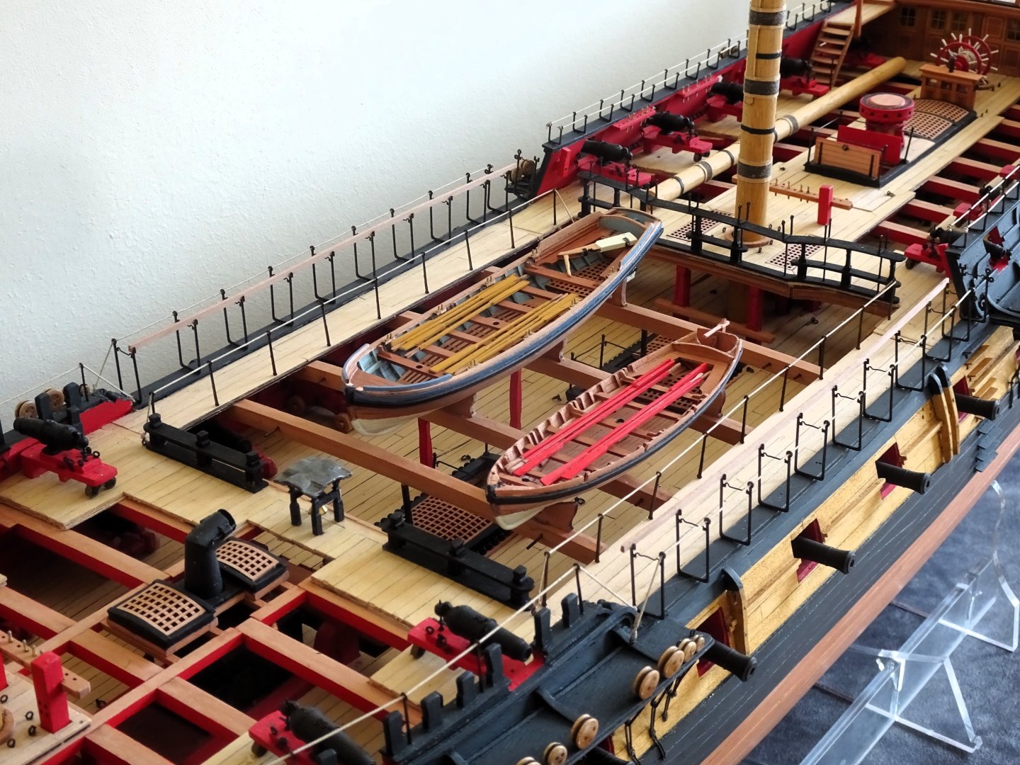
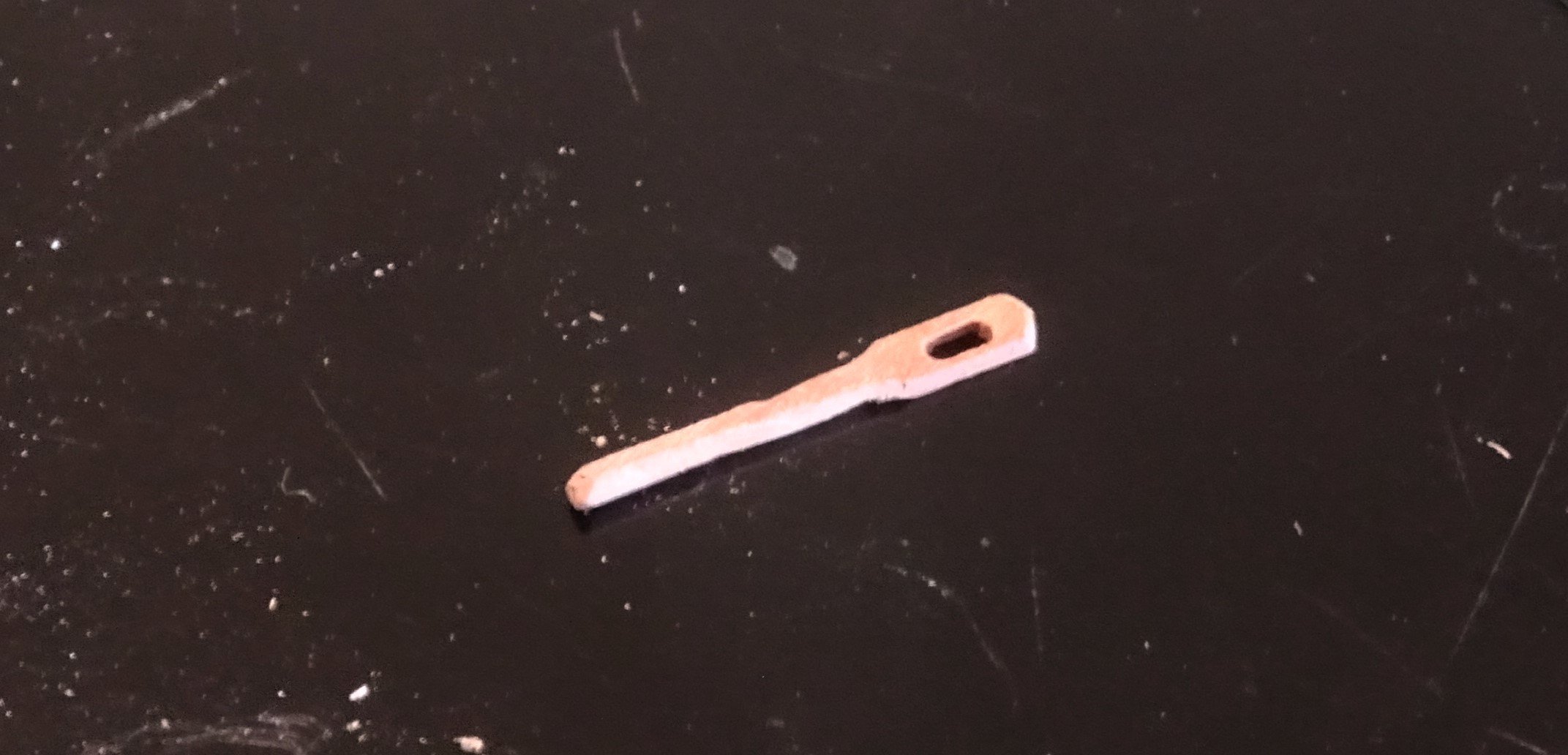
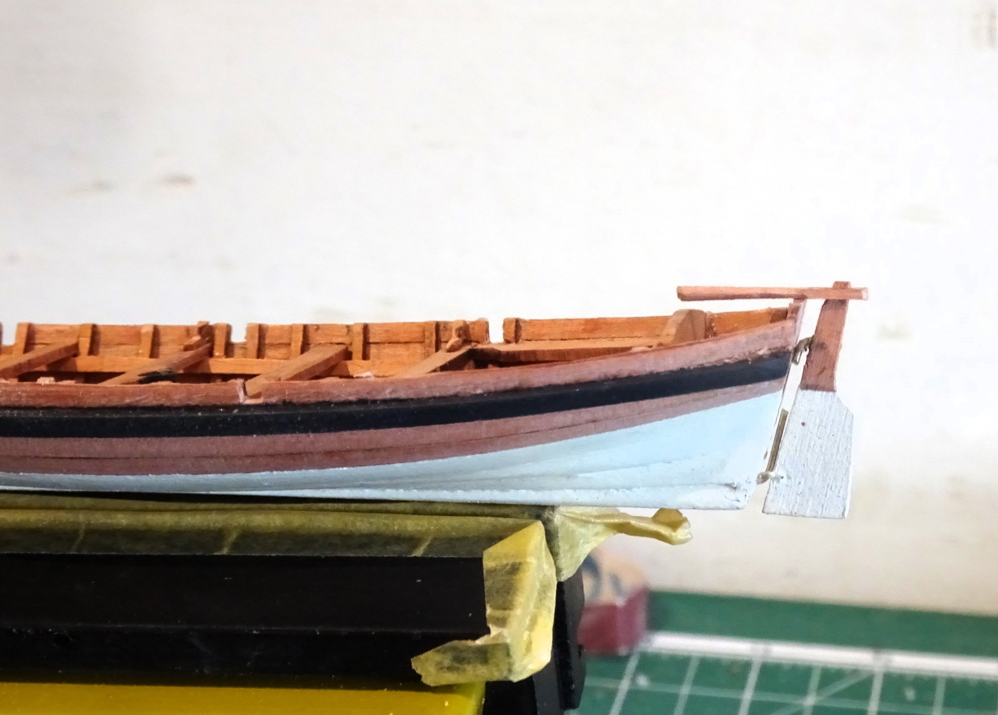
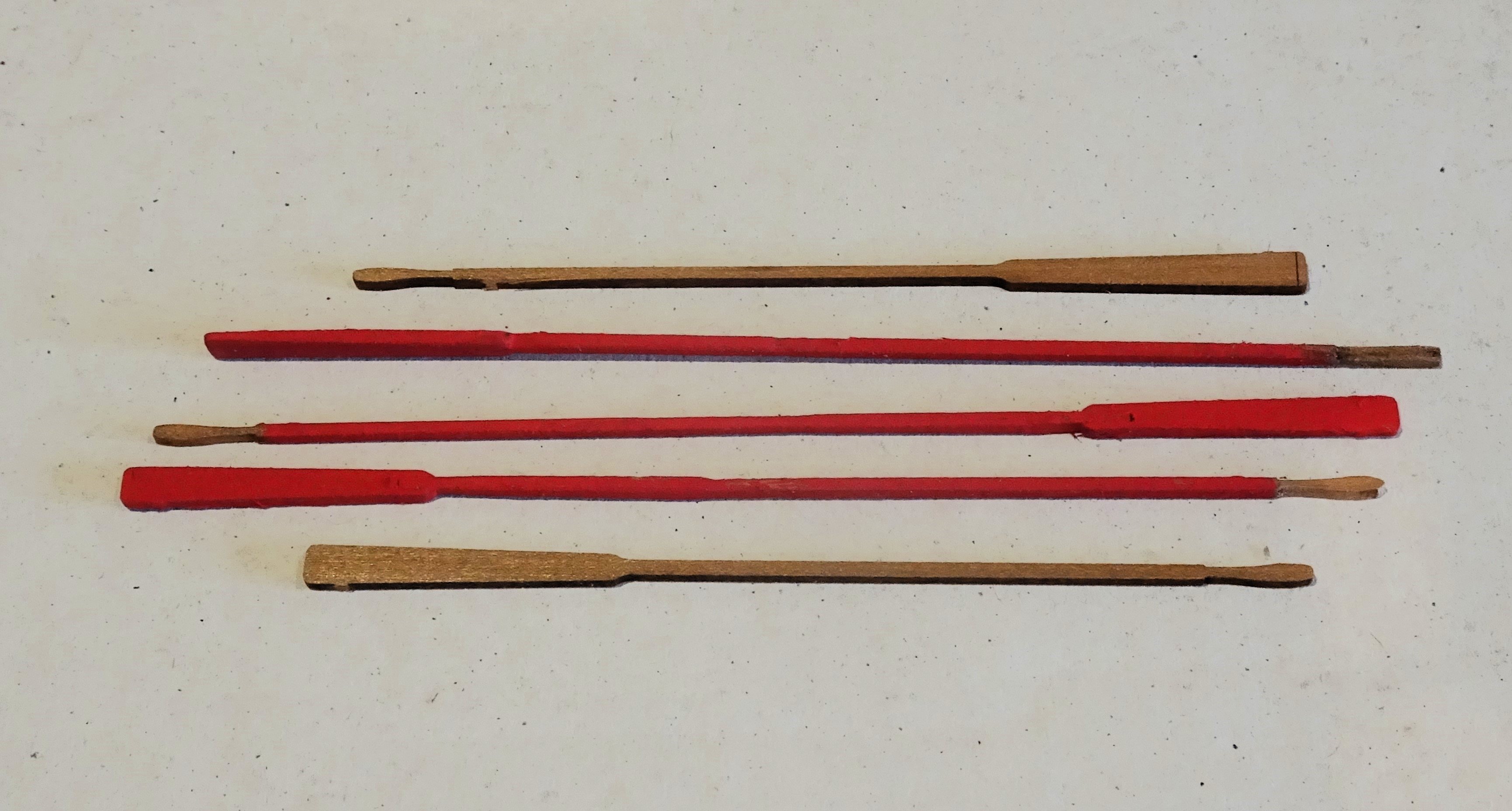
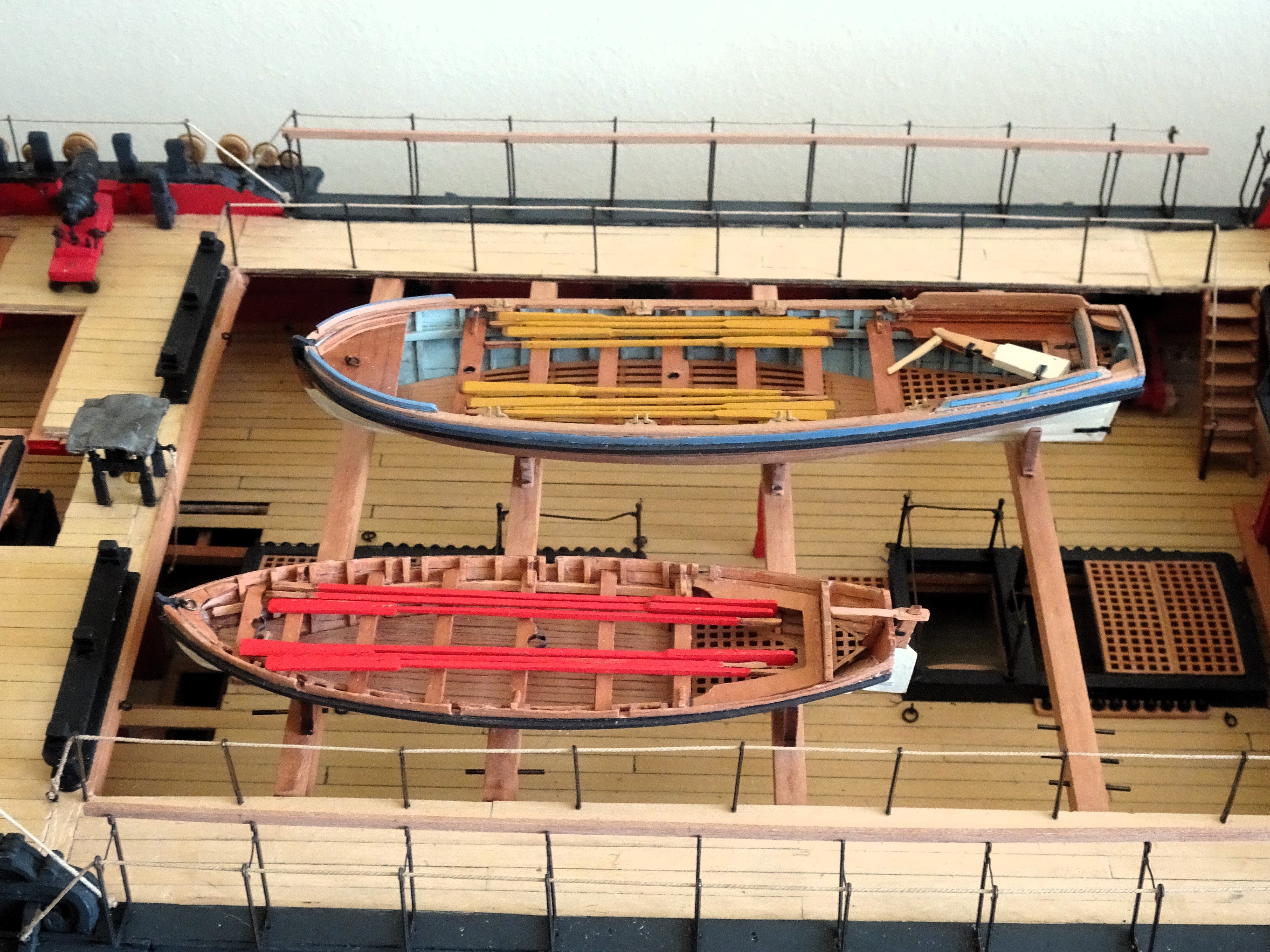
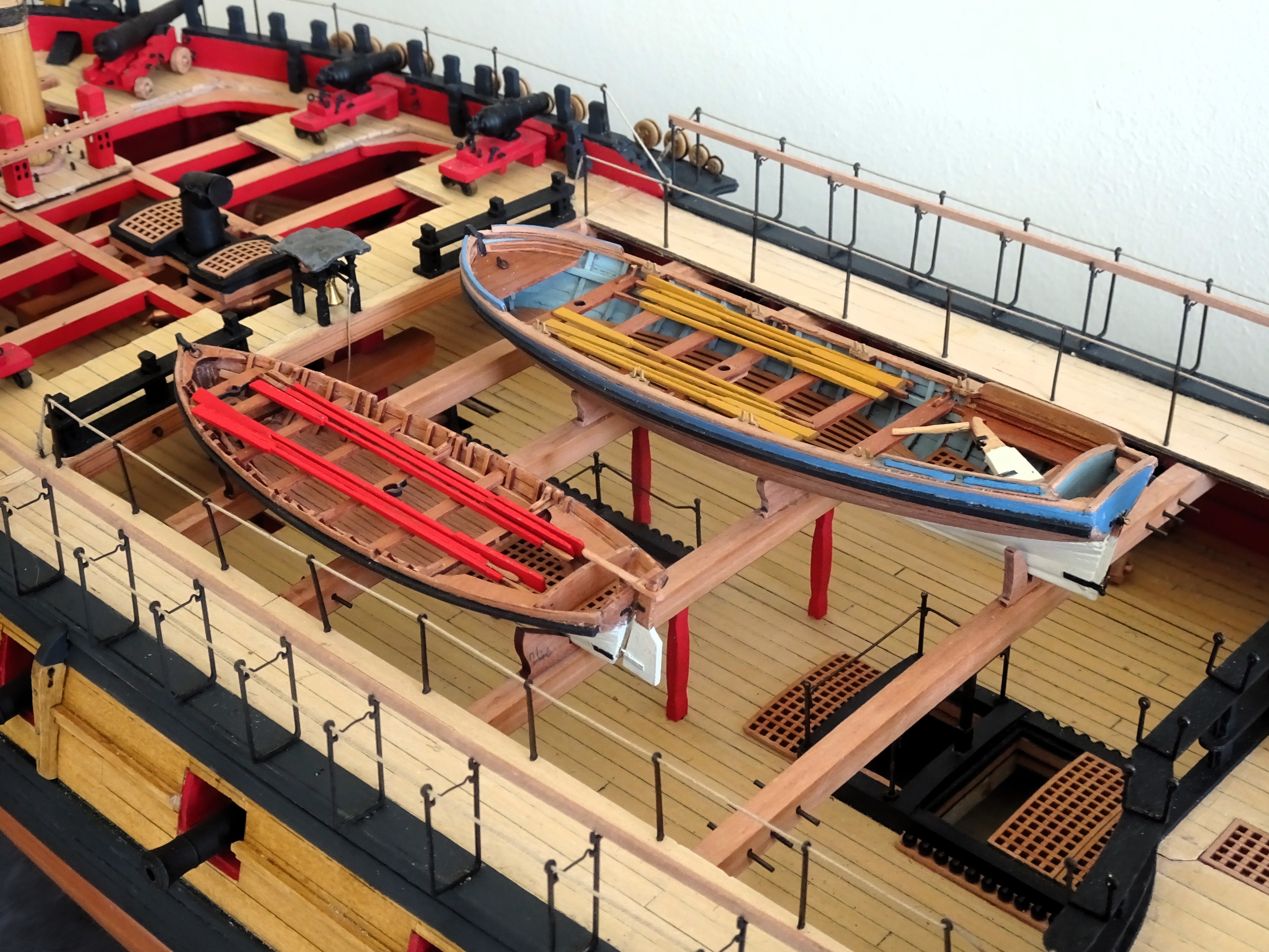
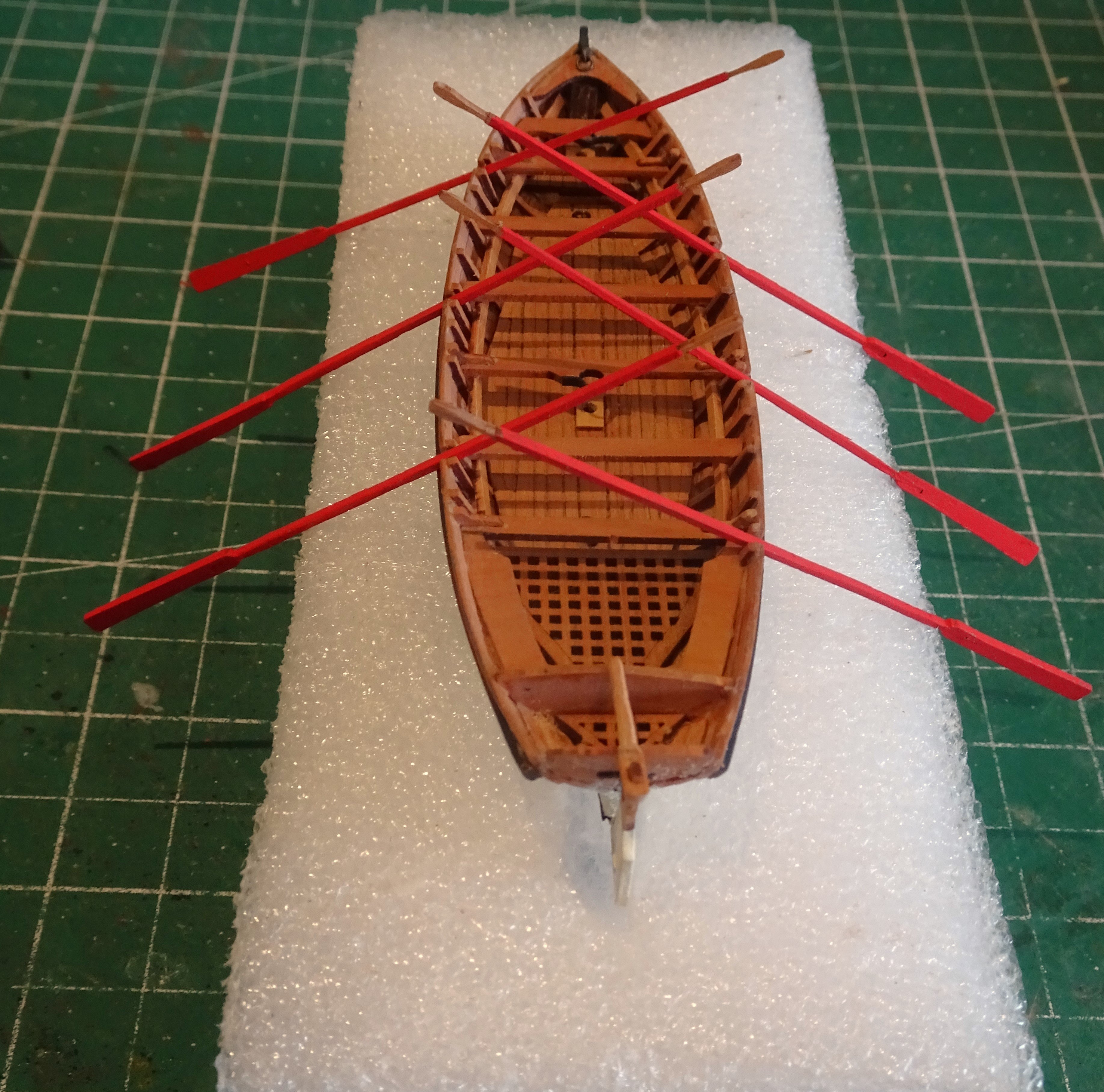
Post One Hundred and Seventy Completing the Cutter. Apart from painting the bottom Ivory, and the wale Black/grey, the boat will be finished using w-o-p only. The rudder is a plain laser cut affair intended I think to simply display in the sternsheets of the boat. There are no fixings to hang the rudder either on the stern post, transom, or rudder. I chose to add these fittings including a tiller of the yoke type. 4287 Still requires a little further fining down, this is the third attempt which may still break. 4289 Trial fitting the rudder.; a few tweaks required. One consequence of changing the rowing arrangement from double to single banking is that the provided oars are too short for purpose. 4290 They are fairly easily modified but it does require using two oars to produce one. To improve the look of the oars the blades should really be thinned towards the tip. 4295 4298 4299 4311 Set -up for single banked rowing. 4302 4306 4307 I quite like the look of her on the skids and the Pinnace and Cutter don’t obscure much of the Main deck. B.E. 16/04/2024


- 648 replies
-
- 23
-
-
- Indefatigable
- Vanguard Models
- (and 1 more)
-
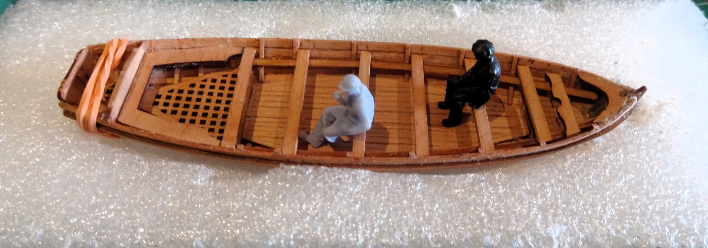
Thank you Nils and Nipper. @ Nils - the figures are industrial workers which I found suitable for my Fishing boat models, but don't really fit naval figures of the early 19th century. @ Nipper - I don't really like action figures on my models, but I do like figures to demonstrate scale on a model. I agree the cook and the Pellew/Hornblower figures fit that bill perfectly. Others that would appeal to me would be a Helmsman standing by the wheel, and a Marine Sentry to post outside the Captains Quarters. I'm not holding my breath tho'😉 B.E.
- 648 replies
-
- 7
-
-
- Indefatigable
- Vanguard Models
- (and 1 more)
-
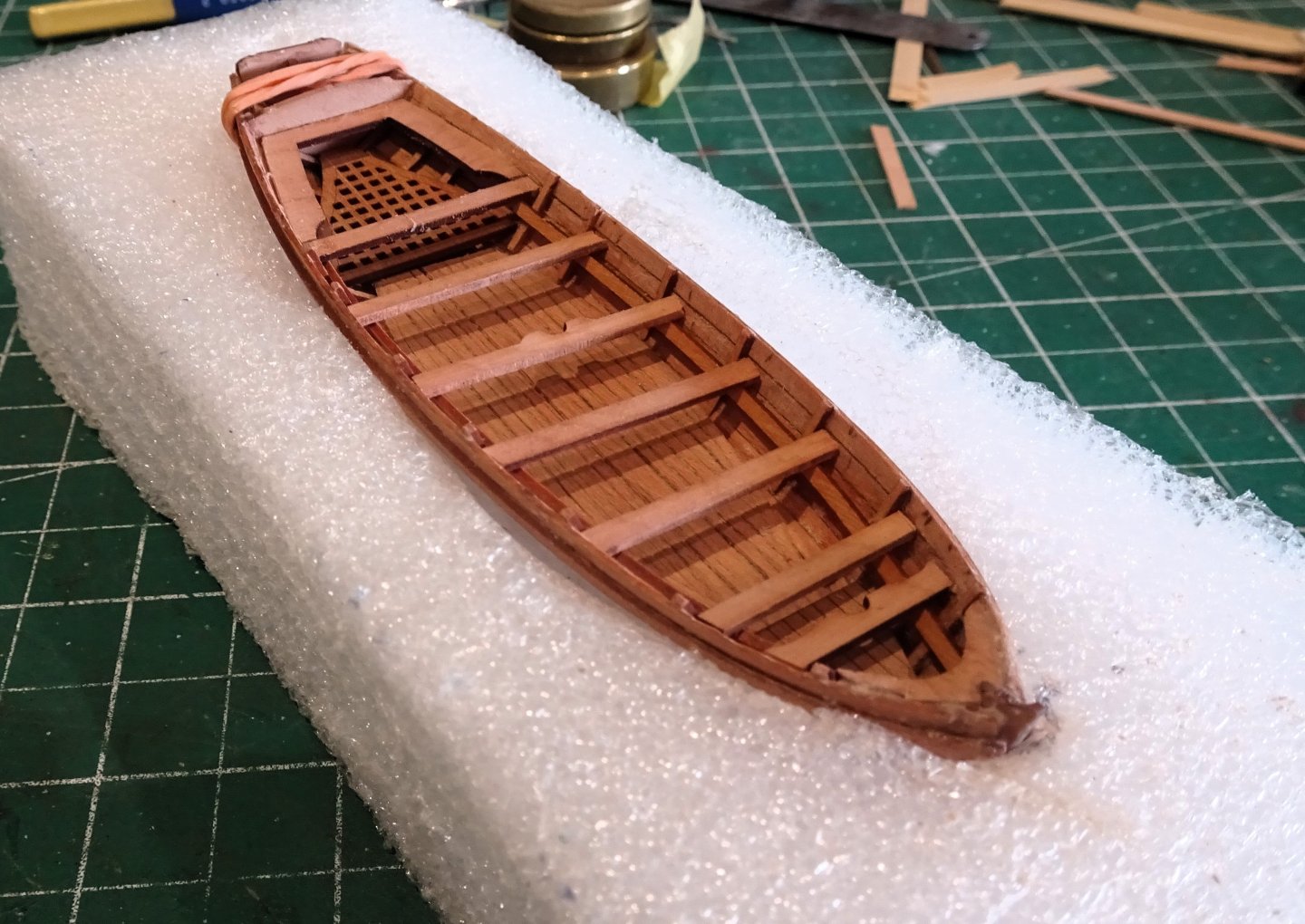
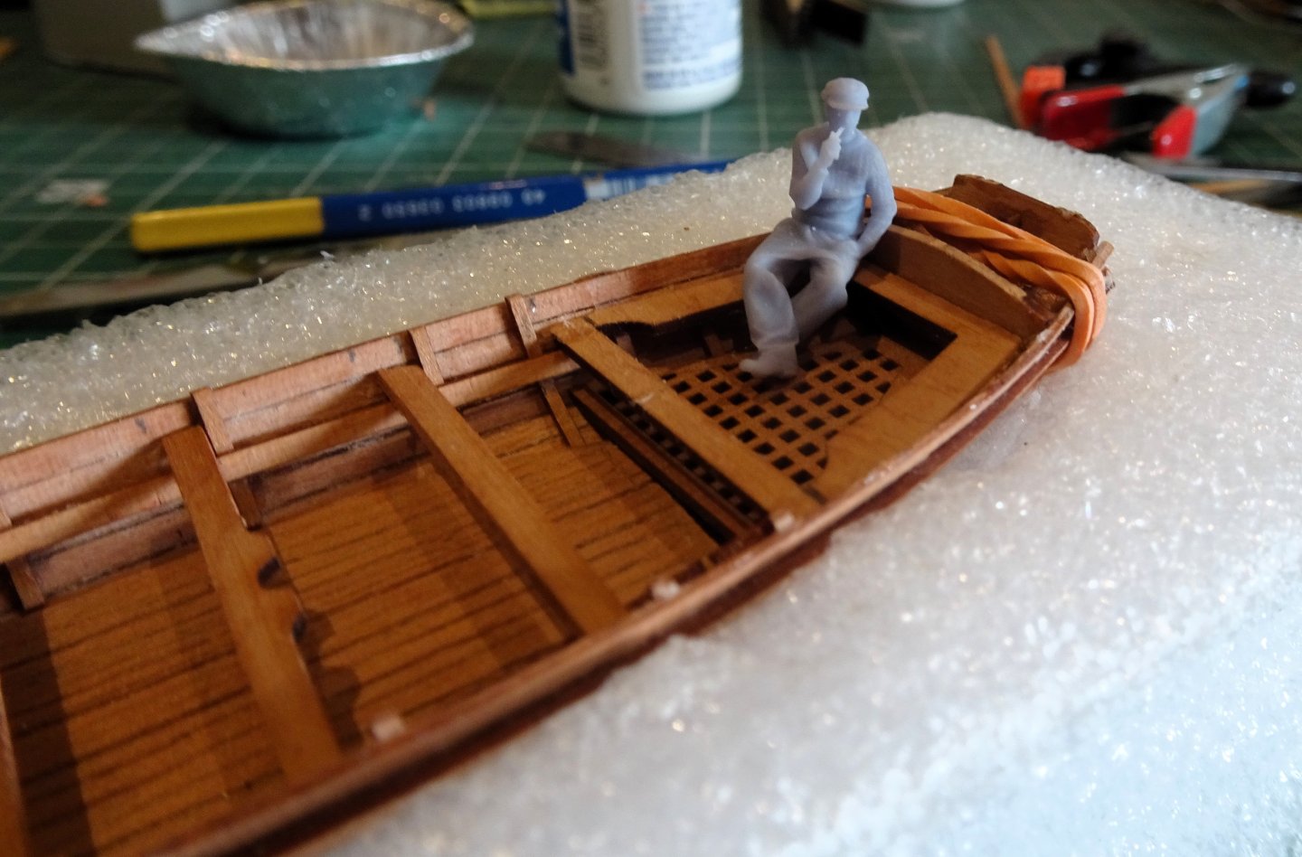
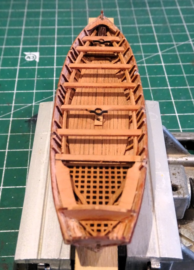
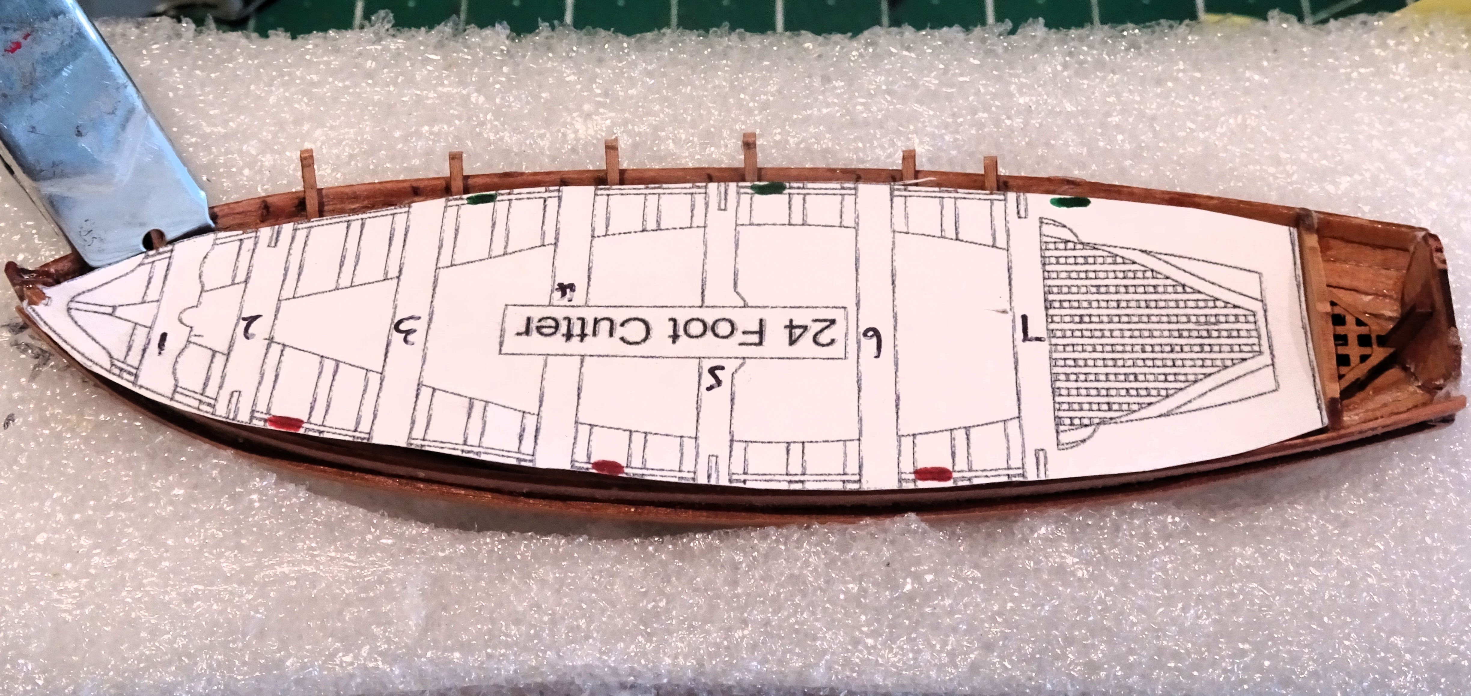
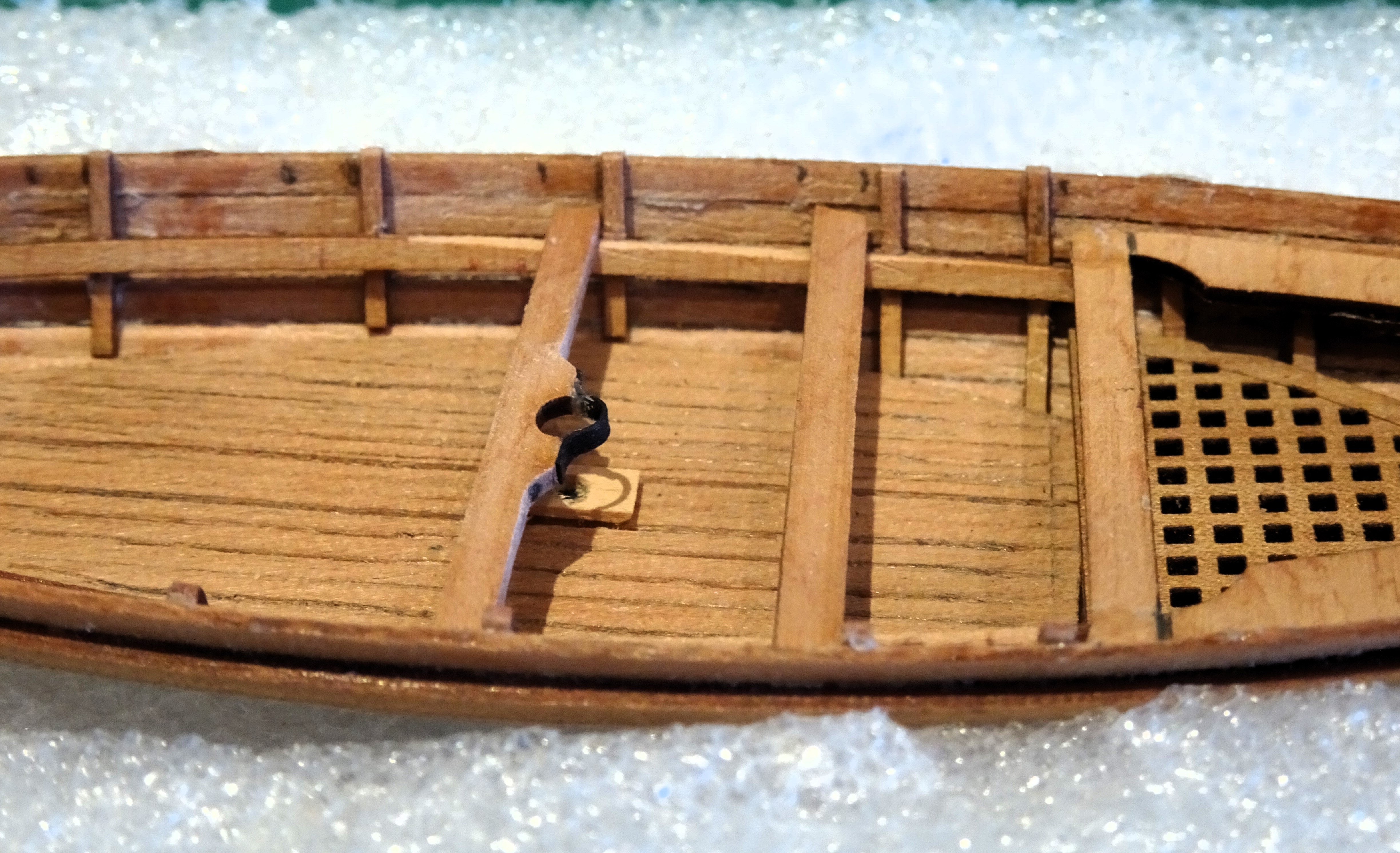
Post One Hundred and Sixty – nine Progressing the 24’ cutter The floor of the cutter is covered by gratings at the stern, open boarded footwaling for the body, and a small close board platform at the bow. 4265 I changed the footwaling to a close boarded version as shown in the AotS book Diana which contains 1:48 scale drawings of a 24’ cutter. Before I add the ‘false’ ribs I use a copy of the kit plan to mark the positions of the thwarts. Positioning the ribs really needs to take into consideration the position of the thwarts and the related rowlocks for the oars, which are cut into the wash strake. 4268 The AotS drawings show the 24’ cutter arranged for single banked rowing. This is the arrangement I will follow, apart from any other consideration, there are less rowlocks to cut. 4270 I firstly fix only those ribs that fit aft of the thwarts before fixing the Rising, (thwart support strips) The remaining ribs can be slotted behind the Risings in the correct positions. The risings are fitted using a 4mm depth gauge but in fact follow the line of the second strake down from the top. Once fitted it is useful to check both the levels and the correct height of the thwarts above the footwaling. 4273 My 1:64 scale figures are useful for this purpose. 4275 I would like to see a sitting figure produced by Vanguard. A sitting Captain would serve well to give scale to the splendid Vanguard cabin furniture, and also the stern sheets of the boat range. 4277 I like to add small features to the boats such as here; the cap square for the Mainmast and step to take the mast heel on the Keelson. 4279 4280 4281 4280 Needs cleaning up now before finishing. B.E. 15/04/2024


- 648 replies
-
- 25
-
-
- Indefatigable
- Vanguard Models
- (and 1 more)
-
I gently rub the base on sandpaper until it is very thin, and then snip around the feet with sharp cutters, I suspect using a dremel would be overkill. B.E.
-
I've not seem a specific reference to Foreign Service locations, but I suspect it generally meant any location beyond home waters , particularly the tropics where repair facilities may be restricted. Clinker built boats were more difficult to repair and WE May (The boats of men of war) cites that in 1800 it was decided that the only cutters to be sent abroad should be Jolly boats. Navy board orders to Dockyards PRO adm 106/2512 no's 430 440/441. For the purposes of this build the cutter will be issued as carvel built. 9898(2) 9899(2) I do however, have a clinker built 18' cutter (Jolly Boat) ready to serve. Cheers, B.E.
.thumb.JPG.1fe555079f45e852d6083f8352b9e31b.JPG)
.thumb.JPG.08104c5c6d8b2aa5e37ad404b4d53030.JPG)
- 648 replies
-
- 23
-
-
- Indefatigable
- Vanguard Models
- (and 1 more)
-
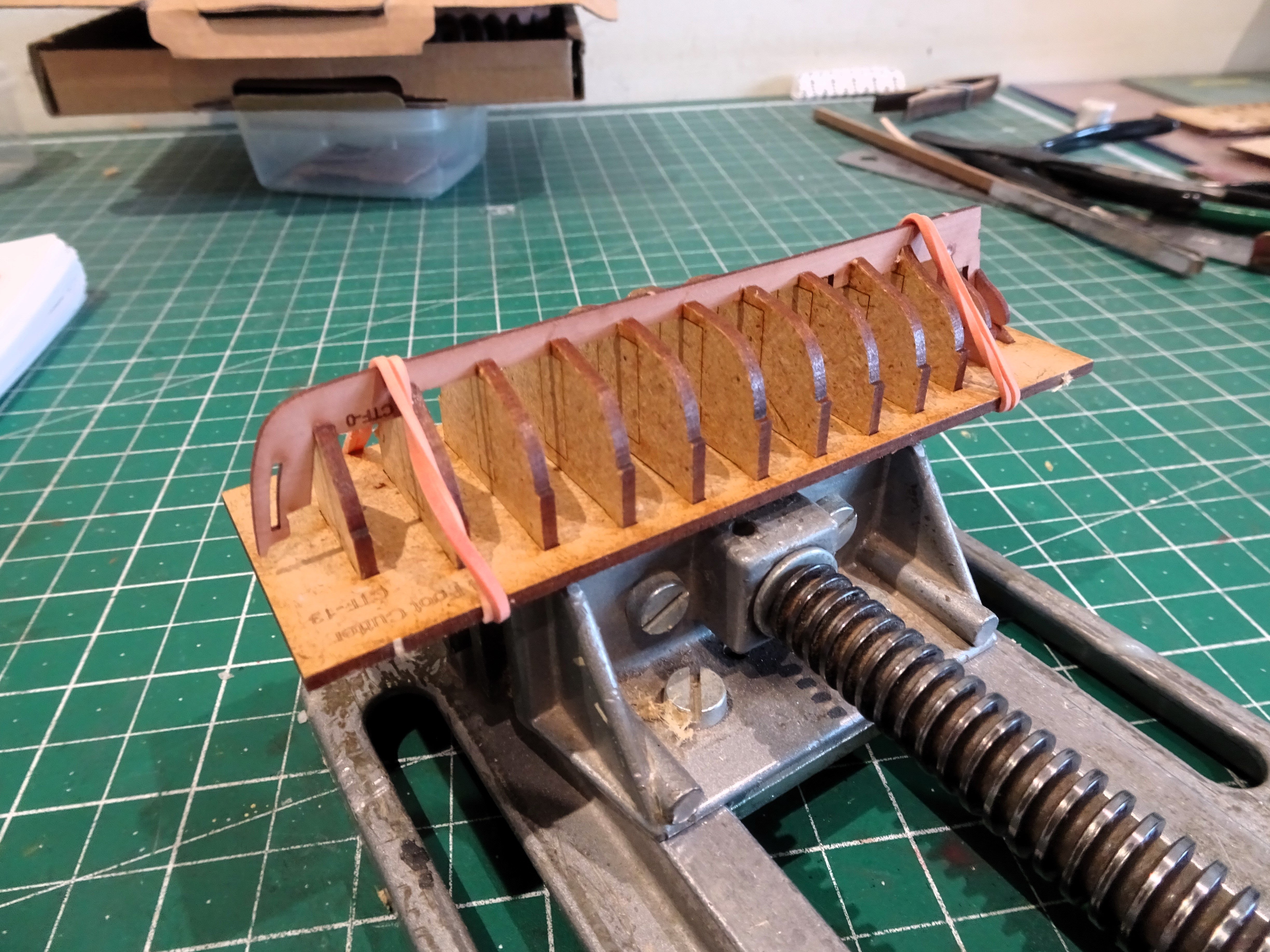
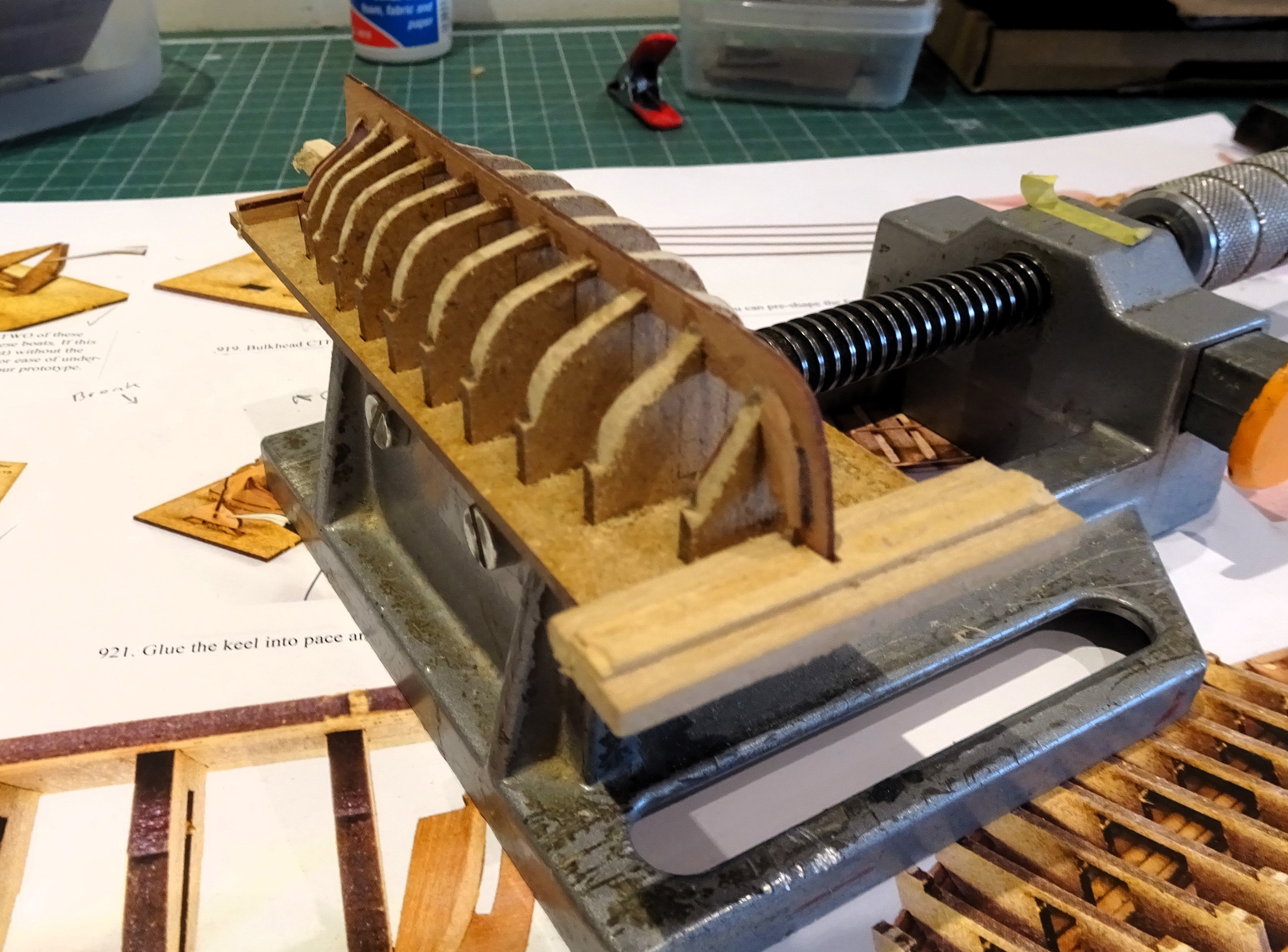
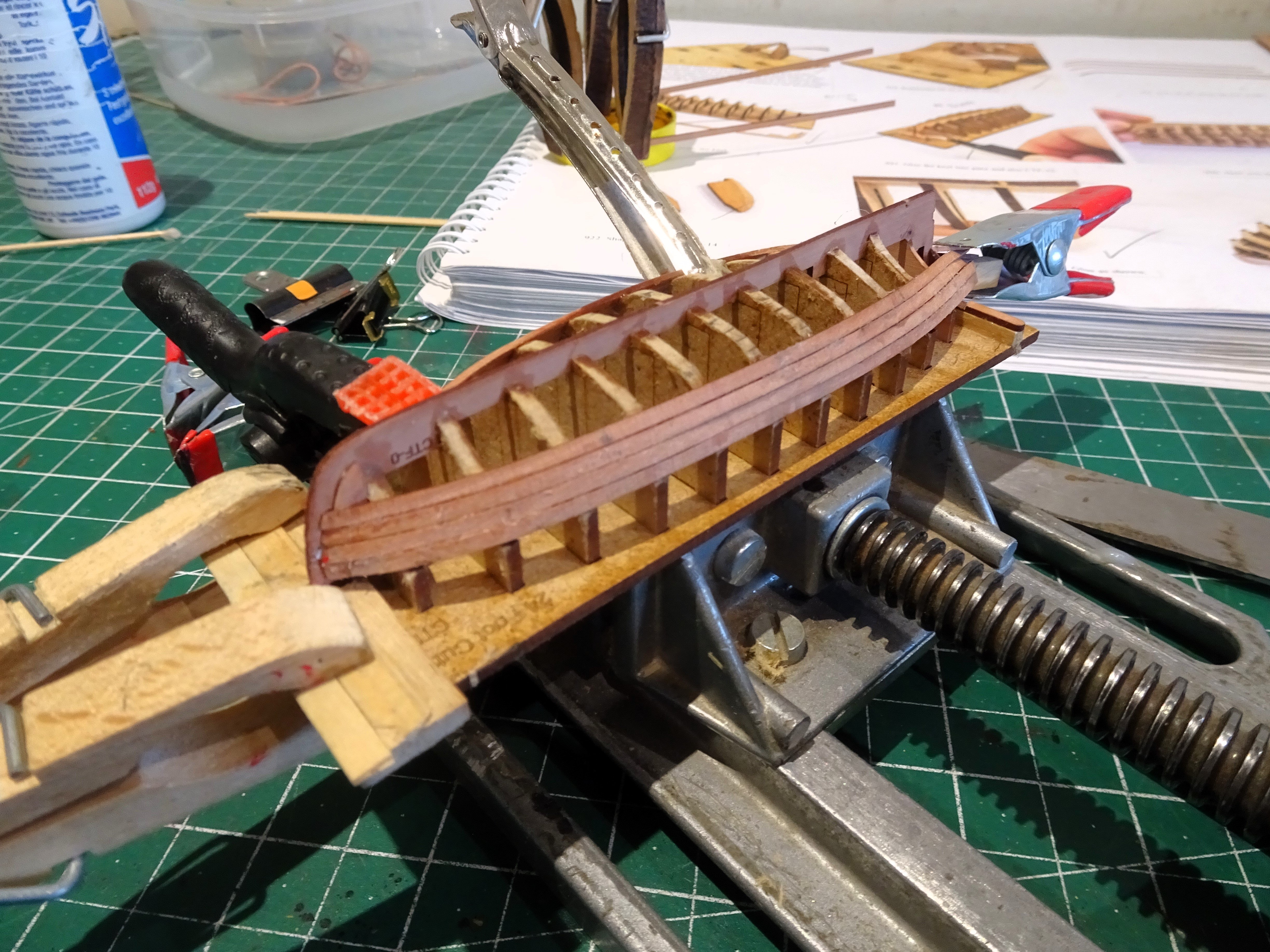
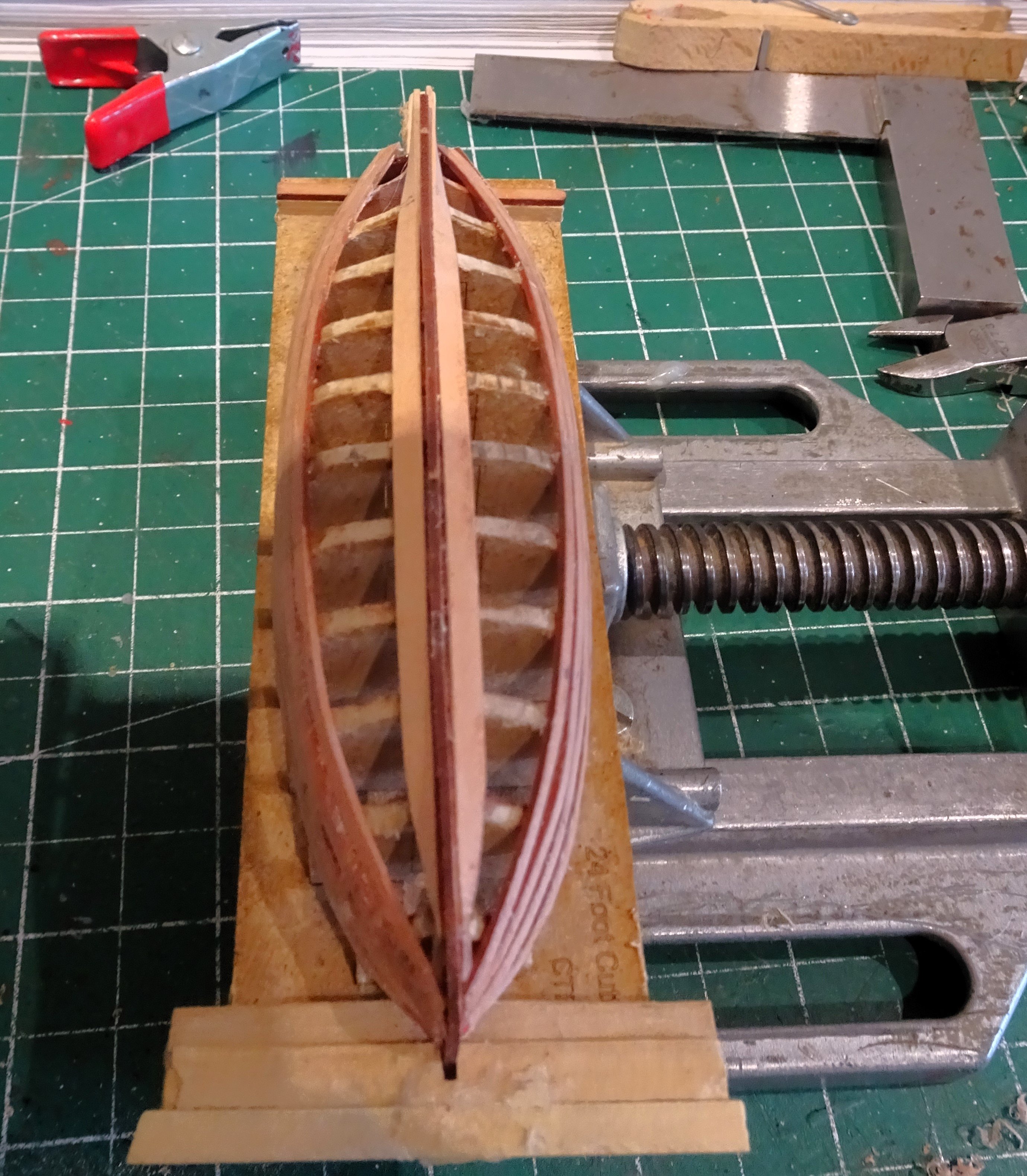
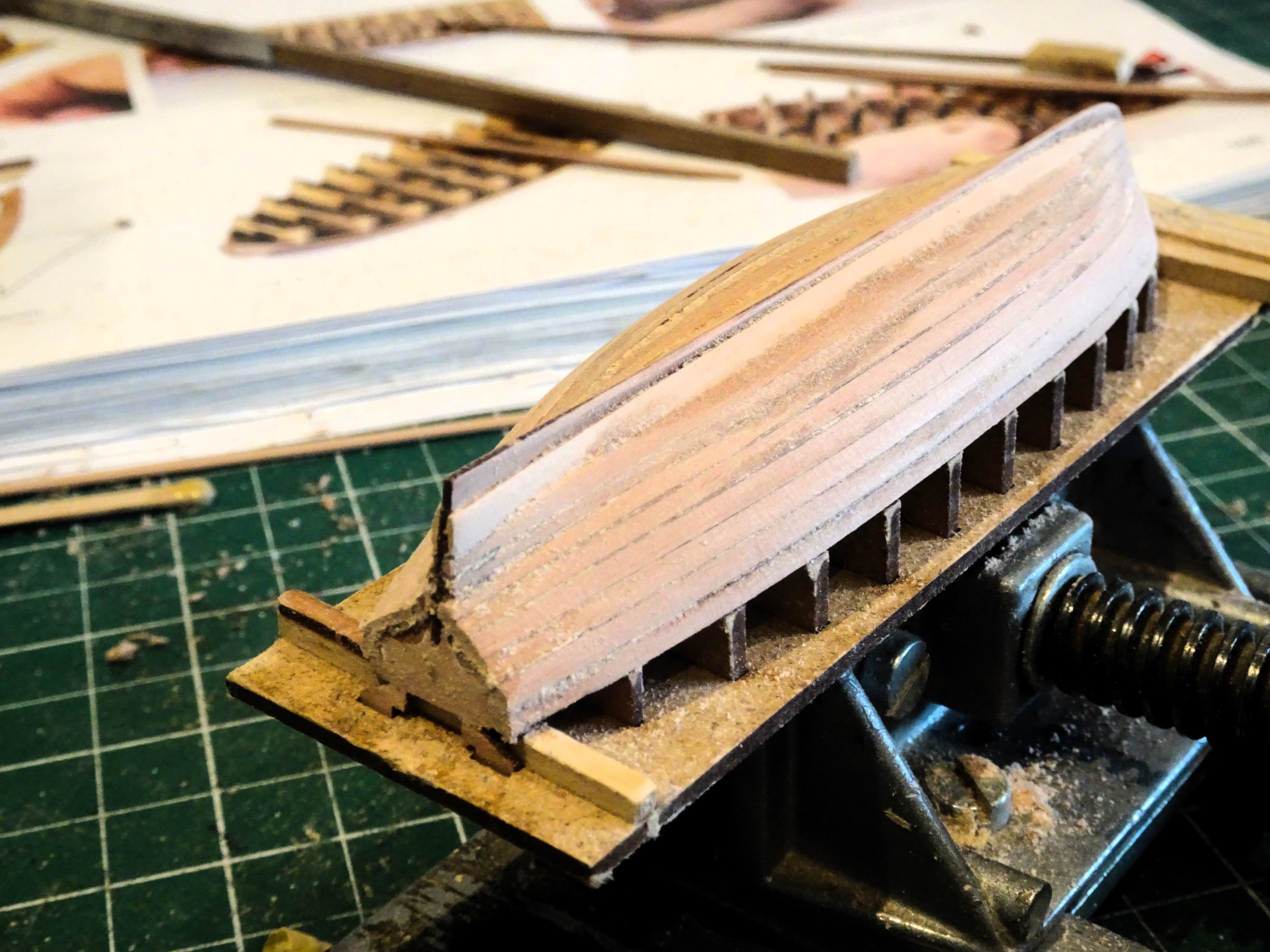
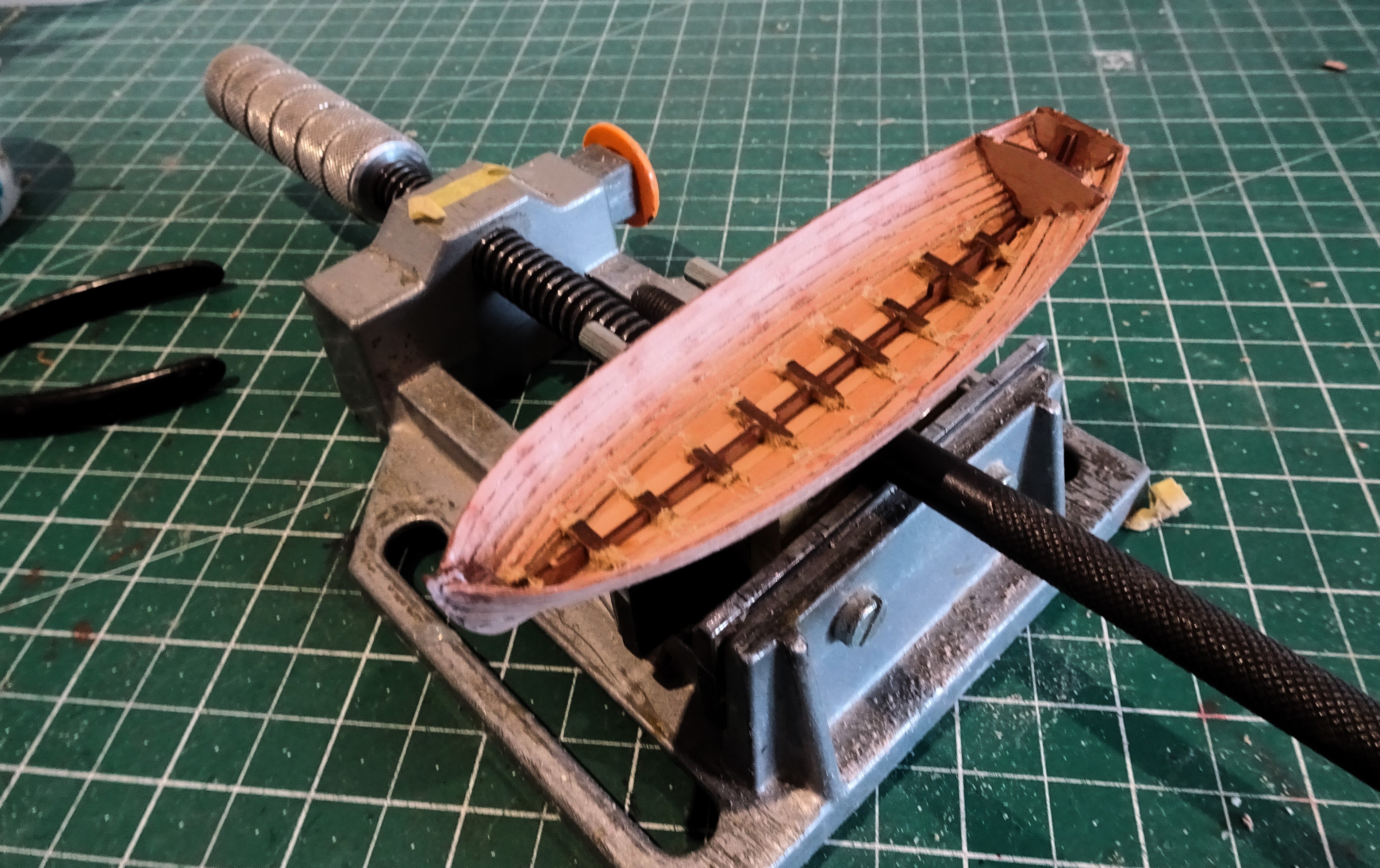
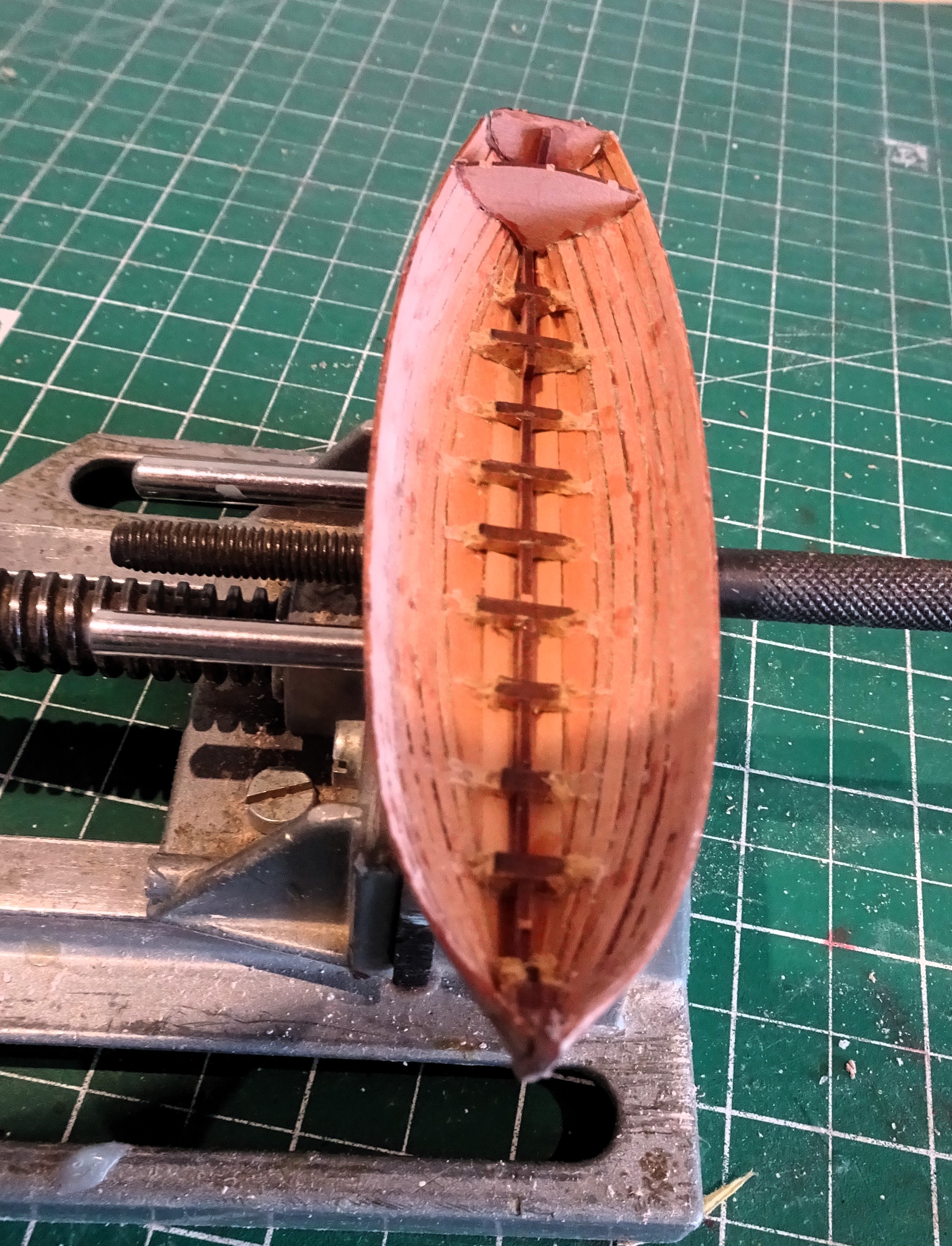
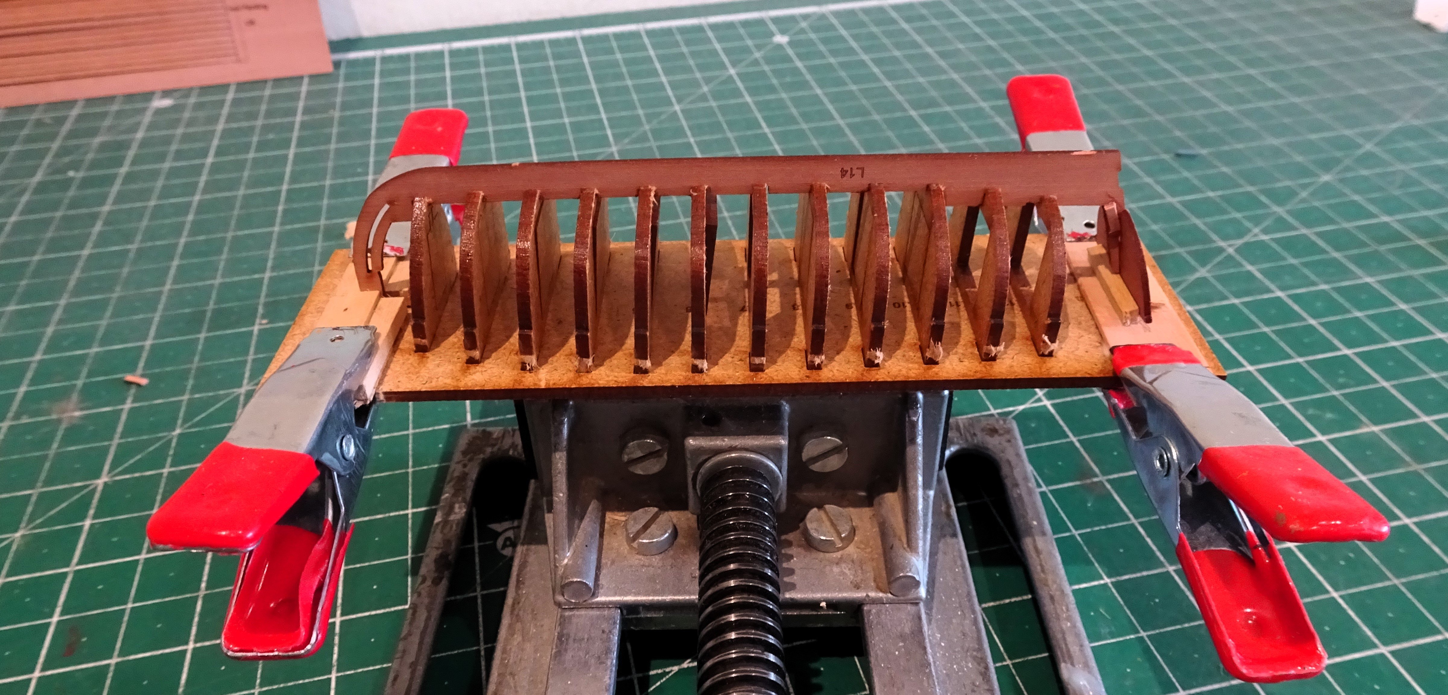
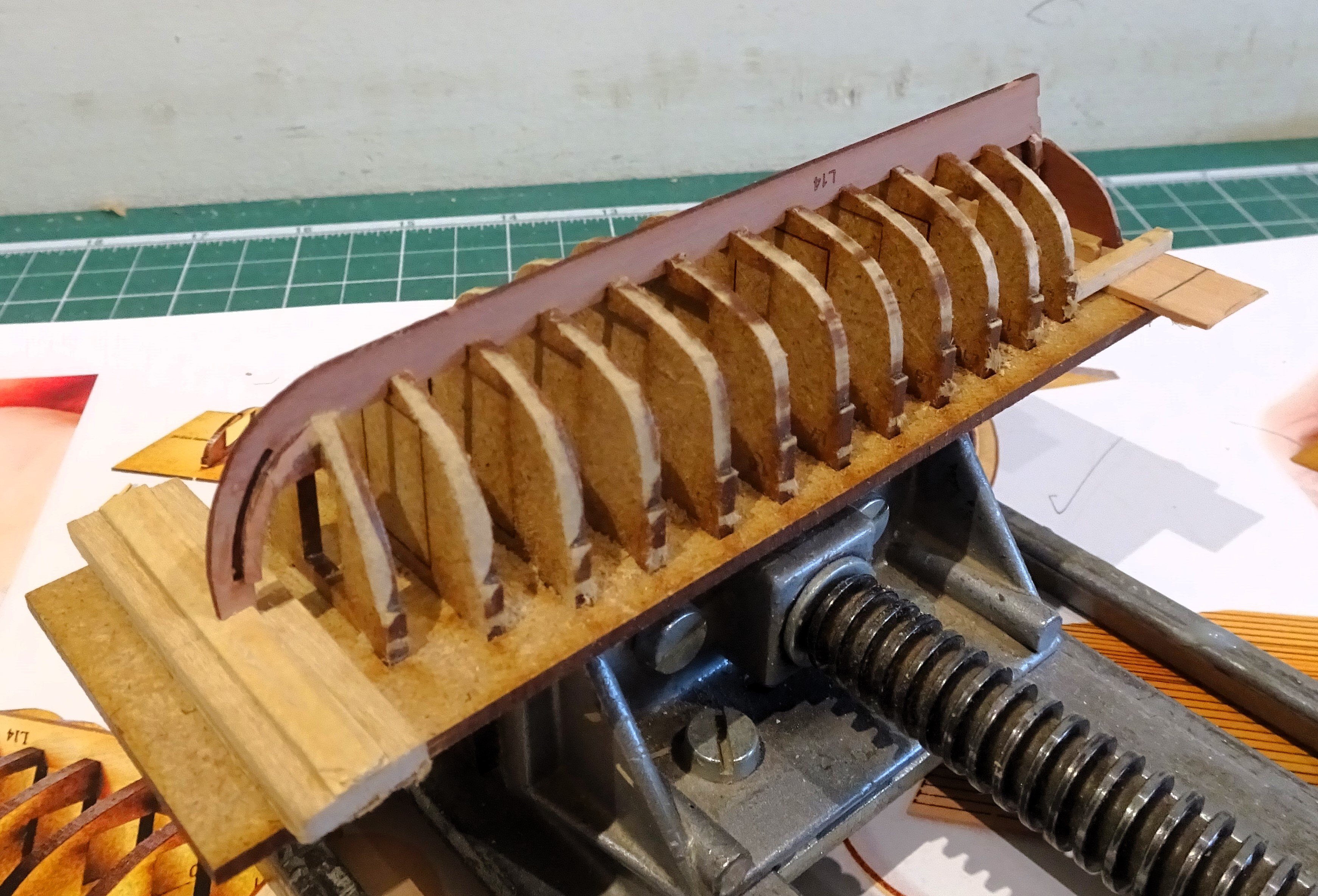
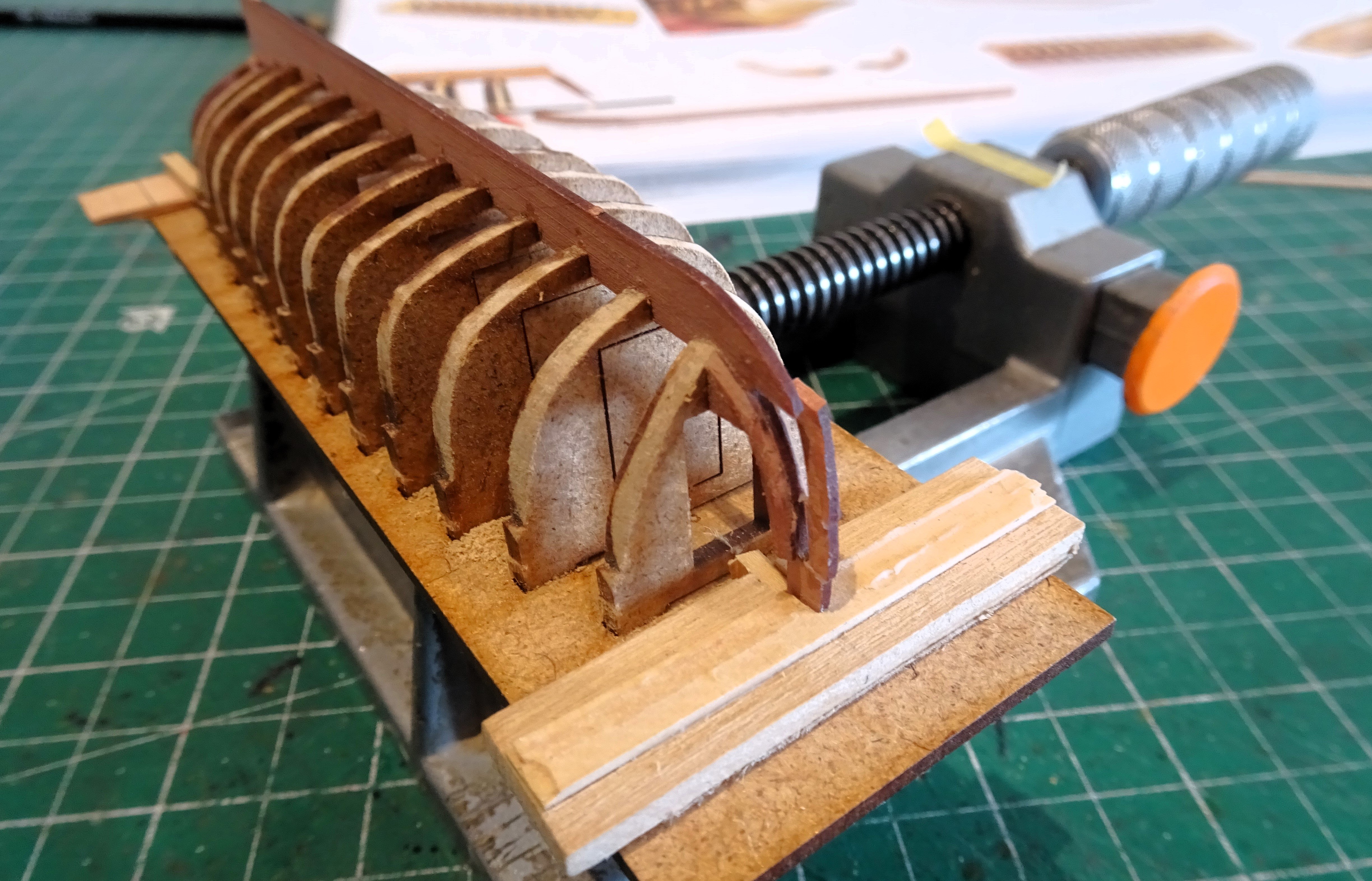
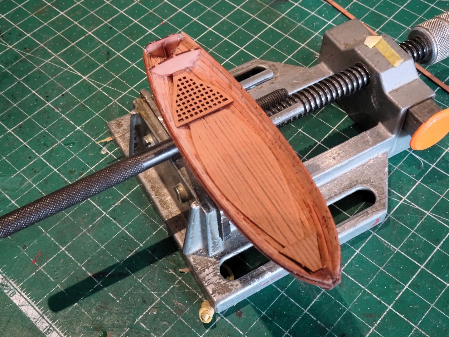
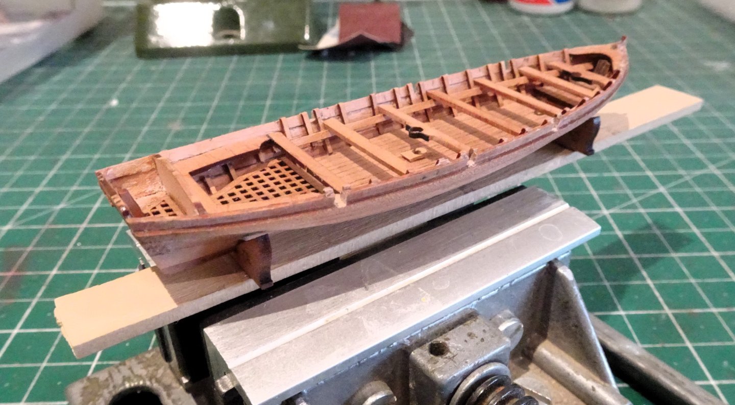
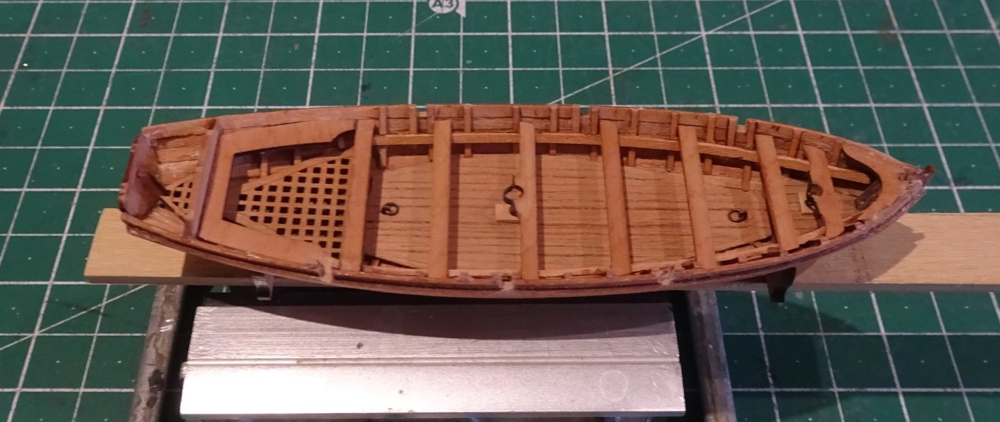
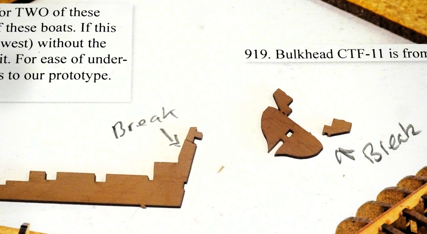
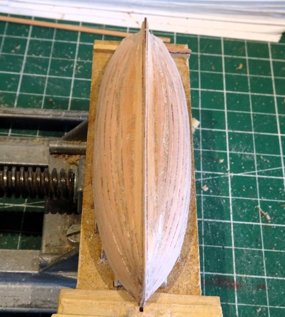
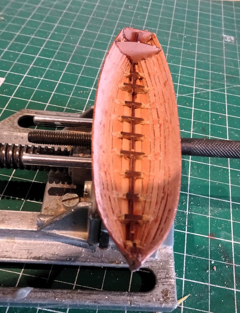
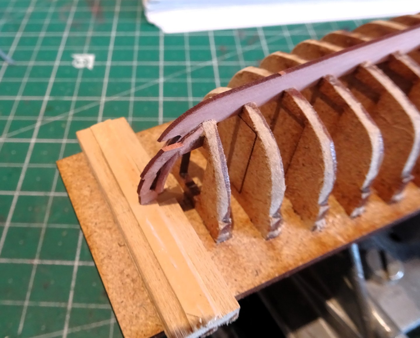
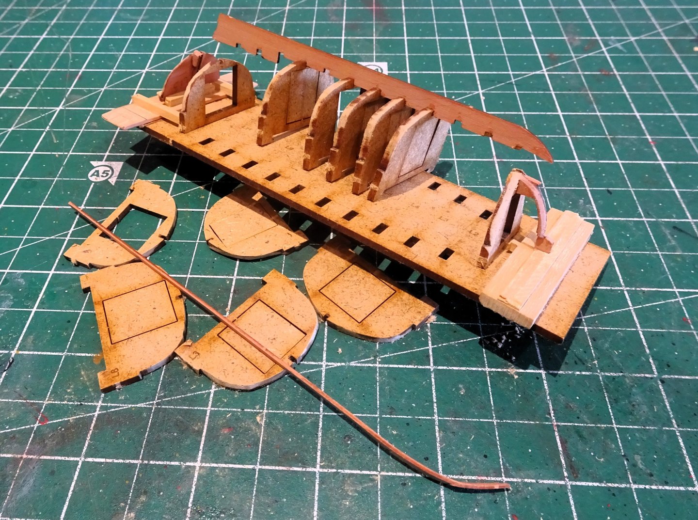
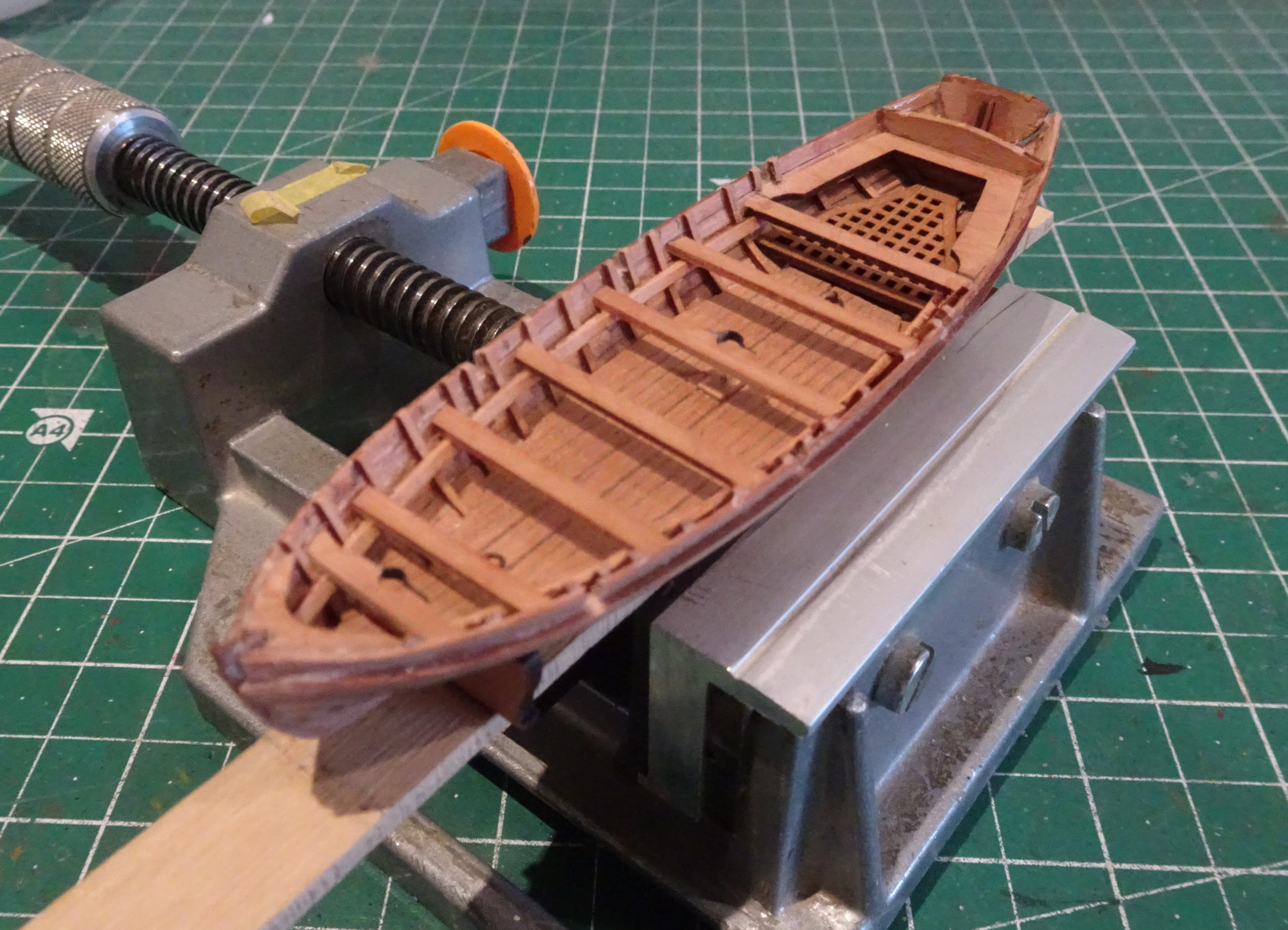
Post One Hundred and Sixty-Eight Feeling somewhat miffed about the failure with the Launch I am moving onto one of the 24’ Cutters, if for no other reason than ‘getting back on the horse’ I have made 18’ Cutters previously, along with Yawls, and a 24’ Cutter should at least on paper be less fiddly. 4245 Before I had barely got started the tab broke off the transom piece, and once again the stern post broke part way up. This is before I even get to the delicate stem with its planking slot. I am beginning to think that use of 0.8mm Pear is just too thin for the structurally important keel part. It is pertinent that the grain on these parts is horizontal whereas any pressure tends to be lateral. It seems that any pressure, however light, gives a high risk of breaking these parts. 4243 At least with the 24’ cutter there are two sets provided, and in my case one was cannibalised to get to the keel and frames assembled. 4248 With the fairing completed this is the same point at which things went wrong with the Launch. I added further support to the stem before I began planking, and this time I resolved to use pva on the plank edges in addition to ca on the frames. 4252 The first four planks fit into the stem rabbet, or slot, happily without mishap this time. At this point the structure is much stronger, and damage risk to the stem much reduced. 4254 The garboard planks are fitted using 3mm strips. 4256 There is too little room to follow any sort of tick marking for plank shaping, so its basically done by eye. The aim is to get any less than realistic planking strakes below the round of the hull, out of sight. 4258 I achieve this by spiling the last plank. Unlike the Pinnace, removal of the central bulkheads did not result in disassembly of the planking, no doubt due to adding pva along the strake joints. 4259 There is no access to clean inside glue stains during construction so there is inevitably marring present once the bulkheads are removed. 4260 A gentle approach is necessary, I clean the insides initially by damping the excess glue with a small paint brush and gently scraping with a micro chisel. Water is used for the pva and acetone for the ca. very small amounts are used to avoid affecting the main construction. A little more fettlin’ and I can move onto the next stage. B.E. 11/04/2024


- 648 replies
-
- 16
-
-
- Indefatigable
- Vanguard Models
- (and 1 more)
-
I like the muted tones, and a good decision to dispense with any bling. I also very much liked your Diana which I can see in the background. Cheers, B.E.
-
Magnificent work Jason, that is truly impressive. B.E.
-
....... or not as the case may be, we will see.
- 648 replies
-
- 2
-
-
- Indefatigable
- Vanguard Models
- (and 1 more)
-
Thank you Mark, and Ron, It still rankles Ron, moving onto the 24' Cutter, we'll see how well I can mangle that one.🫤 B.E.
- 648 replies
-
- 4
-
-
- Indefatigable
- Vanguard Models
- (and 1 more)
-
Perseverance pays off David, well done👍 B.E.
-
Post One Hundred and Sixty-seven The 26 ft Launch - The Good, the Bad, and the Ugly. Altho’ the main work on Indy has been completed, the overall display requires further work. Building the Launch continues my work on the boats. I like the Launch because it offers opportunity to add detail such as the windlass. I have been here before as I made up the 24’ Launch for Sphinx. This didn’t however guard me against breaking the stern post (twice) during the fitting of the transom. 4227 Again, I thought it prudent to add little support pieces to the build board to reduce any flexing during the fairing business. These small boats are delicate and require gentle handling particularly in the early stages. 4232 The fairing went ok. 4235 Regrettably, the stem broke in two places along the planking slot during the testing of the first planking strip, hardly touched it Gov’ner, and the repairs didn’t hold. 4236 I suspect it was a combination of the inherent weakness related to the planking slot, plus possible grain run of the stem. 4239 I did think about replacing the stem element, but removing the frames from the base resulted in what our American friends may describe as FUBAR. Sadly, Indy will be without her Launch, but stuff happens – right. B.E. 07/04/2024


- 648 replies
-
- 18
-

-
-
-
- Indefatigable
- Vanguard Models
- (and 1 more)
-
So sorry to read this Kevin, For what it’s worth, hard as it is, I think you are making the right decision. We invest so much in our cocker family members, and the pain we feel when their time comes is very real. I know you will do right by Dobbie. B.E.
- 443 replies
-
- 3
-
-
- Indefatigable
- Vanguard Models
- (and 1 more)
-
Thank you Glenn, I'm going to finish off the Indy boats; doing well so far, I've already snapped the stern post of the Launch twice in fitting the Transom.🫤 After that it's back to Syren, to finish Chuck's wonderful Medway Longboat. Regards, B.E.
- 648 replies
-
- 5
-
-
- Indefatigable
- Vanguard Models
- (and 1 more)
-
Cheers Guys, I will do a set of completion photos before I encase her, but the wooden framed glass case is very heavy compared to my previous acrylic covers, not very convenient for multiple off and ons, and all the associated risks involved. @ Bug - A lot of the deck fittings are removeable including the rope coils, so these are taken off when cleaning. I simply start at the top; firstly cleaning the rigging lines, then the masts and yards, using a soft paintbrush. For the dust on the decks I pick it up with a soft brush and suck the dust with a hand held vacuum (Dyson) I finish off the outside of the hull. Considering she has been uncased for many years she comes up pretty well, takes around 3hours + to do it. 2007a Here she is stripped down for cleaning, built at a time before the availability and quality of fittings we have today she still remains one of my favourites. Regards, B.E.
- 648 replies
-
- 17
-
-
- Indefatigable
- Vanguard Models
- (and 1 more)
-
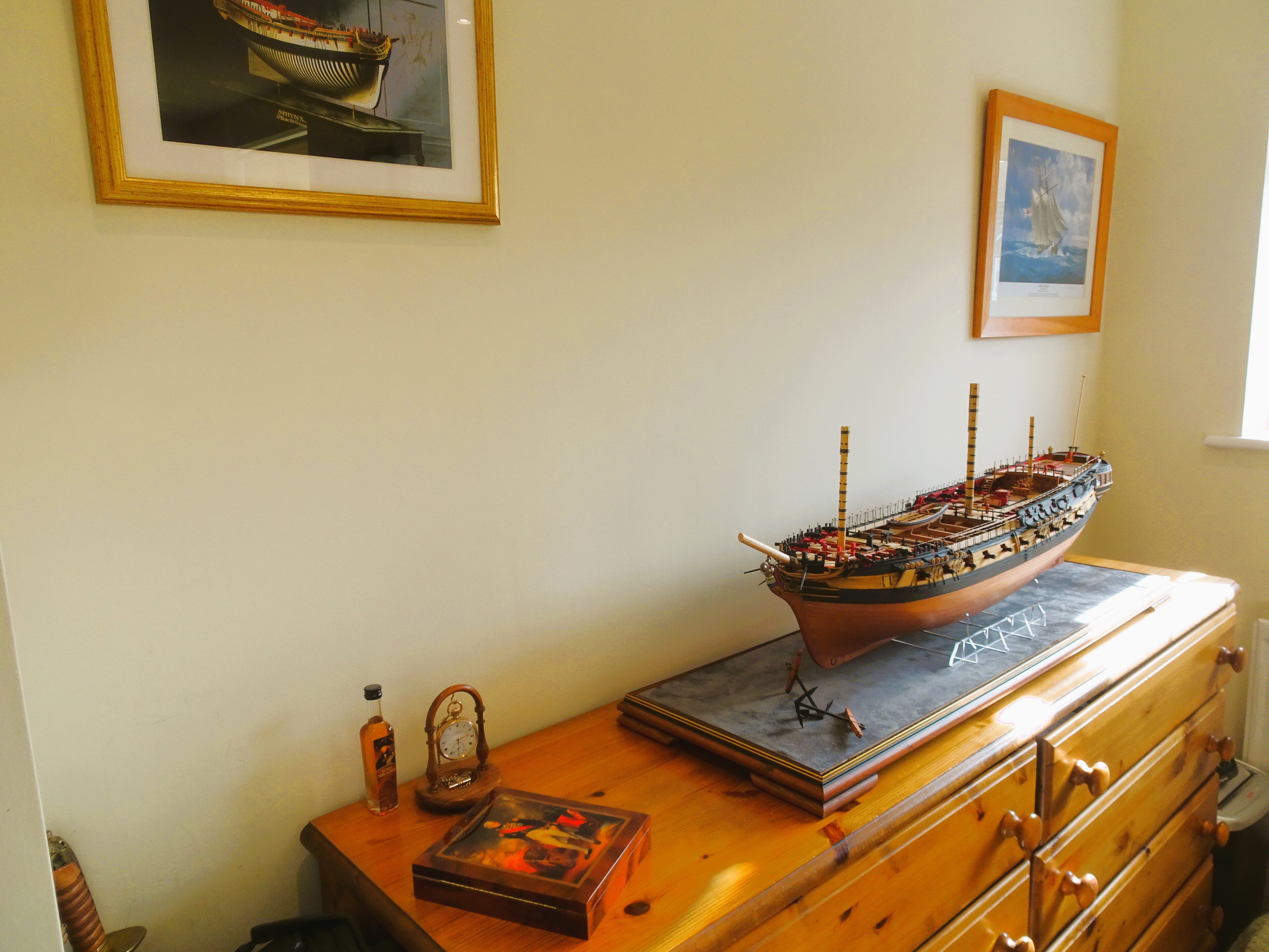
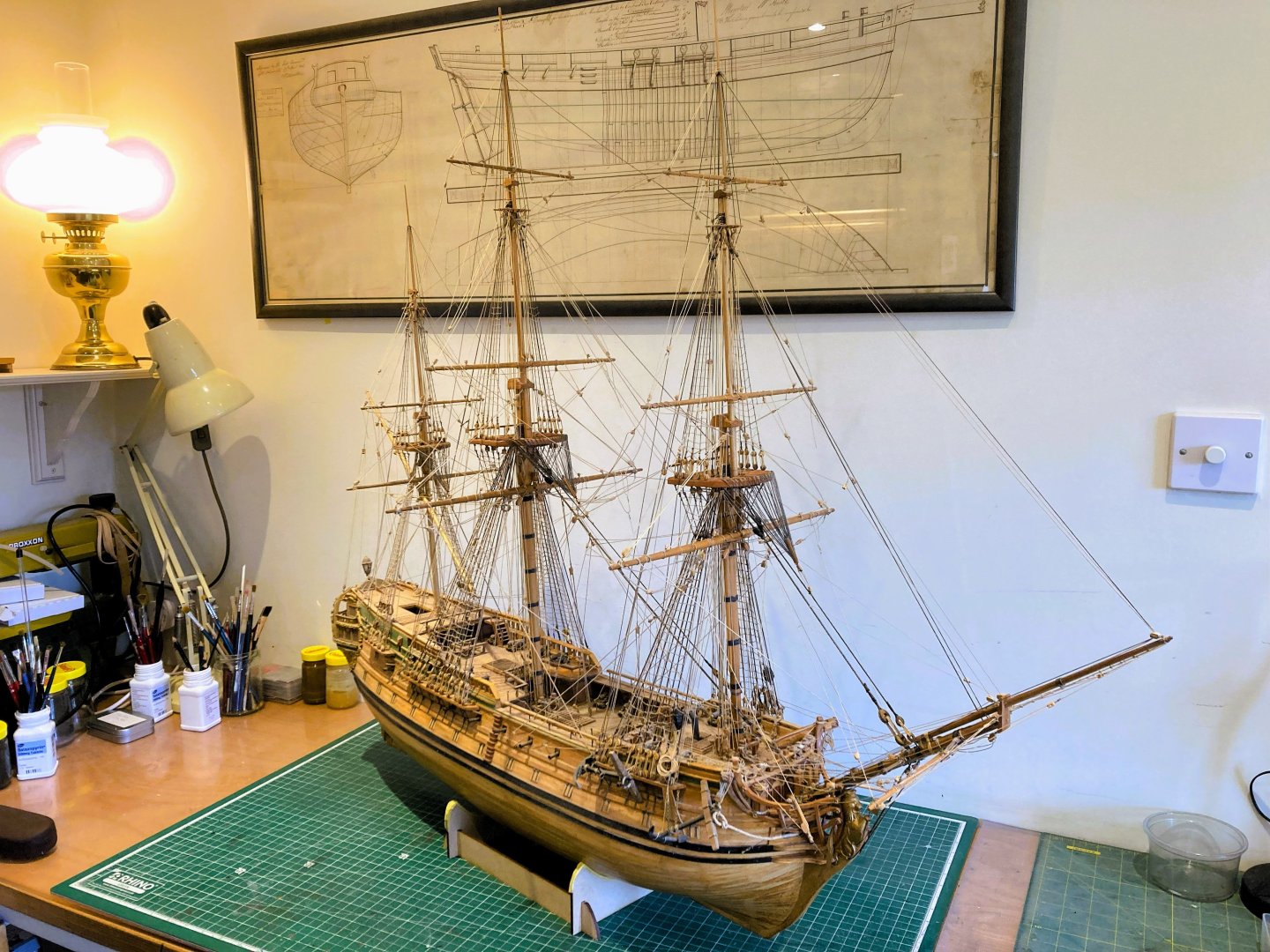
Post One Hundred and Sixty-six My version of Indy is effectively completed now and with some serious moving about of models within my workroom/office, I have found room to house Indy in the prominent position she deserves, and without encroaching on other areas of the house. 4223 She has displaced Norske Love which now has a new position vacated by Alert which also has a new location. e2008a Had I completed the masting on Indy it would be in the order of that of Norske Love which is of a slightly smaller scale of 1:70. e2012a Norske Love has received a well overdue clean, having endured all the dust created during the construction of ‘Indy’. 4022 Not quite ready for the glass cover to be on yet, but at least the issue of ‘where are you going to put that’ is now resolved. As a bonus the lower profile of Indy compared to Norske love will allow me to re-arrange the wall Pictures and perhaps get one of Indy. I have decided to have a further dabble with the boats, and have started assembly of the 26’ Launch, pity not to make them up as they are provided with the kit. B.E. 06/04/2024


- 648 replies
-
- 49
-
-
-
- Indefatigable
- Vanguard Models
- (and 1 more)
-
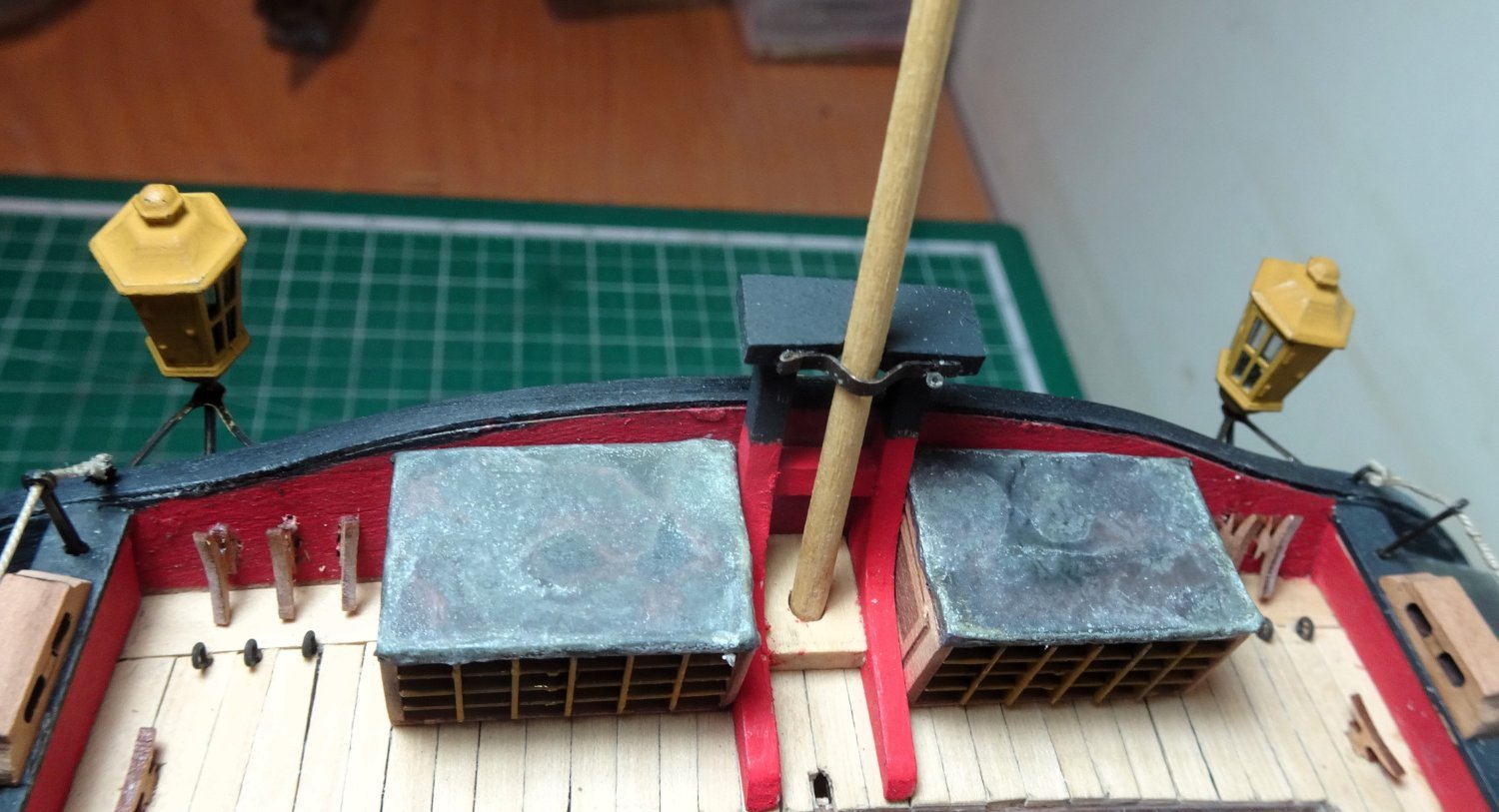
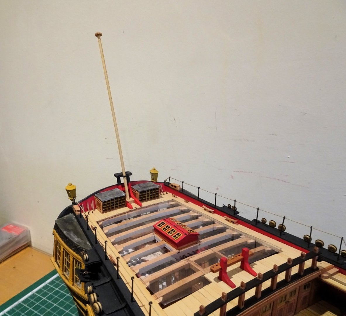
Post One Hundred and Sixty-five Thank you, Allan, the kit didn’t include any standards to support the transom, but I note that Alex M has included five in his drawings of the Anson following conversion to a Razee. He also includes an extended central standard to support an Ensign staff tabernacle. I did think about following his example but decided that the double arrangement looked more aesthetically pleasing to my eye. I think the inclusion of such an item is a reasonable assumption to make, and the set up on the Indy kit almost begged the inclusion of the arrangement as I have modelled it. 4206 4207 4217 4211 4212 4205 Onwards, B.E. 04/04/2024


- 648 replies
-
- 30
-
-
- Indefatigable
- Vanguard Models
- (and 1 more)
-
Great progress Jesse, well done.👍 Love the look of your guns and rigging. B.E.


.JPG.c02b7ca20508aa71d8b15dd2d5ada4ae.JPG)
.JPG.6a210a51353aeba2ed991c2009414a22.JPG)