.JPG.ca33079f5815b861e67b9c2cccd37982.JPG)

Blue Ensign
-
Posts
4,572 -
Joined
-
Last visited
Content Type
Profiles
Forums
Gallery
Events
Everything posted by Blue Ensign
-
 Sabotage in the Dockyard ……..and things were going so well. Until Mrs W arrives and asks is this something to do with you? 1698(2) I had minutes earlier been searching my bench and floor for a missing Window pattern. 4447 The face says it all, and the perpetrator is confined to Quarters for the present. So unless I can prevail upon Chris to supply a replacement I will have to fashion one from some scrap, and I was hoping to complete the Galleries today. Hey Ho B.E.
.thumb.JPG.5cb6145e6ee547358577bdca036f8f16.JPG)
- 857 replies
-
- 13
-

-

-

-
- Sphinx
- Vanguard Models
- (and 1 more)
-
In my own defence I merely followed the arrangement on the contemporary model Lowestoft, but as I wasn't there at the time I simply can't confirm. B.E.
- 542 replies
-
- 5
-
-

-
- Sphinx
- Vanguard Models
- (and 3 more)
-
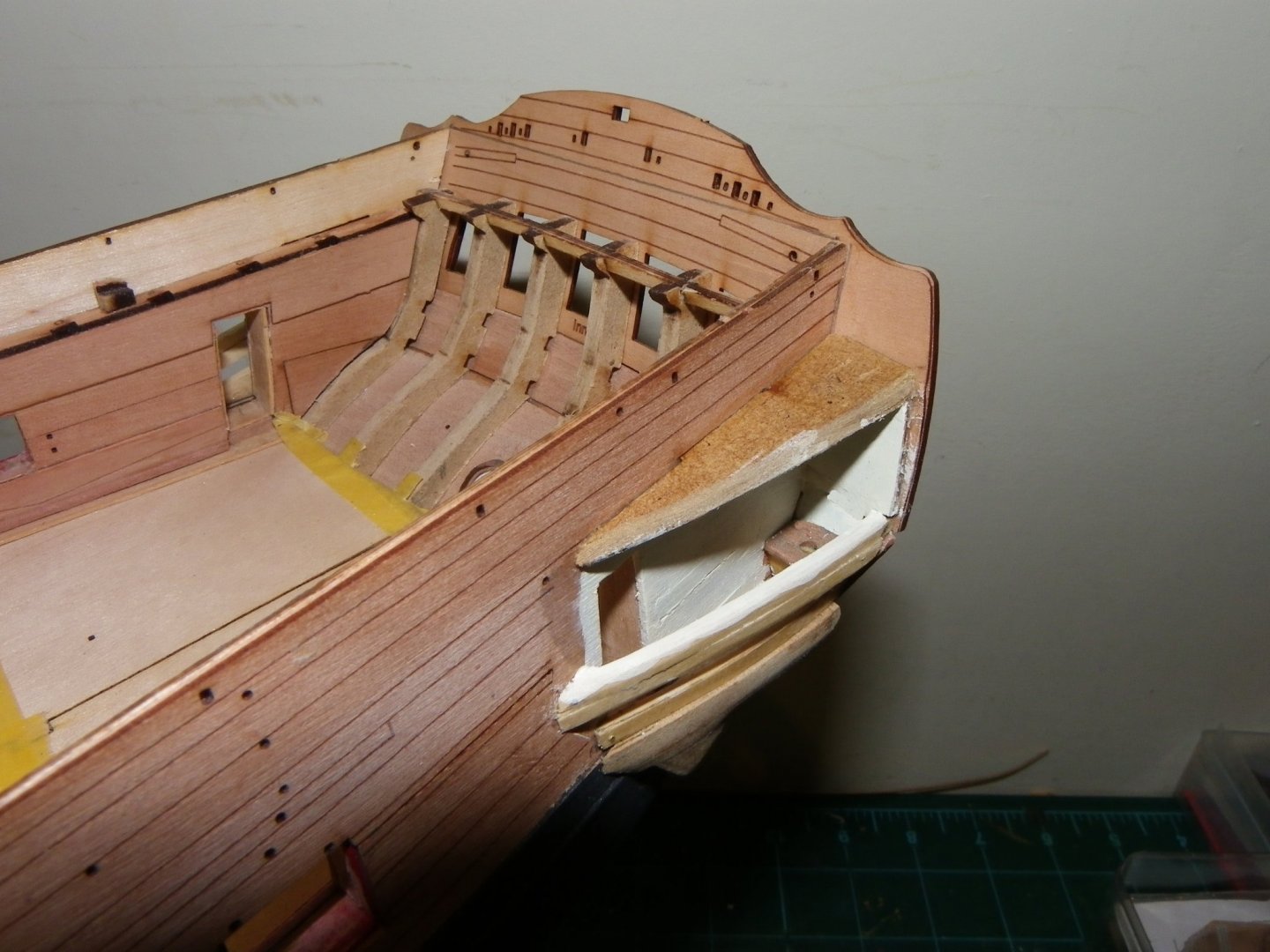
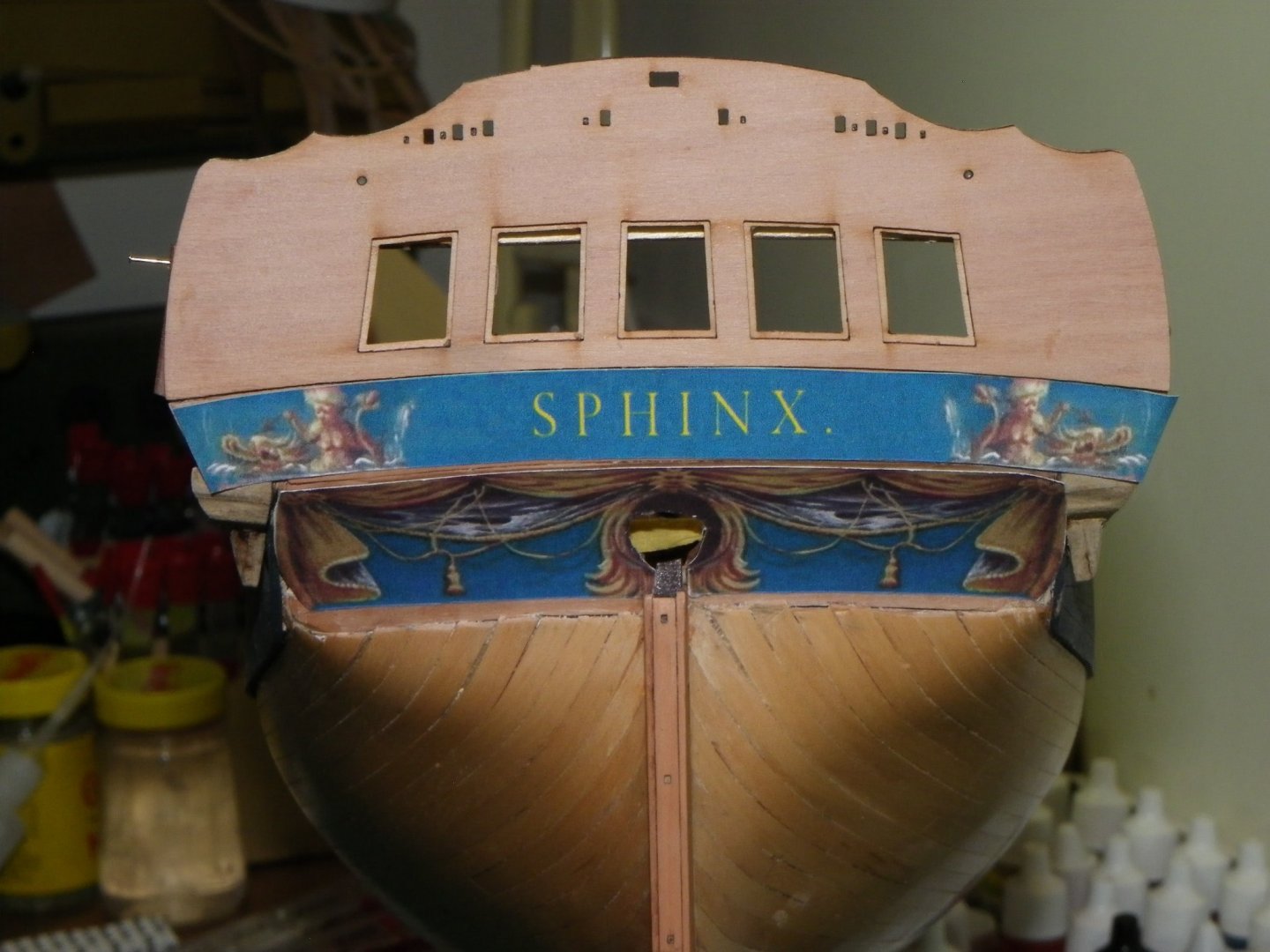
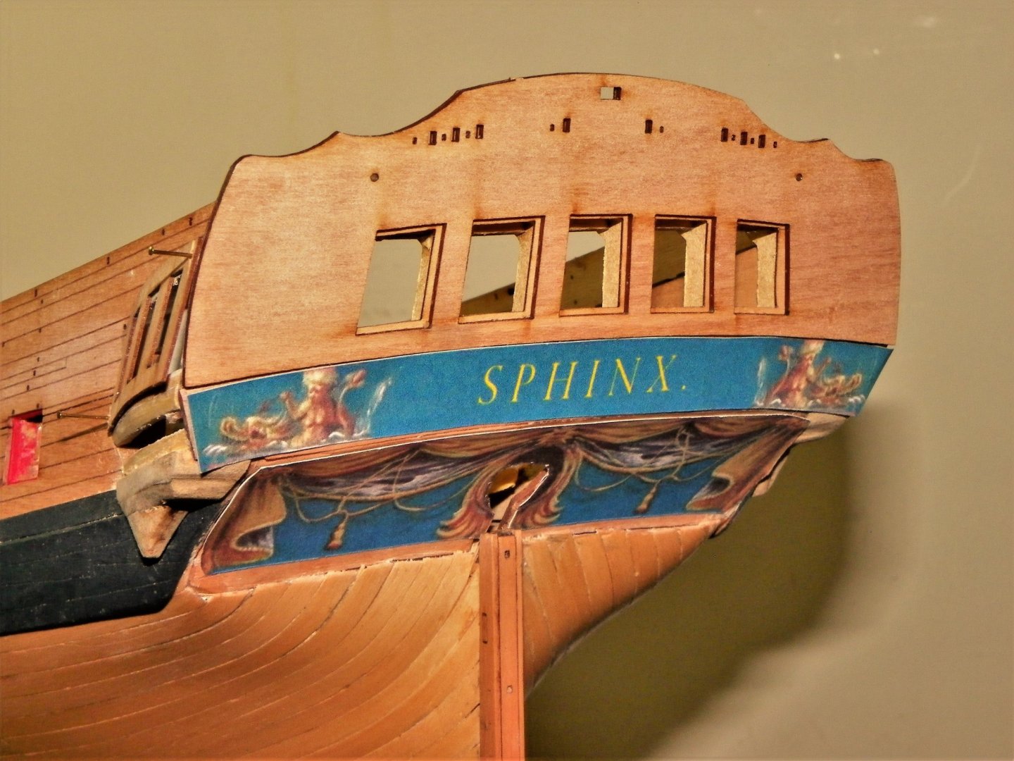
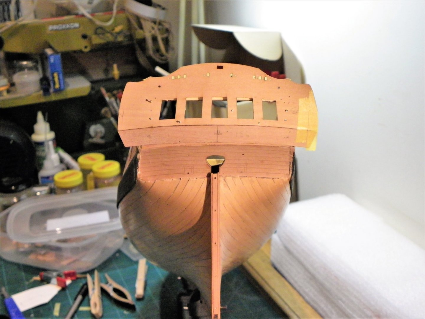
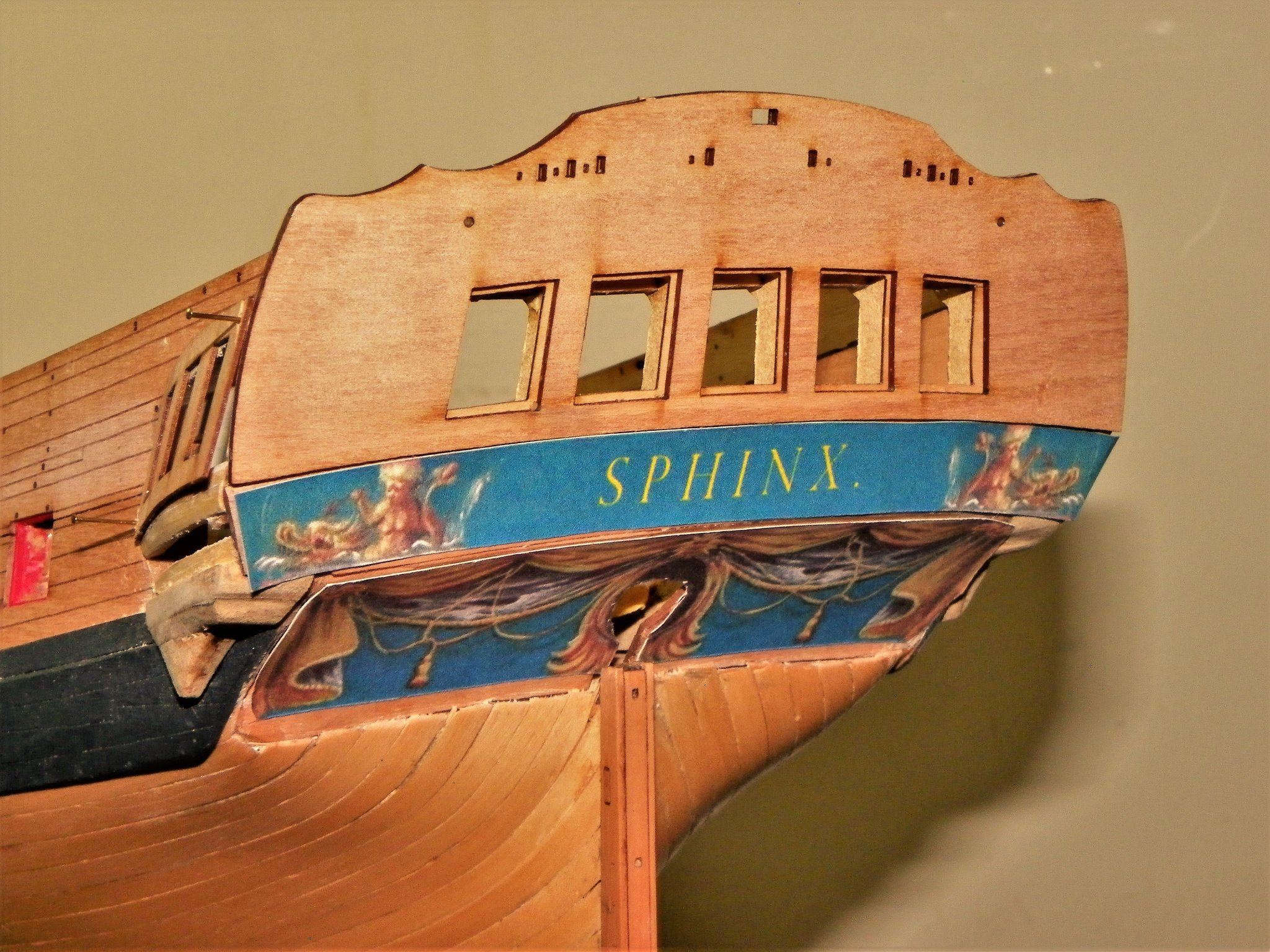
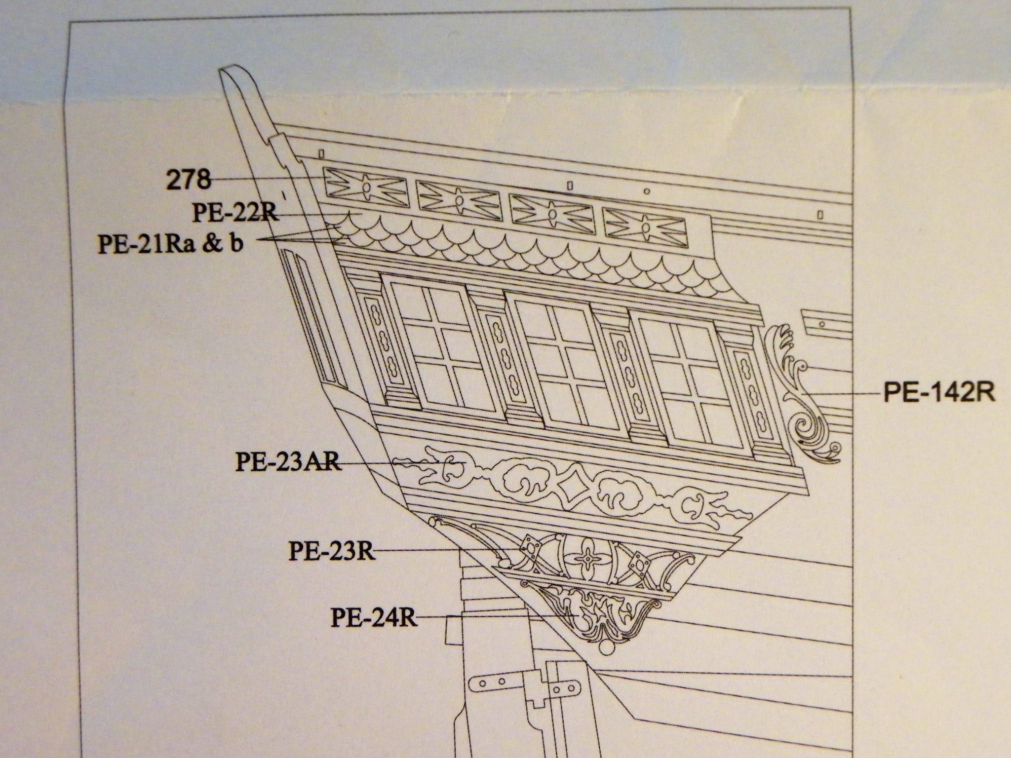
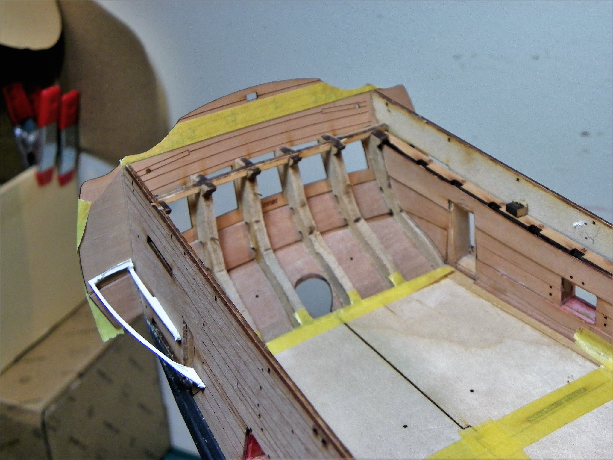
Post Forty-nine Gallery-Part three A seat of ease is constructed using Box and Pear and is fitted to the Portside Gallery. Brian Lavery (Arming and Fitting) suggested that only one gallery was fitted out as a head, the other used for storage and observation of the sails. 1652 1657 1658 I can now fit the top Qtr gallery pattern (45) followed by the outer stern facia pattern. This now protects the somewhat flimsy inner pattern. 1672(2) On the kit version inside the gallery is painted black to hide construction detail. On my open gallery style I have painted the insides Vallejo Ivory which will help light the interior. 1665 At this point I’m not sure about fitting the Upper outer counter pattern as I’m not a fan of the raised etched Name lettering provided in kits. My favoured approach is to use dry-rub lettering which has a more authentic and period look to it. I had a play around (with Chuck’s permission) using the decorative friezes and panels applicable to Winchelsea. 1689 1677 The name was replaced using Photoshop and Paint, only mock-ups at present, and the letter style needs adjusting, but I’m rather drawn to the paper frieze approach. I will return to this much later in the build. The next post will hopefully see completion of the gallery assembly. B.E. 07/12/21

.thumb.JPG.aac88e730a49eeb68b0a80f7848bb332.JPG)
- 857 replies
-
- 19
-
-

-
- Sphinx
- Vanguard Models
- (and 1 more)
-
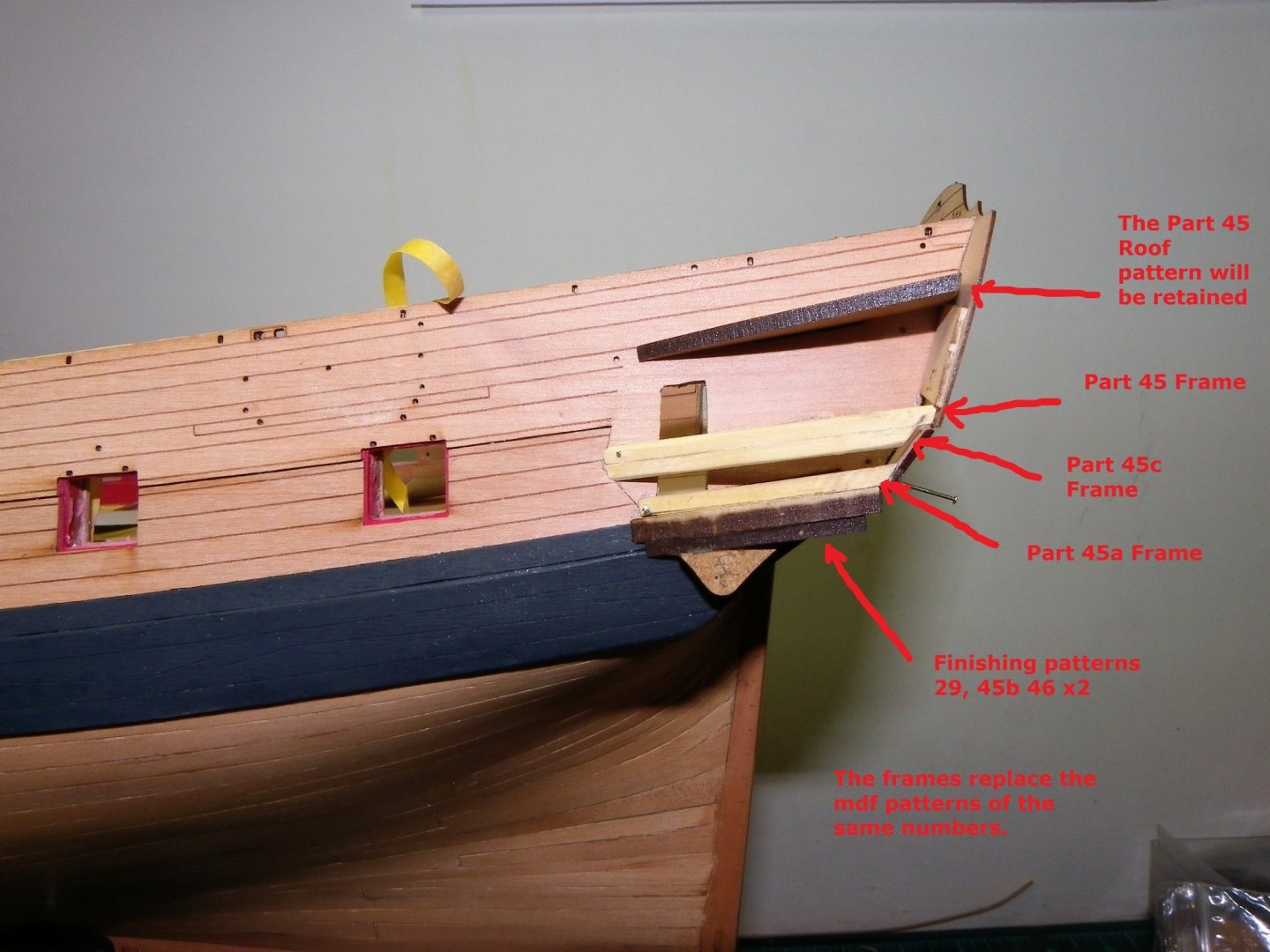
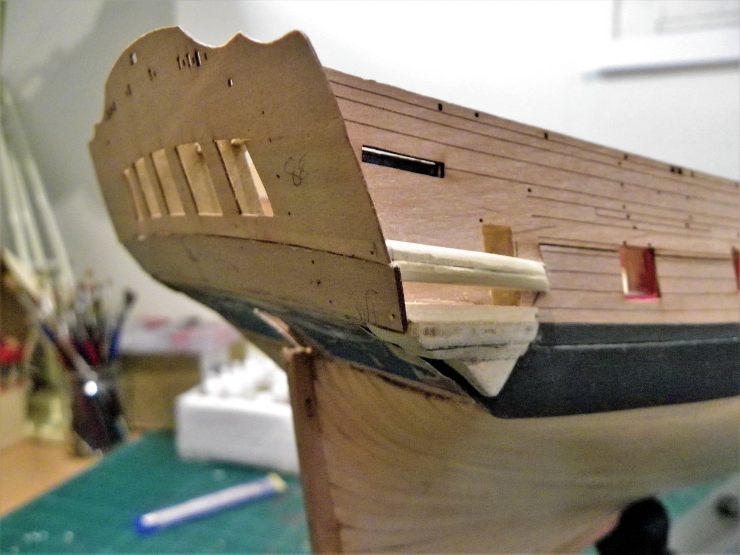
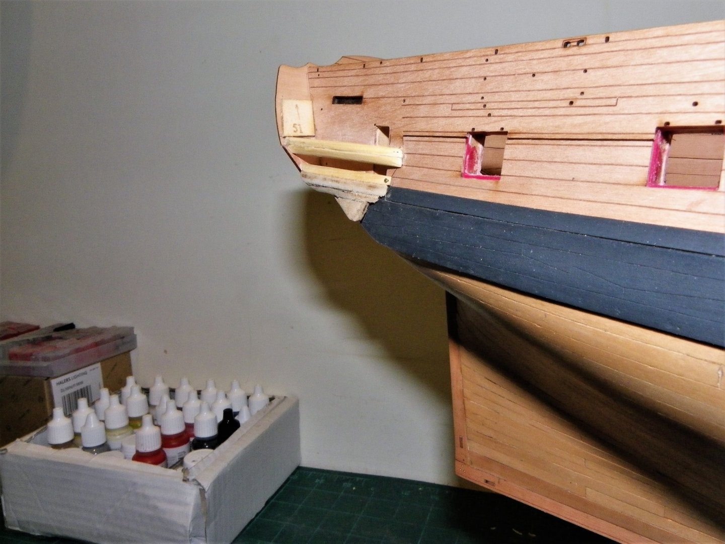
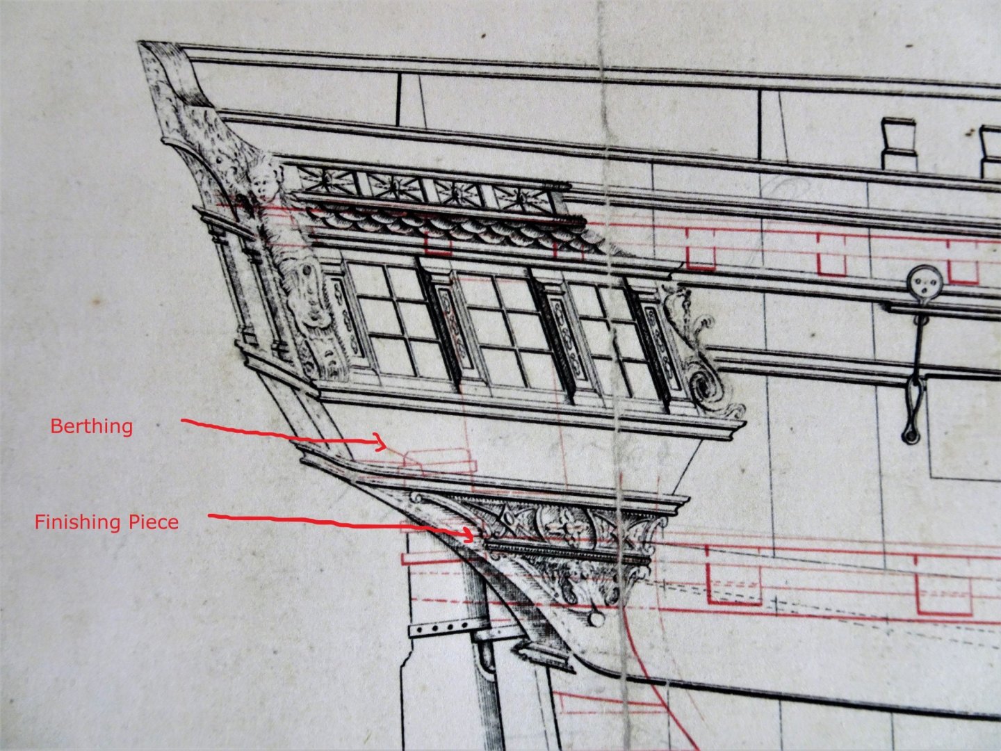
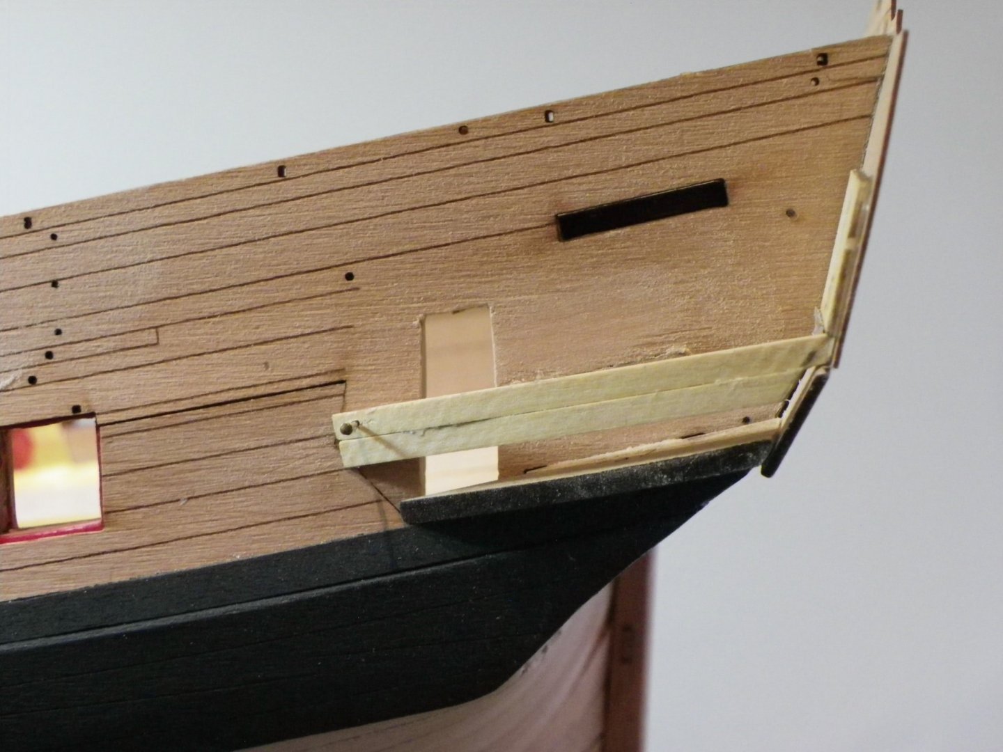
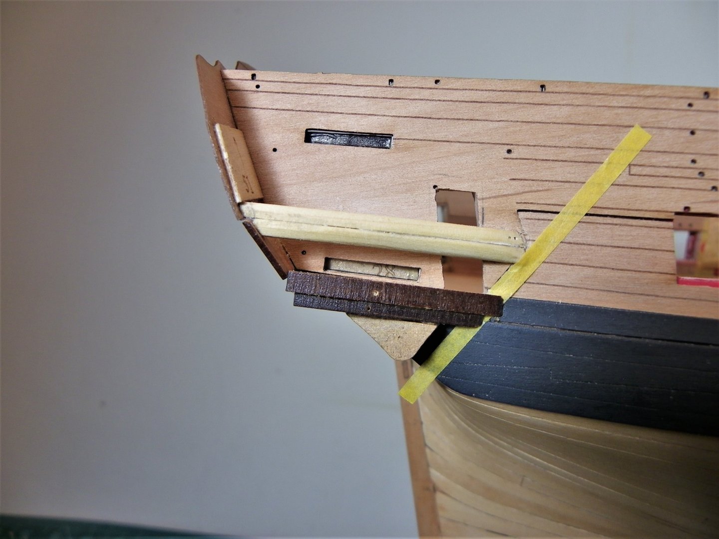
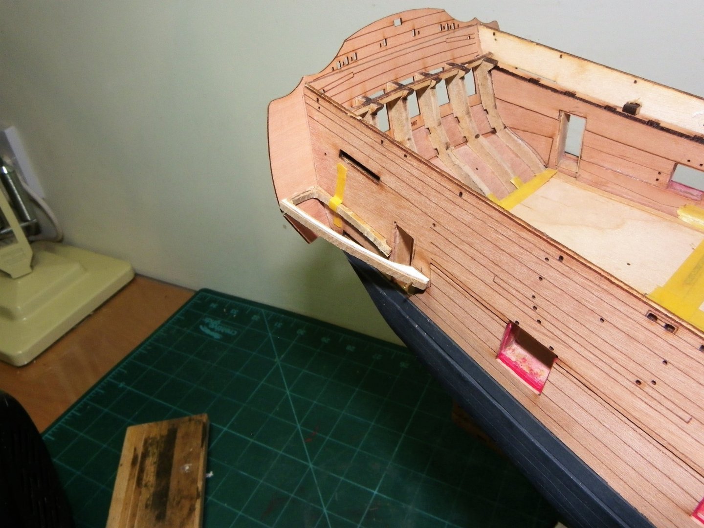
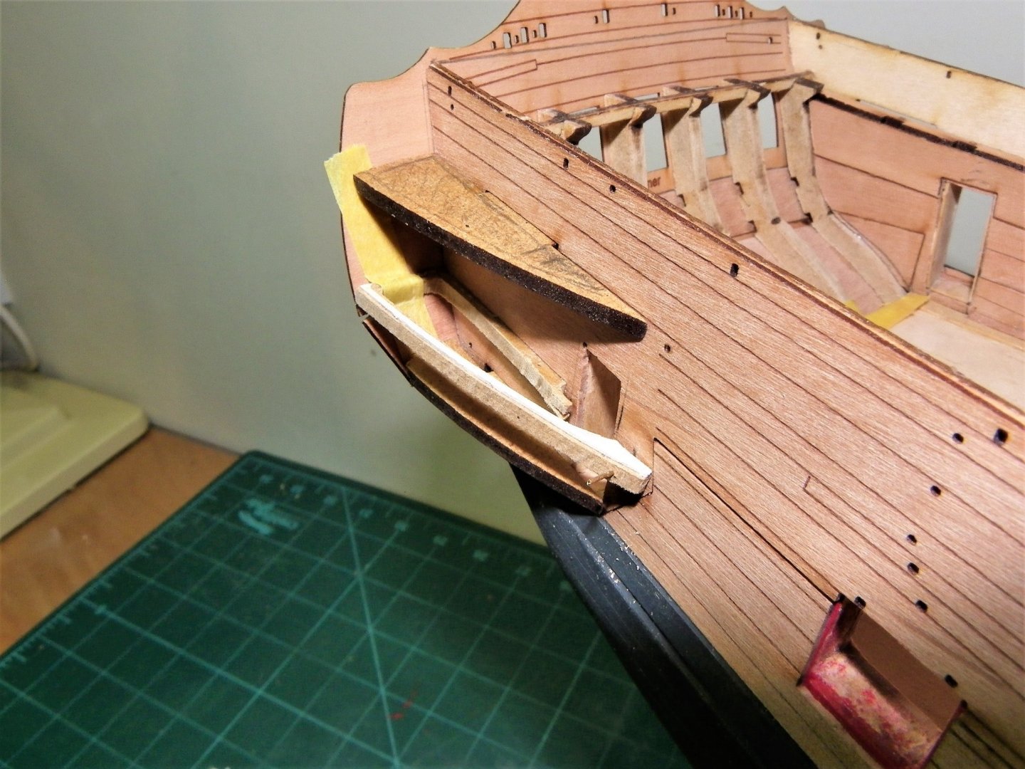
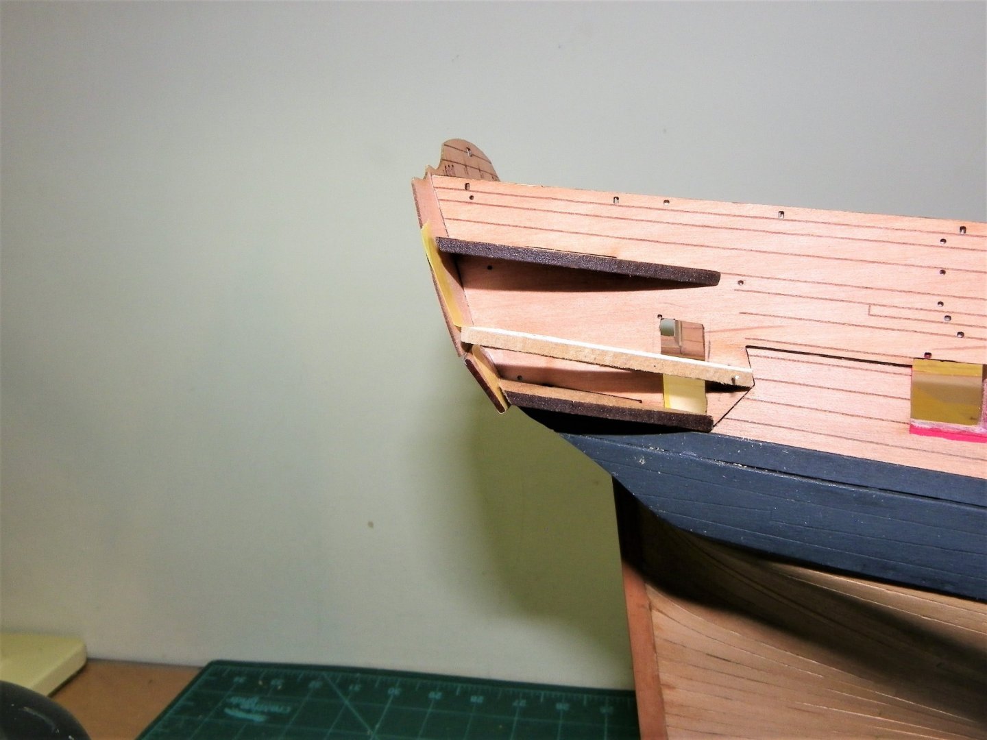
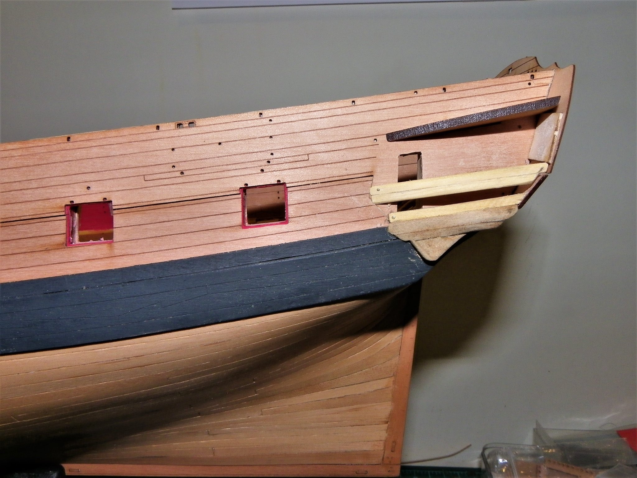
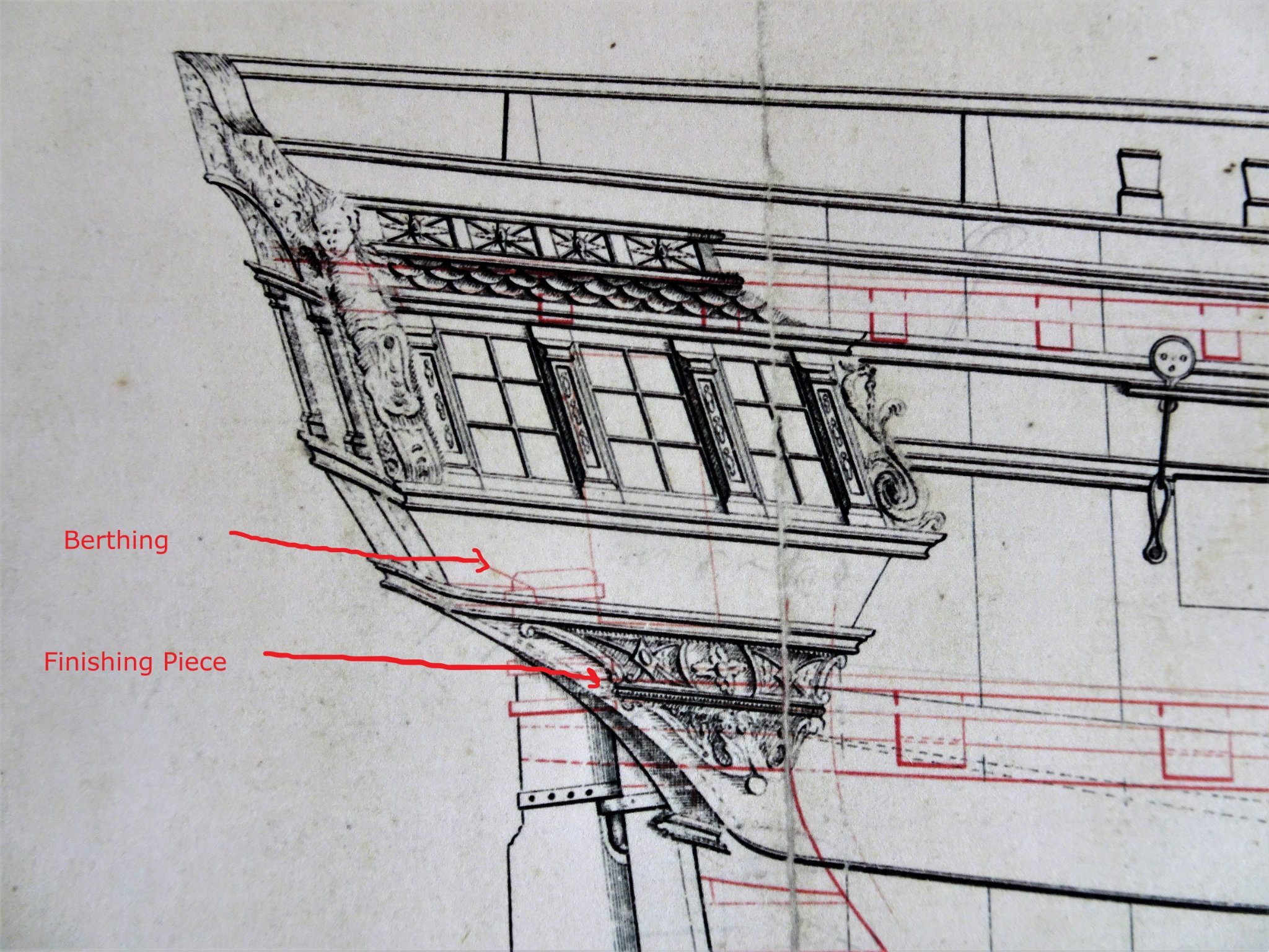
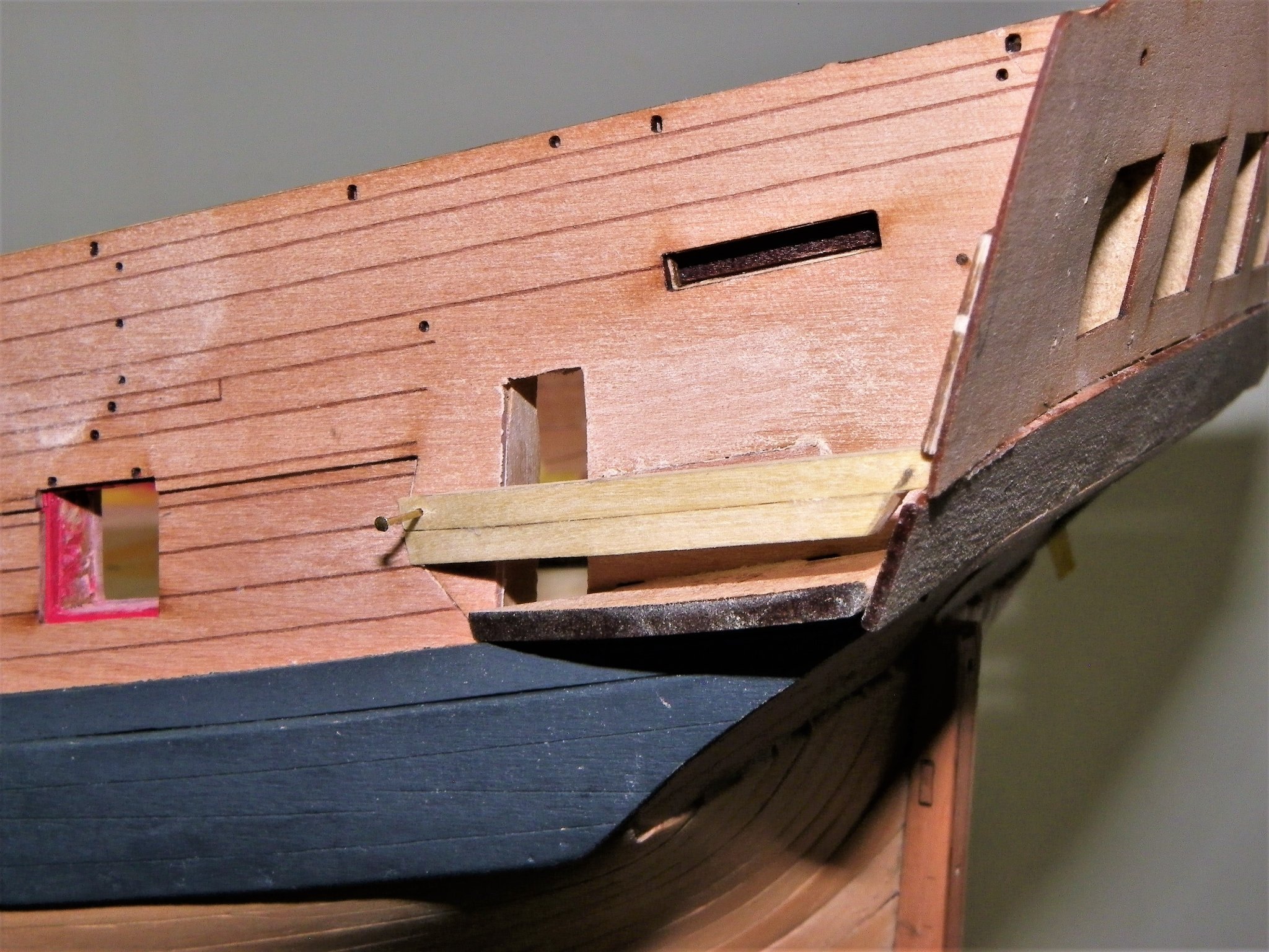
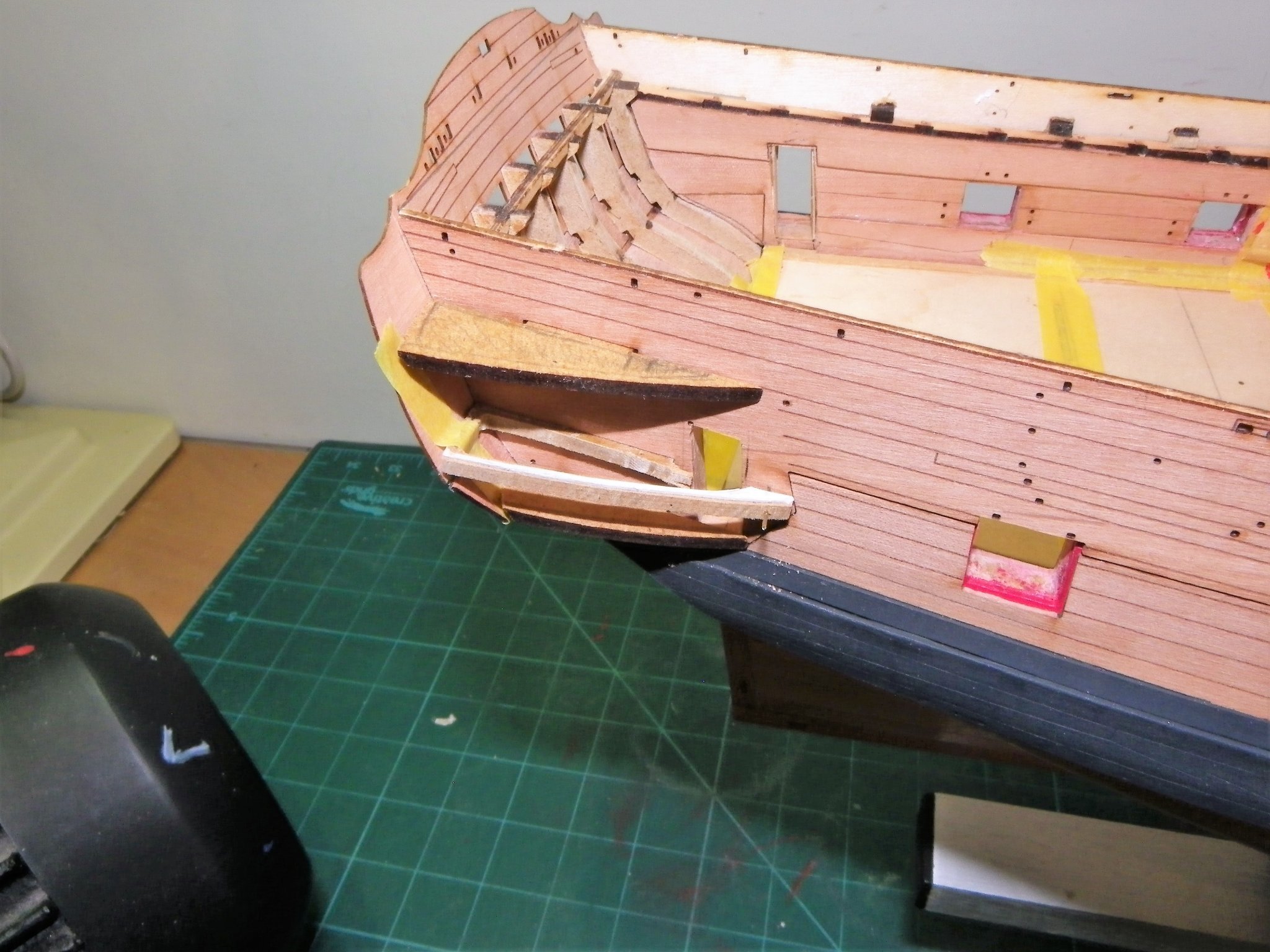
Post Forty-eight Gallery – Part Three At this point I have to attend to forming the Finishing piece. Not an easy task I think with multiple angles and subtle curves. No comforting pre-worked piece from Chris here unless you include the blocky patterns that make up the piece. On this detail from the original Admiralty plans the finishing piece sits just forward of the wale end with the forward edge following the angle line of the Berthing. 1586 Gallery detail from the beautifully drawn plans by Chris Watton. 1601 Part 29 which is the top of the finishing piece is effectively the floor of the gallery so a frame is required to sit atop this to replace part 45a as the bottom fixing point for the Berthing pattern. Confused yet? I know I am.🤔 A Boxwood frame is made to replace part 45a. 1591a The frame is pinned and glued into place. The block Finishing piece is held in place tight against the part 45a frame to ensure a good fit. Shaping of the Finishing piece can now begin A bit tricky deciding where to start with the shaping, and how to hold it during shaping. As it happens I didn’t find it too difficult on either count. The blurb indicates leaving the back edge of the piece untapered, sanding the forward part to a fine edge. The back edge needs to be bevelled downwards to follow the aft edge concave curve of the wale. I start by sanding the back edge of the piece to match the aft curve of the wale. Fortunately the mdf is soft so is easy to form. The biggest danger is getting too enthusiastic and take too much off or damage the shape. Soft hands, small strokes, and constant fit checks are the order of the day. 1619(2) 1608(2) Shaping in progress. This is one of those tasks that is difficult to describe, but hopefully as you get into it you start to see the shape emerging and get an appreciation of where to go. 1634 1631 1627 The Finishing pieces are glued to the hull and frame 45a. The final finishing of these pieces will be done once the Berthing pattern is in place. A seat of ease will now be added to the Portside gallery. B.E. 06/12/21

.thumb.JPG.5f37c0063353d20990fe3eedac208626.JPG)
.thumb.JPG.c3ec717e5294bd00f520577a94e83693.JPG)

- 857 replies
-
- 19
-
-
- Sphinx
- Vanguard Models
- (and 1 more)
-
Intriguing, a two masted Sloop, pre 1750 by the double wales, 12 guns, I'd take a punt at Speedwell. B.E.
- 1,784 replies
-
- 5
-
-
- winchelsea
- Syren Ship Model Company
- (and 1 more)
-
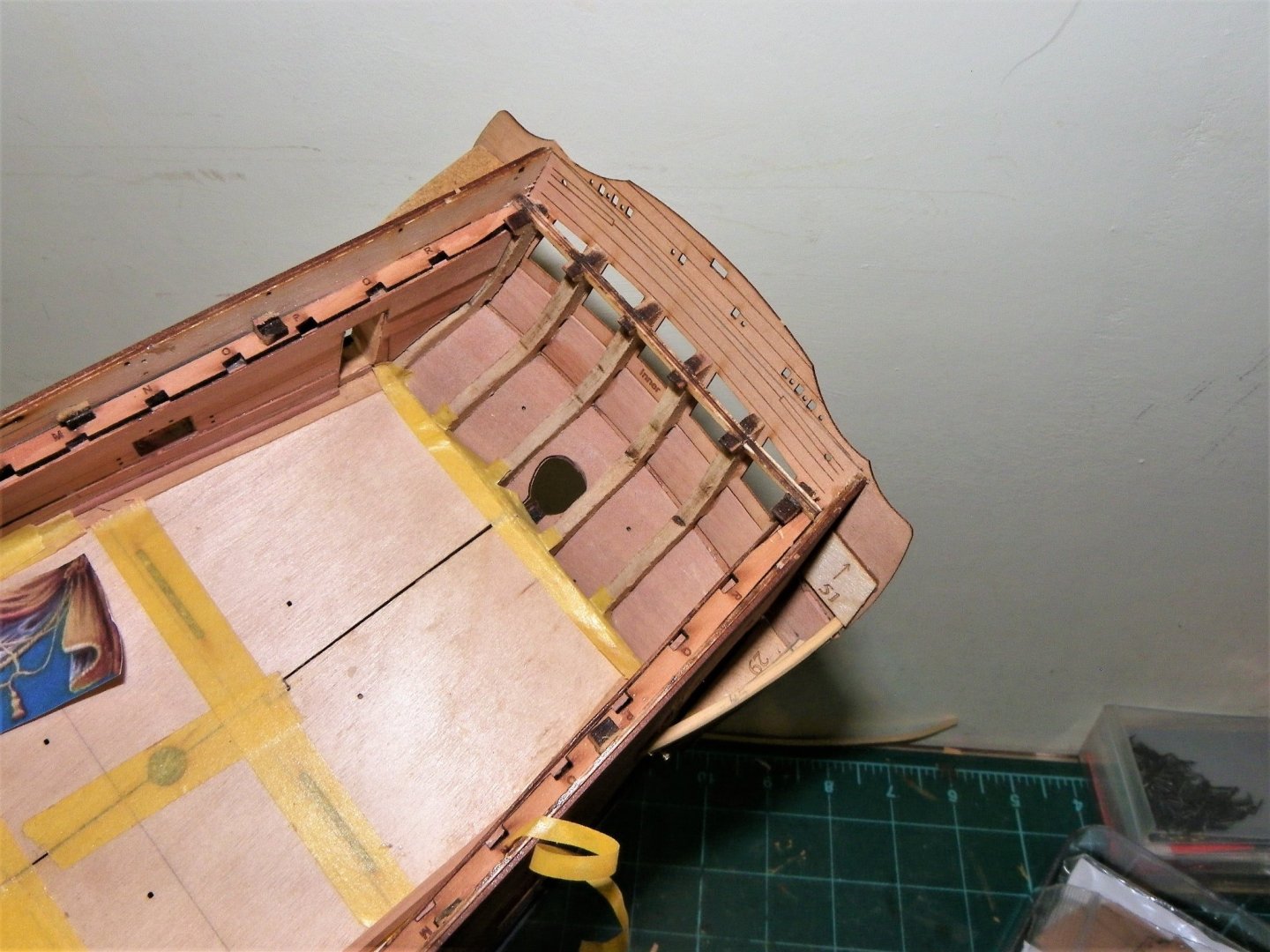
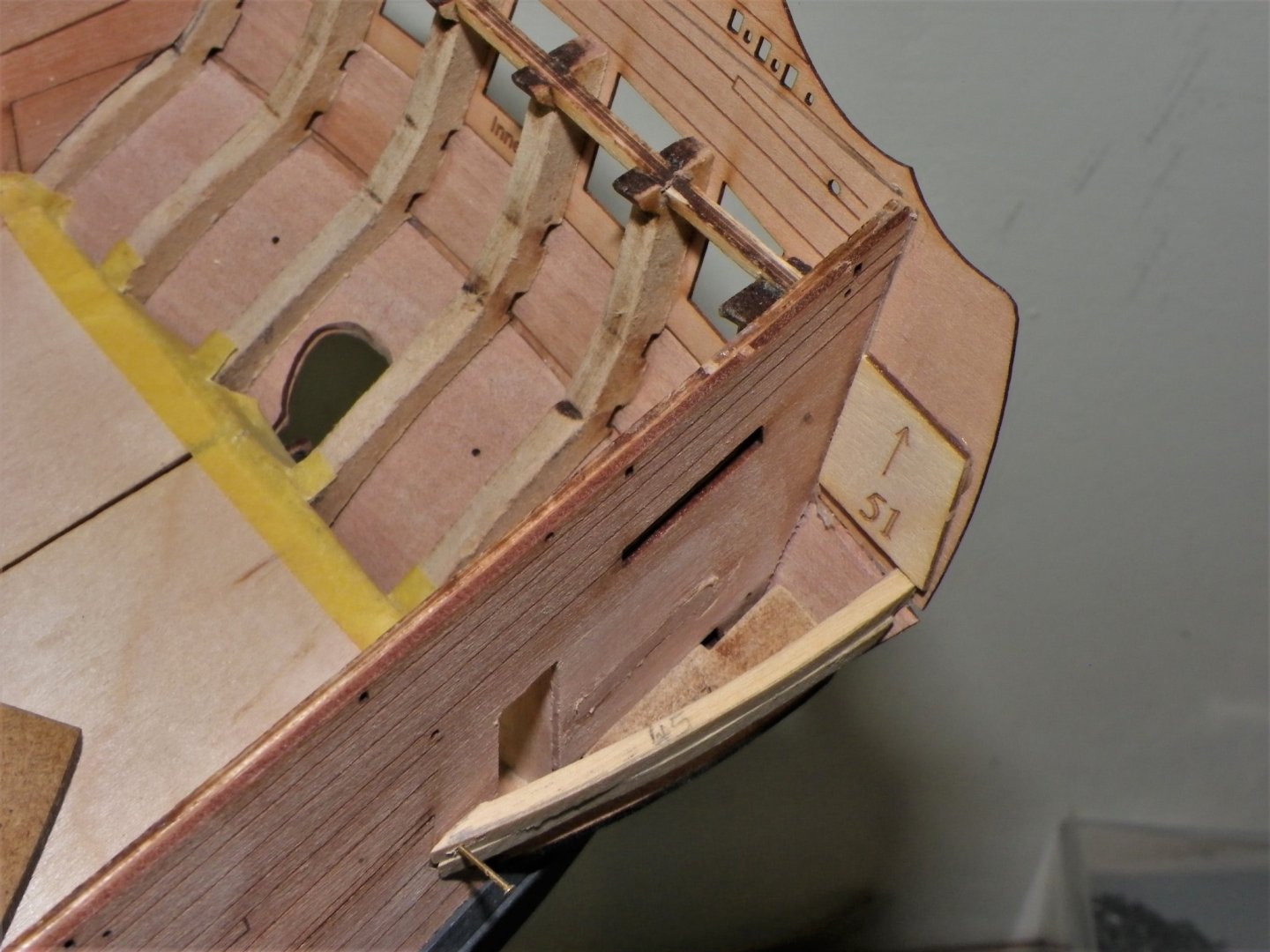
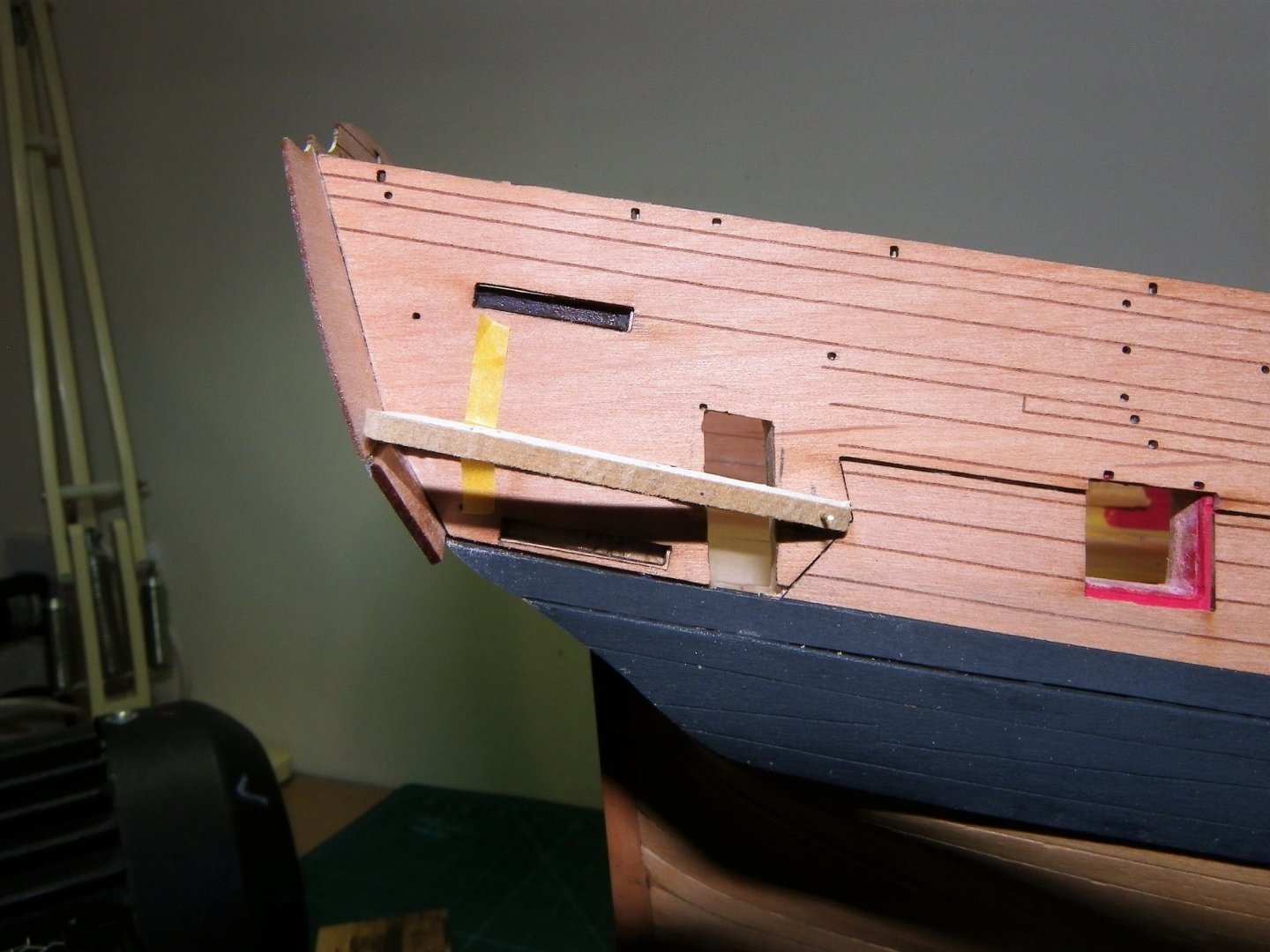
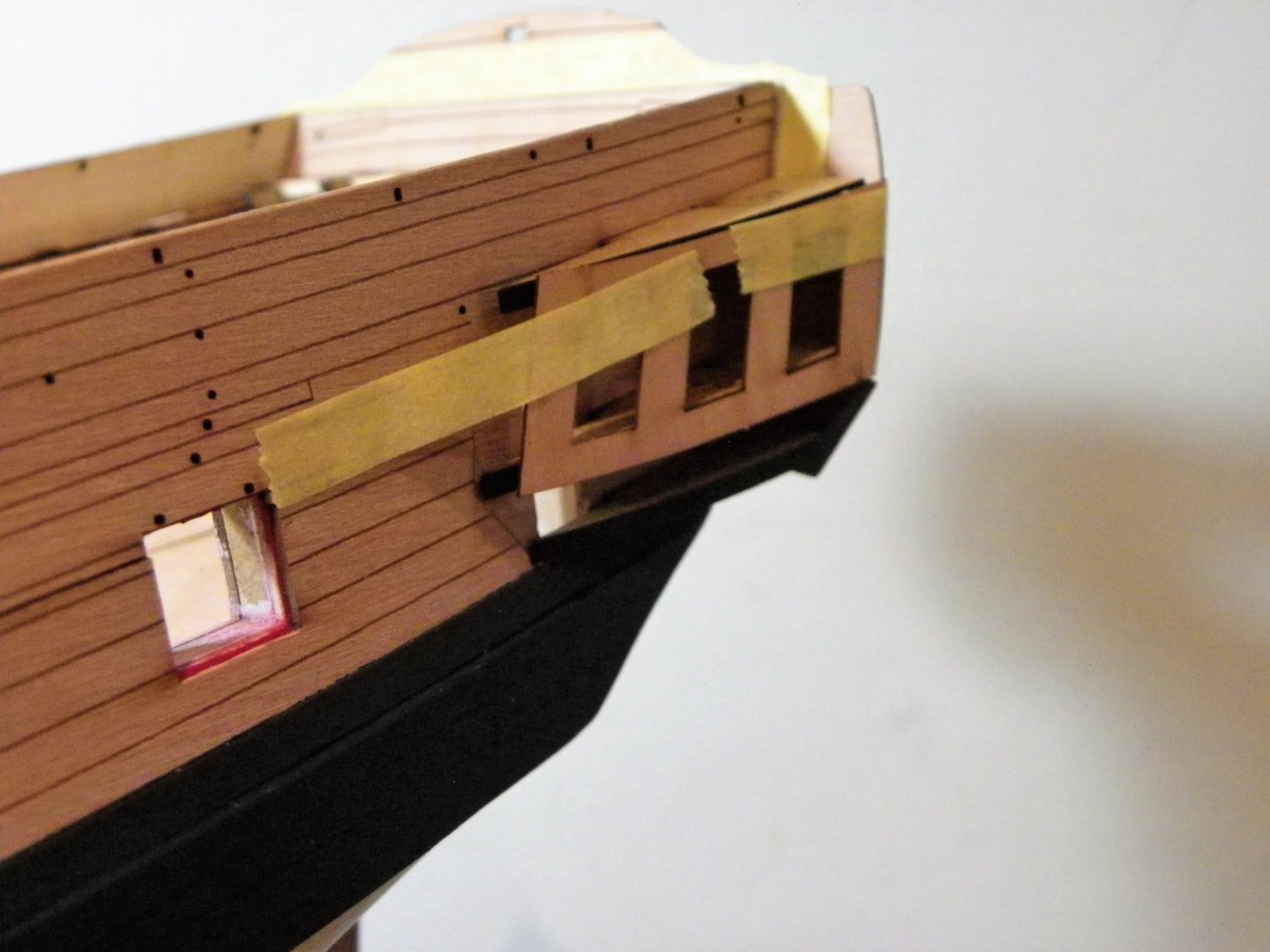
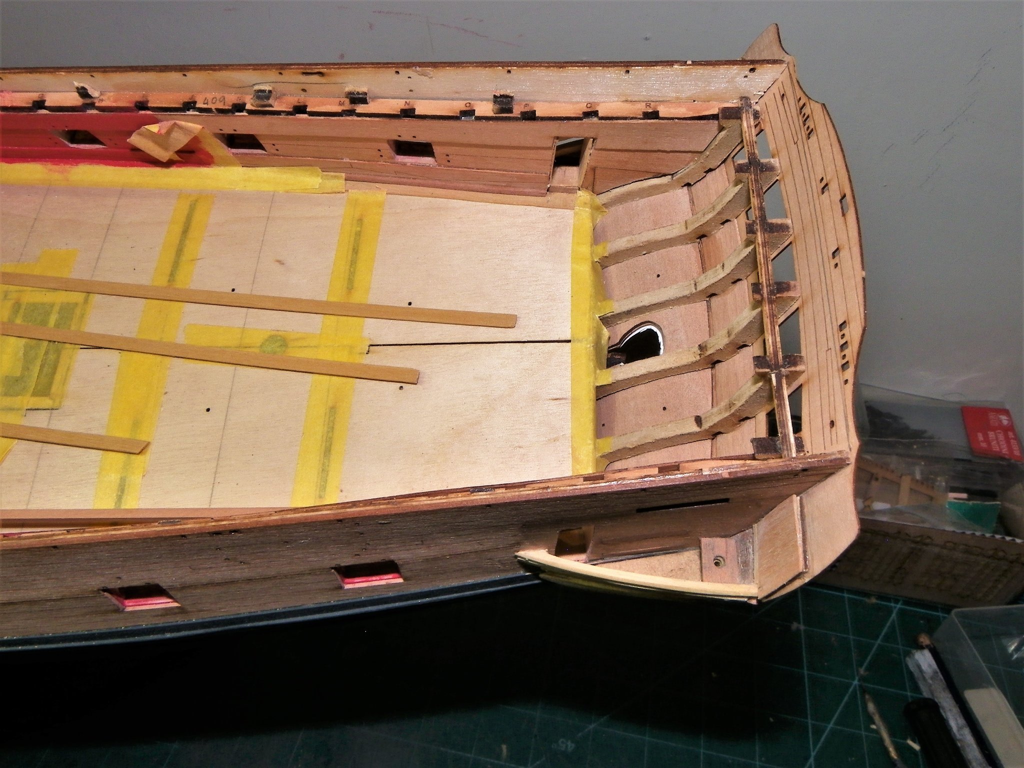
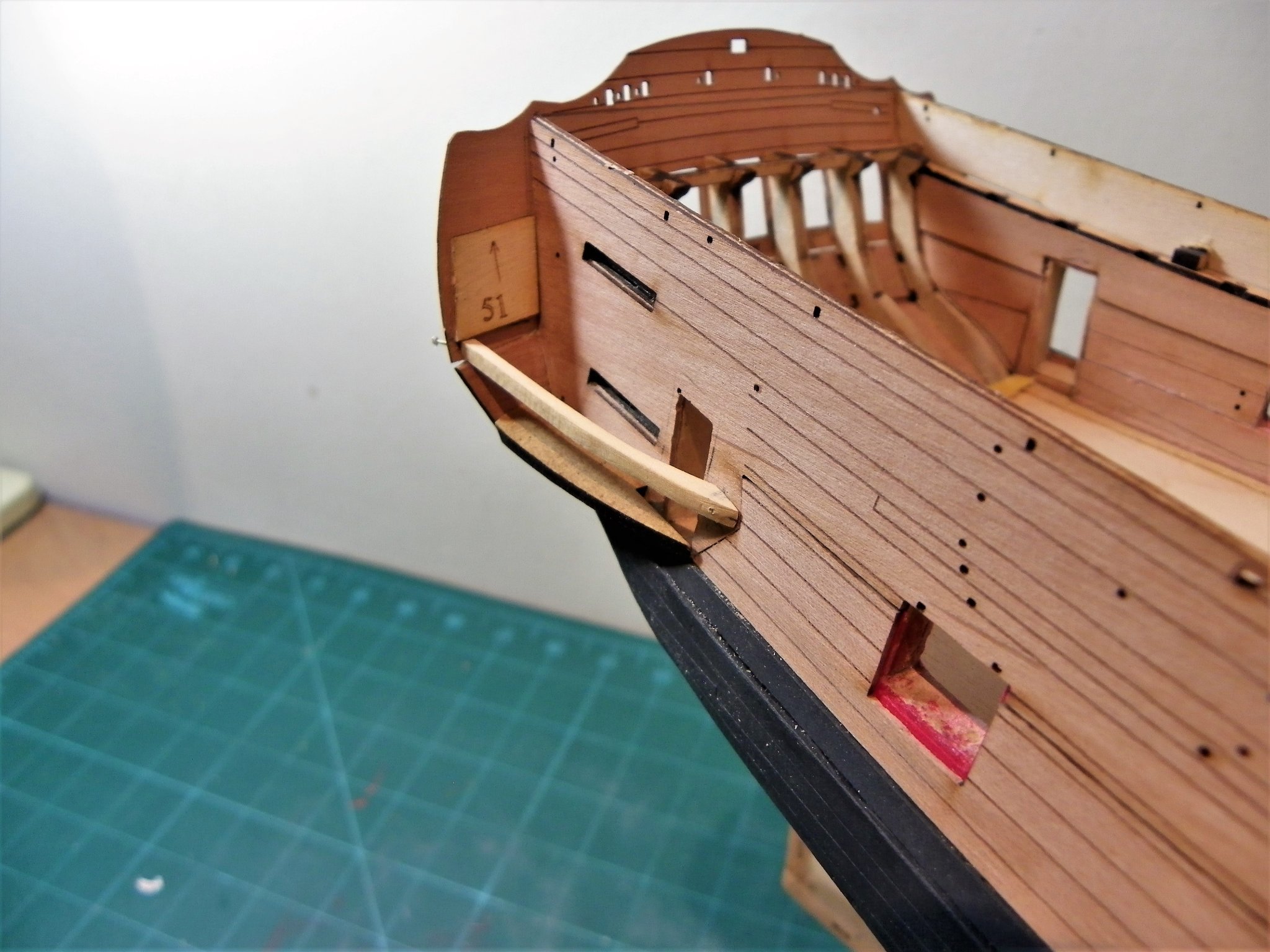
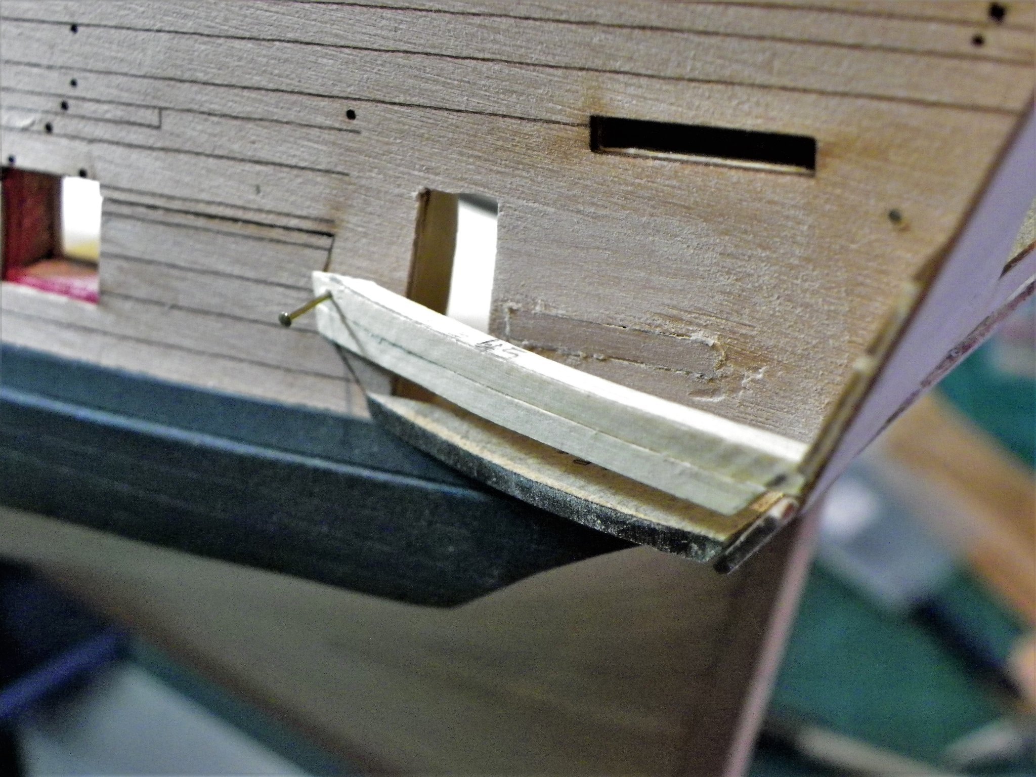
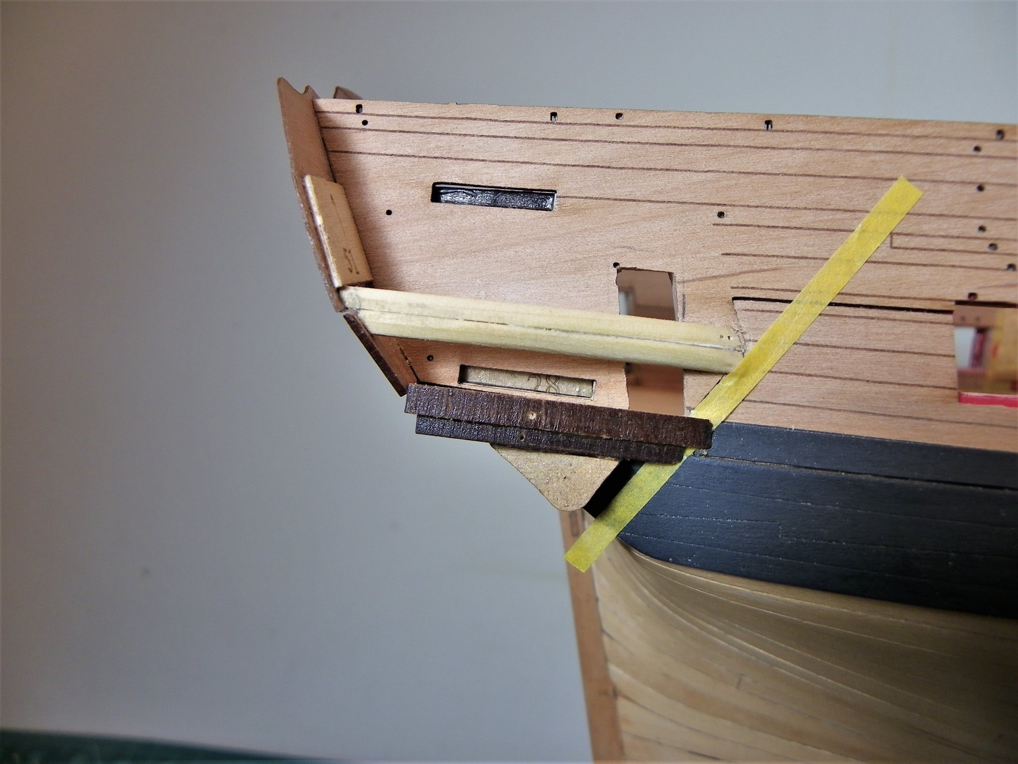
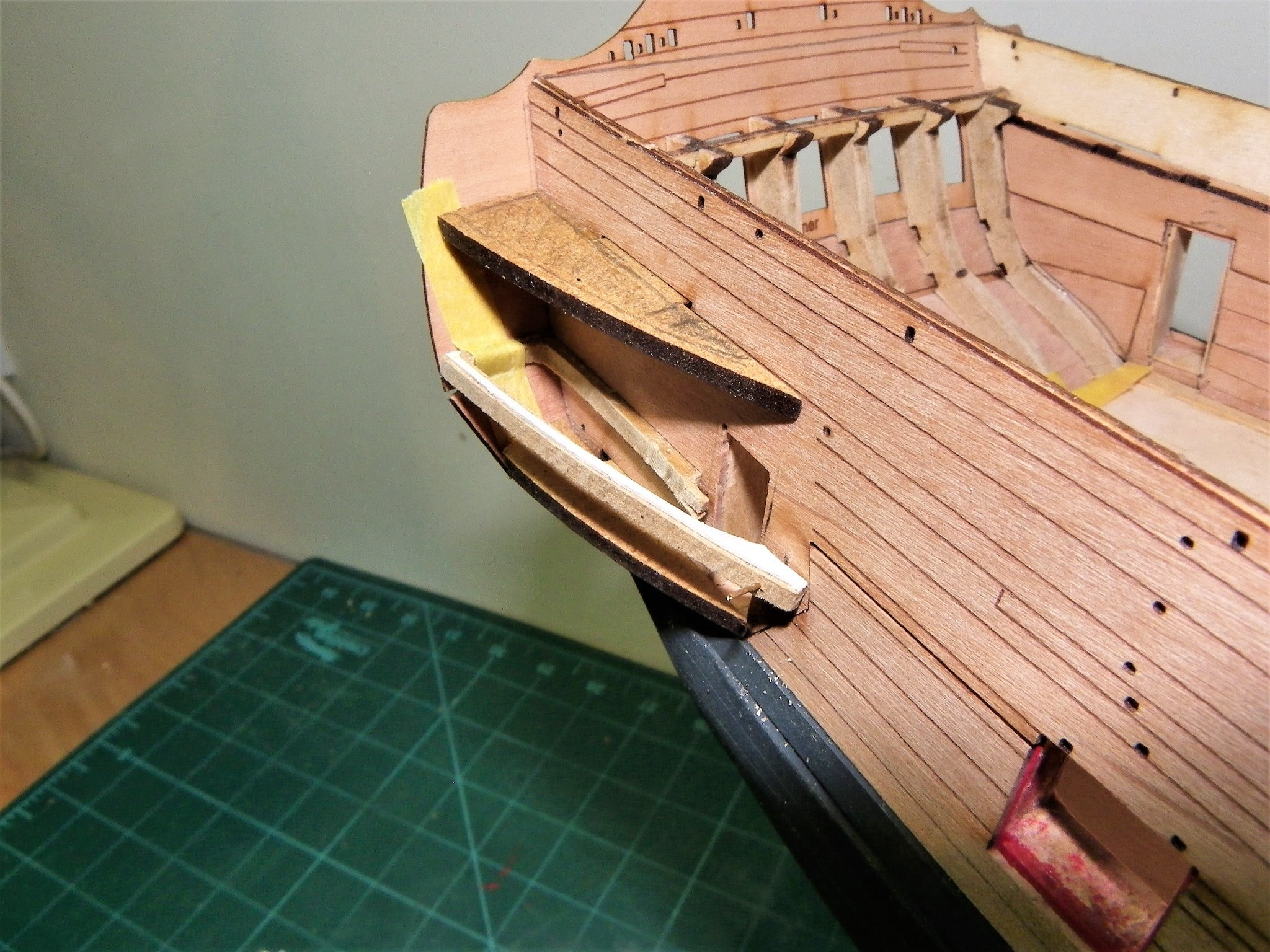
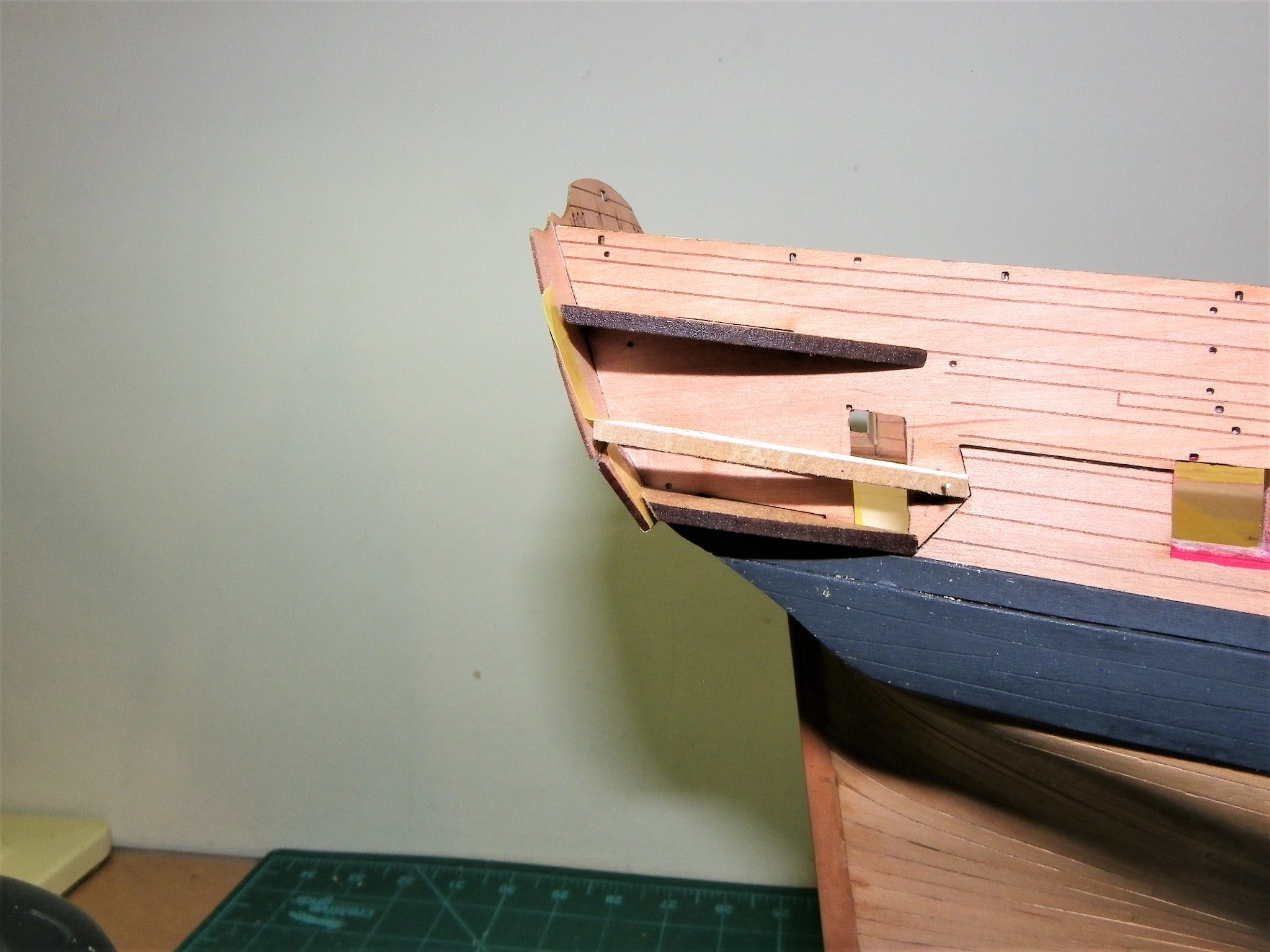
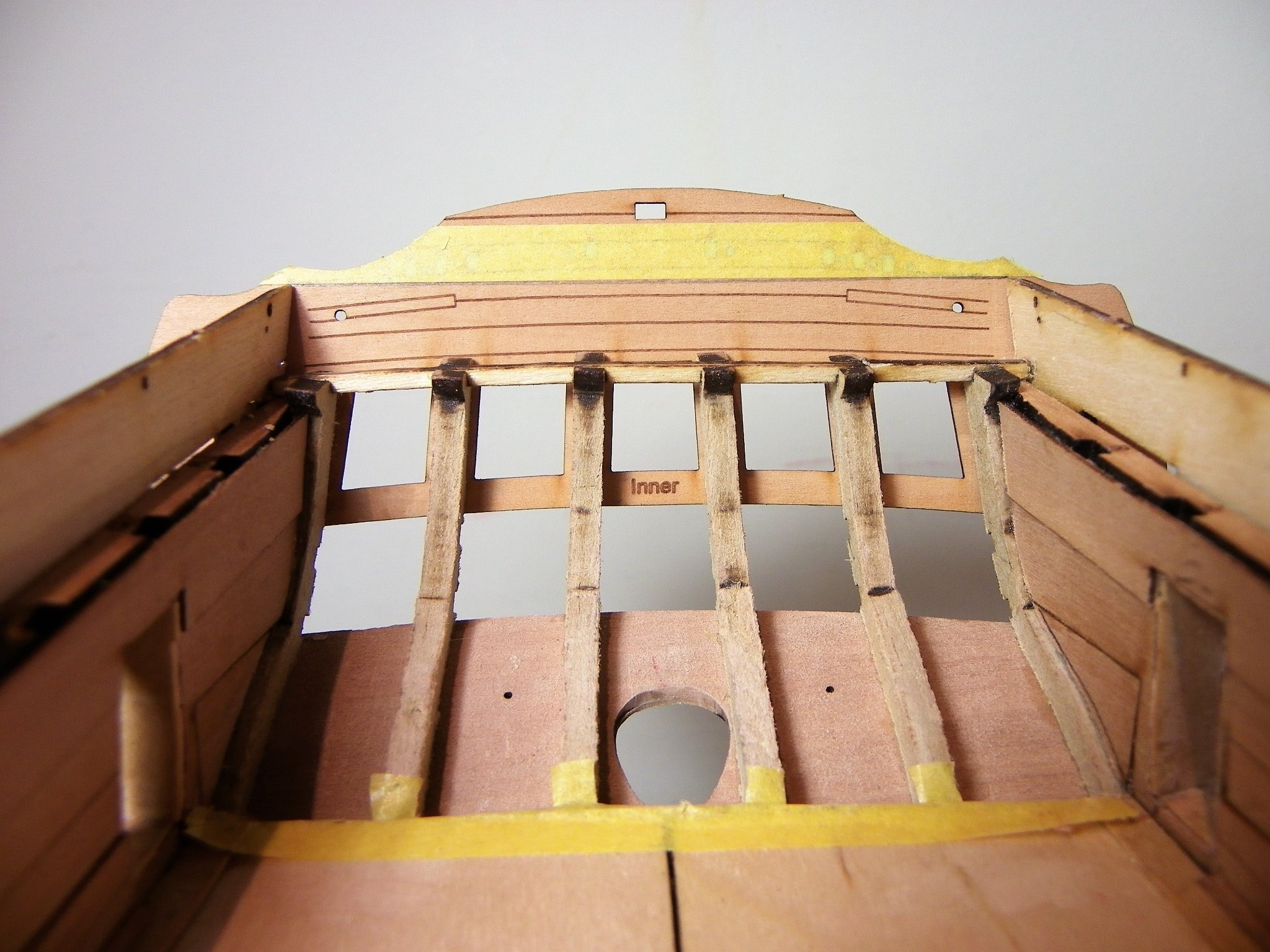
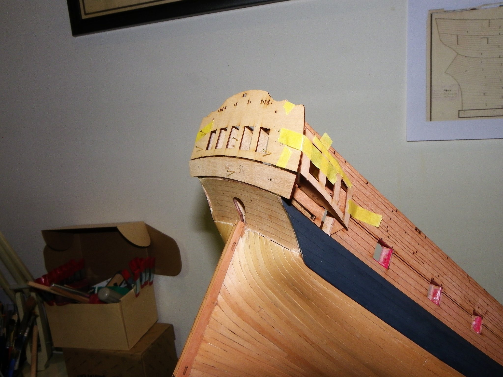
Post Forty-seven Gallery -Part Two I have replaced the middle gallery pattern (Part45) with a replacement Boxwood Frame. 1528 The lower pattern (45a) and its lower slot sits too high to represent what would be the floor of the gallery so this too will need modification at some point. The problem is compounded by the later insertion of another filler piece (45c) between the middle and lower parts 45 and 45a which would block off the gallery opening below the window level. Parts 45c and 45a provide the formers against which the berthing pattern (159) is glued below the window pattern. I concluded the issue could be resolved by doubling the depth of the middle frame to incorporate what would be part 45c. A frame was cut to match Part 45c which was glued to Frame 45. 1561 The combination frames pinned into place. 1565 The part 45a as shown here will not be fitted. 1573 Before fitting, the frames will require bevelling to suit the fit of the Gallery window pattern and Berthing pattern. 1570 To create a gallery in this style effectively means working from middle/bottom up rather than middle/top down as per the kit instructions. Fitting a seat of ease is required to be done before I fit the gallery window pieces and gallery top, but after the finishing piece is installed, as this will provide the floor. Any painting/varnishing of the gallery interior will also need to be done at this point. The finishing piece comprises four parts (29,45b,46) 1580 To assemble the finishing piece I used double sided tape to secure part 29 to the hull, it effectively runs along the top of the Black strake below part 45a the slot for which can be seen. The other parts were glued to part 29 insitu on the hull. The lowest part of the finishing piece follows the angle as indicated by the yellow tape. 1558(2) Finishing piece assembly, Starboard side. Note the angle of the two lower pieces(46) of this assembly. Shaping and fitting these will be the next task. B.E. 04/12/21

.thumb.JPG.789fa7c492e47eed852f815159e2181d.JPG)


- 857 replies
-
- 23
-
-
- Sphinx
- Vanguard Models
- (and 1 more)
-
Thanks Chuck, a case of not seeing the wood for trees, and I have been looking closely at your Winnie set-up as well. I'm glad you looked in.👍 B.E.
- 857 replies
-
- 4
-
-
- Sphinx
- Vanguard Models
- (and 1 more)
-
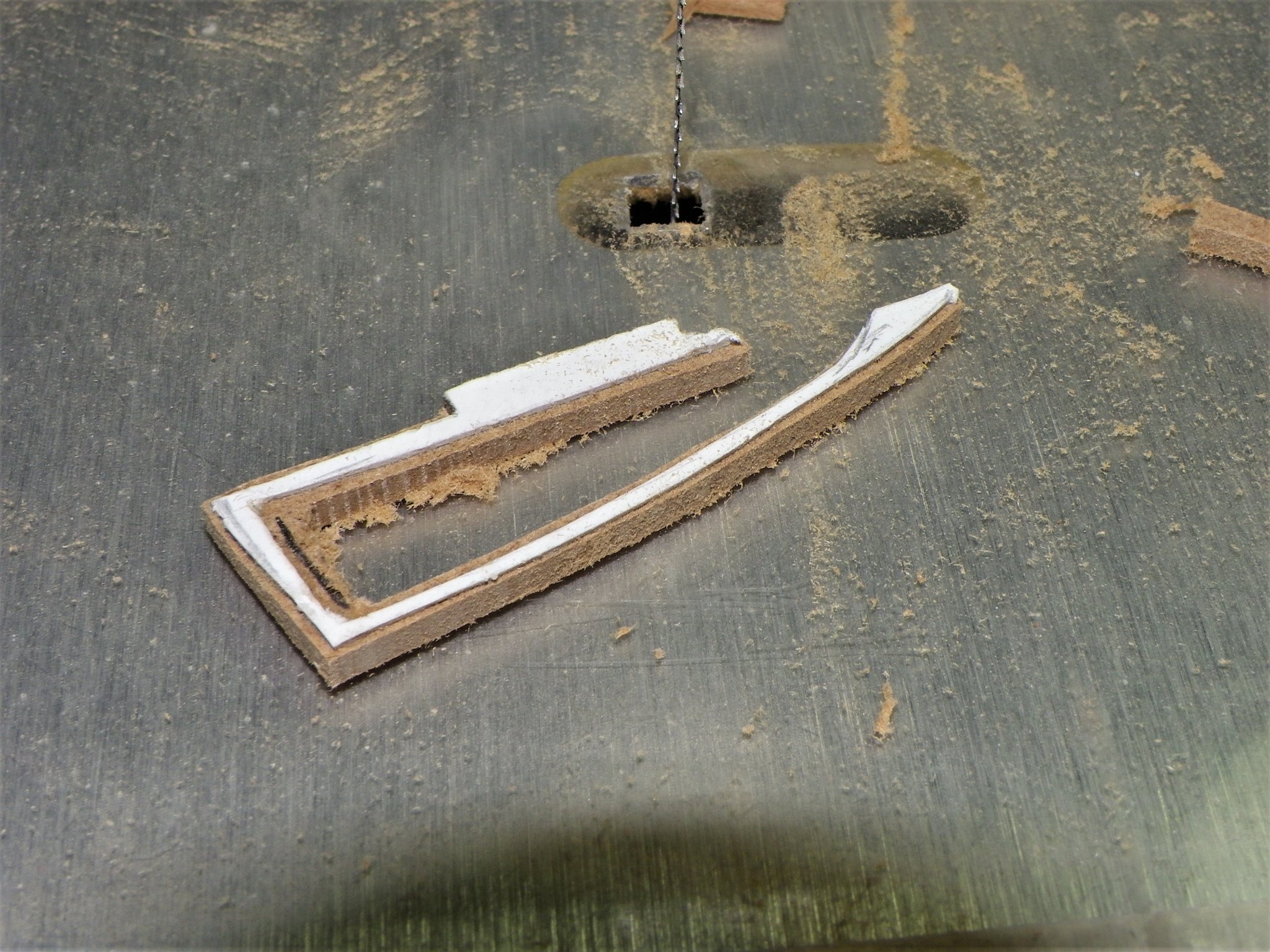
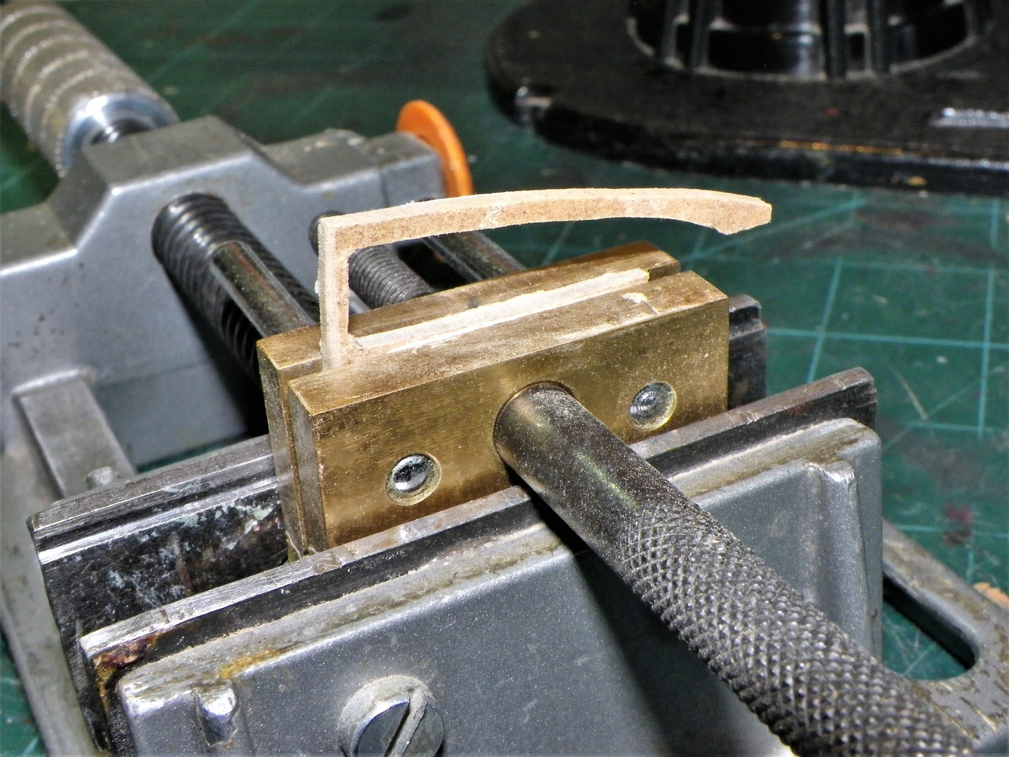
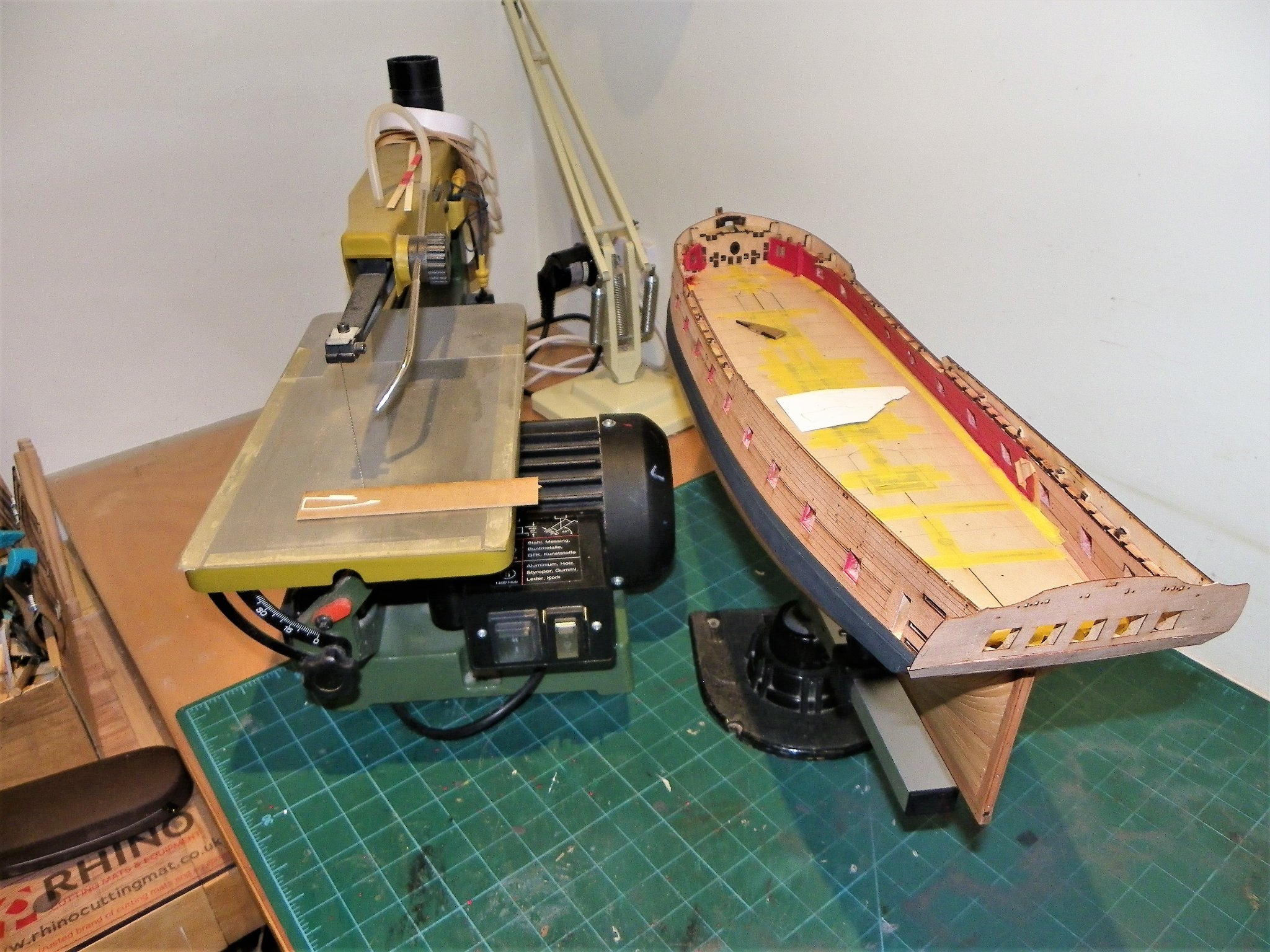
Thank you Ron, I do have a suitable 1:64 scale figure in mind for the role, a laser cut substitute part 45 would have been useful tho'.🙂 Post Forty-six Modifying the Gallery Time to clear the deck and get the scroll saw into position. 1488 The first trial to see how the mdf holds up. 1491 So far so good, the mdf has withstood the scroll blade without splitting. 1494 Final finishing is done gently by hand with sanding sticks. 1502 A trial fit. 1503 The forward end is drilled and pinned. 1506 Adding the other patterns which thankfully won’t need replacing. 1510 The line looks good to my eye. 1511 I think the modification is doable so I will try one cut from Boxwood sheet. On any final piece, once it is in place the back and inner sides would be fined down further. Back to the scroll saw B.E. 02/12/21


- 857 replies
-
- 16
-
-
-
- Sphinx
- Vanguard Models
- (and 1 more)
-
Post Forty-five Fitting facia and counter I first glue the upper counter in position with the facia still temporarily pinned in place. The gap at the bottom is filled with a narrow Pear wood strip. 1482 With counters dealt with, the facia is removed and re-glued into place. It is a bit of a milestone having the facia in place, it transforms the model into an 18thc naval ship even in its basic form as at present. I now reach the the point of a major modification. It concerns the middle pattern (of three) that form the shape of the Quarter galleries. This one carries across what would be the gallery space and block the doorway. 1478 This is an initial template of the piece that would have to replace the solid part 45. I’ll have a play around and see what material works best, possibly Boxwood sheet will provide the makings. I will start with cutting an example out of mdf and see how I go. Although I may ultimately decide that the result is not worth the effort, I’ve nothing to waste but my own time, and a little material, and I rather like the idea of a little figure making use of the seat of ease. B.E. 01/12/21

- 857 replies
-
- 14
-
-
- Sphinx
- Vanguard Models
- (and 1 more)
-
You could always ring them up (0)1905 776 073 and ask. Personally I haven't used Jotika/Caldercraft for some years, just providing the link I have. ps I have just checked with Jotika they do have them in stock, but for some reason they haven't appeared on their online store. Cornwall Model Boats do have them, I've just checked.
- 126 replies
-
- 1
-
-
- le superbe
- heller
- (and 2 more)
-
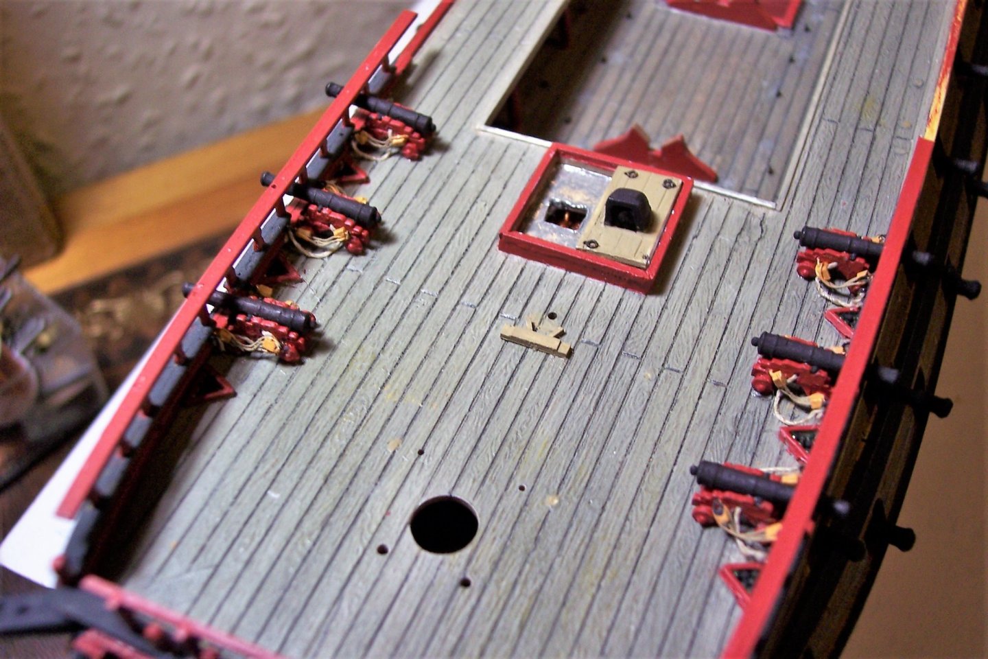
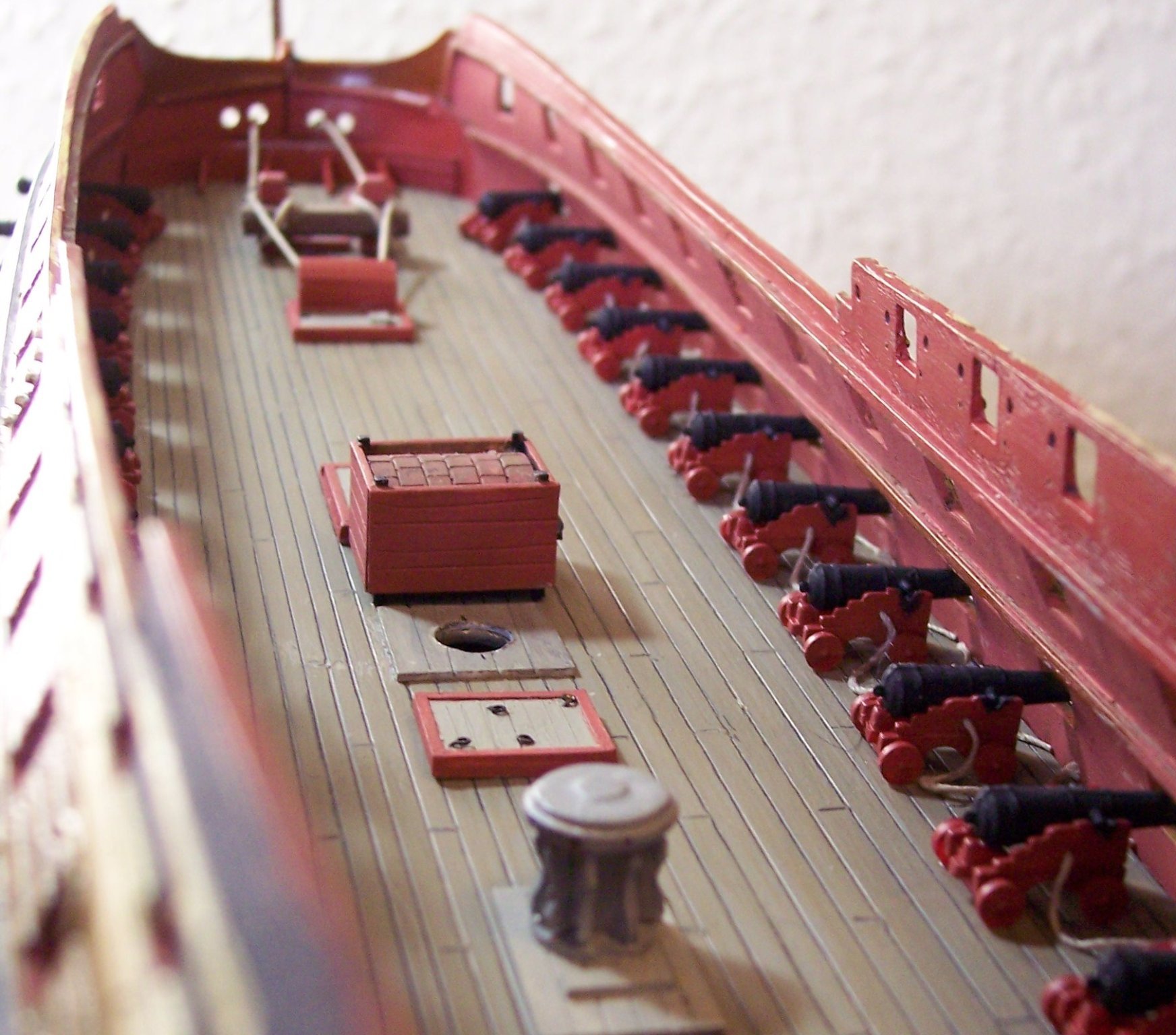
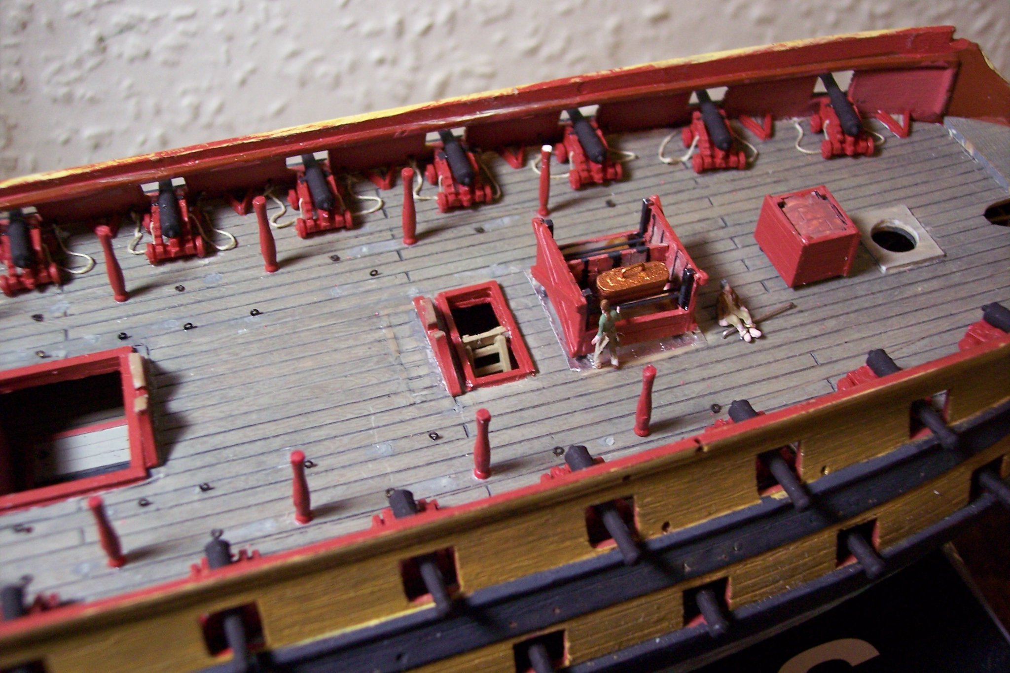
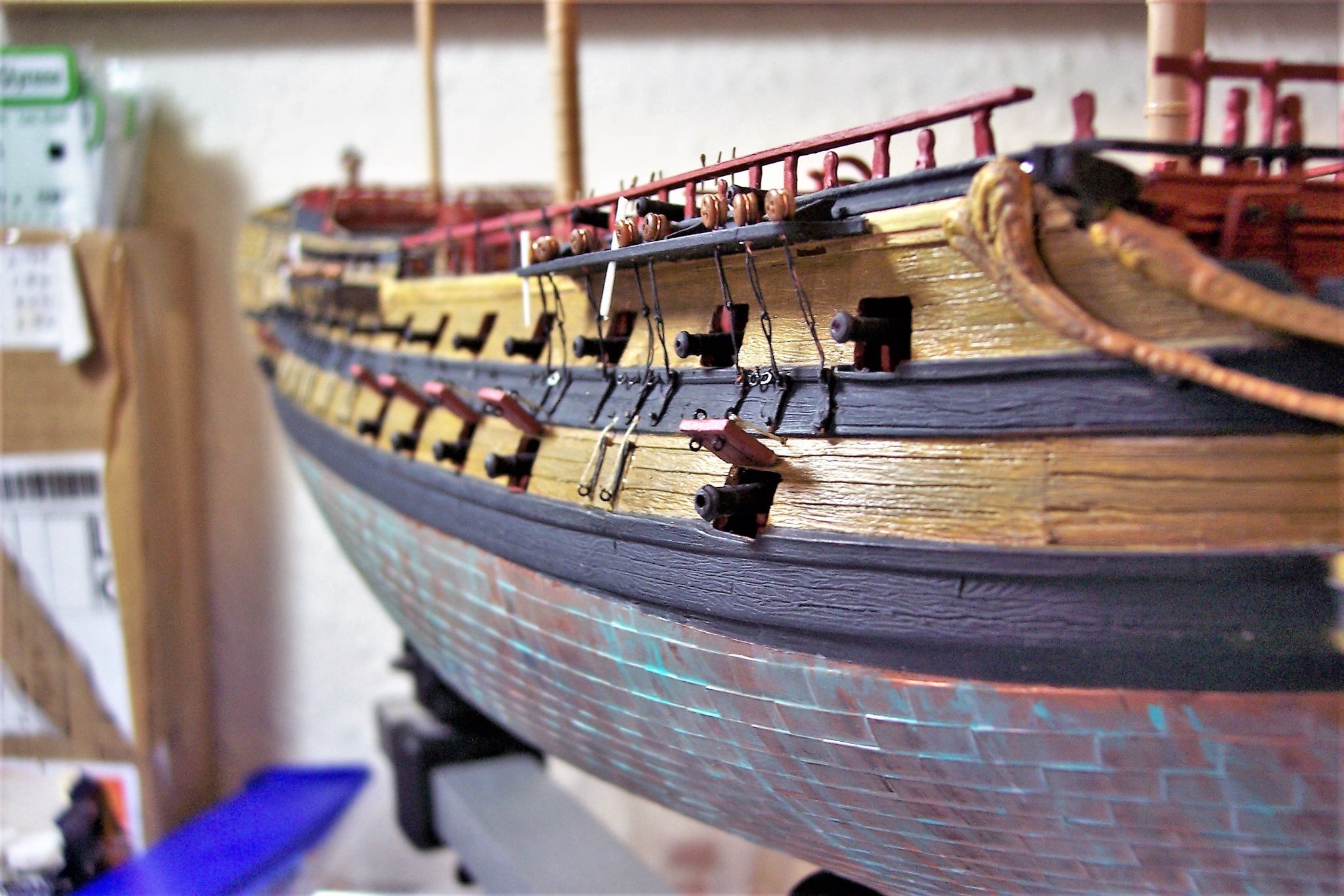
Hi Admiral Beez, I have had a look back thro’ my records, and I hope this info helps. All those rings for the tackles and port lid lanyards, and almost every other instance where an eyebolt or ring was required are 0.3mm Brass etched eyelets obtained from Jotika. Here’s the link JoTiKa Ltd. ~ Fittings, 0.3mm Brass Etched Eyelets. (jotika-ltd.com) As regards the port lids, this is what I wrote at the time. The port lids provided by Heller are little projects on their own, each lid requiring nine separate operations before they are ready for fitting; at least there are only twenty-eight of ‘em. For some strange reason Heller have moulded the grain running the wrong way, vertical instead of horizontal. The hinges are adequately formed but will require the addition of lanyard rings, these rings should be inside the hinge straps, but I have attached them to the straps as I think they look better. Horizontal boards had to be scribed on the outer face, and vertical (lining) boards on the inner. The usual sink holes on the inner sides of the lids had to be filled, before scribing, painting the usual red ochre, and marking with the diamond head nail patterns. How to fit the ports is something of a puzzle; the lugs on the top of the lids are offset from the back so that the lid should fit flush to hull when closed. Unfortunately, they are too thick to allow the lid to sit flush without thinning down. For open ports there is no recess on the hull to take the ‘hinges’ and the Heller instructions give no clue as to fitment. I notice that looking at other Heller 74 builds on the net that many completed models do not have the lower port lids fitted, I wonder why. In any event each lid required individual tailoring to fit – chamfered edges and thinned down lugs. For the closed ports they were such tricky beggars to fit that all my fine painting of the lids and brackets came to naught as the paint mostly rubbed off whilst handling. In fitting the lids a line was temporarily secured to the rings to guard against the lids being lost inside the hull during the fitting operation – easily done. 0.1mm line was used for the lanyards which were threaded thro’ the previously prepared holes at Stage One, fished thro’ knotted and pulled taut. For the open ports a slightly different approach was required. 0.4mm holes were drilled in the top of the lid to take short lengths of telephone wire super-glued into place. The moulded lugs were removed. Corresponding holes just above the port openings were drilled to take the lid wires which once fitted into place can be gently positioned for angle once the lanyards have been fitted. Such was the good fit of wire into hull gluing was not necessary, but a lot of re-touching of the paint was required where the lids had been gripped by pliers and tweezers during the process. Were I to do the job again this is the sequence I would adopt. 1) Fill sink holes and scribe planking. 2) Drill holes for lanyard eyelets. These operations can be done whilst the lids are attached to the sprue. 3) Select and pare down lids to fit for closed ports. 4) Remove lugs from ports selected to be open. 5) Drill holes in top of open lids to take wire lengths to fit into hull. 6) Glue outside lanyard eyes into place on lids, (all lids) 7) Drill and fit inside lid eyelets on open port lids only. 😎 Paint the lids and straps. Port lids detail On the subject of Gun tackles For the smaller Foc’sle and Qtr deck guns I used 0.1mm ø line for the Breeching ropes, and for the larger lower deck guns 0.2mm ø line. I don't think I seized the breeching lines to the bulwarks , merely passed them thro' the rings where fitted, pinched them, and sealed with a spot of ca. These are very tiny things and the knot would be too big. Foc'sle gun detail This is what I wrote: Once installed the first job is to fasten the rings for the Upper deck waist cannon. The holes were drilled before assembly of the hull halves – impossible once the hull is assembled. There is not an option to omit any cannon as all the ports are open on this deck. The 0.3mm brass etched eyelets are just perfect for this job. For the six cannon beneath the Gang-boards in the waist I had fitted bulwark rings, and what passes for the breeching ropes on French cannon were attached to these. For the others Breeching ropes were attached and super-glued to the deck, as on the Gun-deck. Waist gun detail On the Lower deck I have represented the breeching ropes only, which are super-glued to the deck to provide additional security. Lower deck gun detail. Cheers, B.E.


- 126 replies
-
- 5
-
-
- le superbe
- heller
- (and 2 more)
-
Good to hear from you Michael, I hope things are good with you. Regards, Maurice
- 126 replies
-
- 1
-
-
- le superbe
- heller
- (and 2 more)
-
Nice detailing Ron, for me one of the most enjoyable parts of a build. B.E.
- 542 replies
-
- 2
-
-
- Sphinx
- Vanguard Models
- (and 3 more)
-
I have found that painting directly over Pear wood with Vallejo paints worked very well. I think James on his prototype build sprayed directly onto the bare wood, but applied wipe-on poly before brush painting the interior bulwarks. With a hardwood like Pear I don’t think it necessary to seal before painting, maybe varnish post painting to protect the surface. B.E.
- 505 replies
-
- 7
-
-
- vanguard models
- Sphinx
- (and 1 more)
-
A few questions there Admiral, I will have to dig out my old log record and see what I did. I will get back to you. B.E.
- 126 replies
-
- 1
-
-
- le superbe
- heller
- (and 2 more)
-
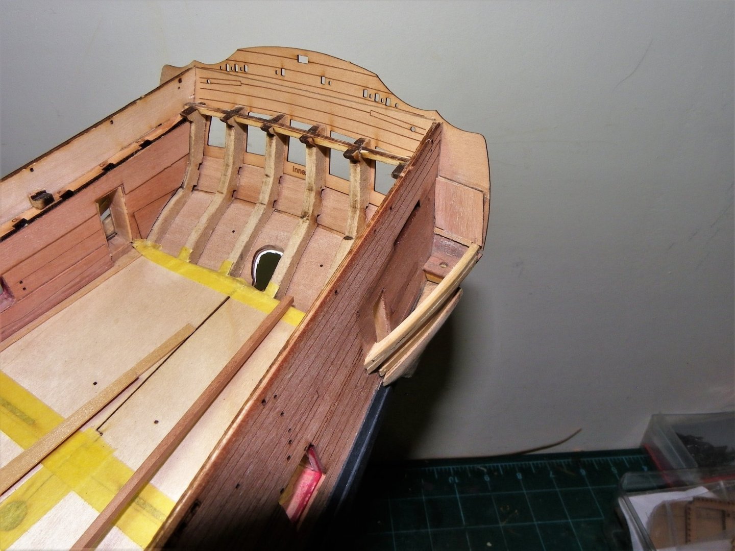
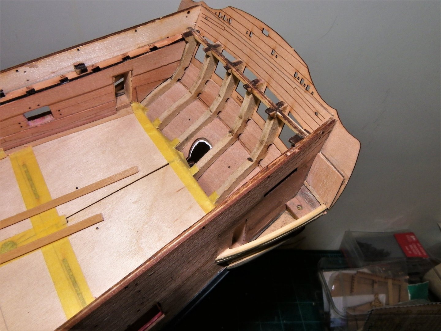
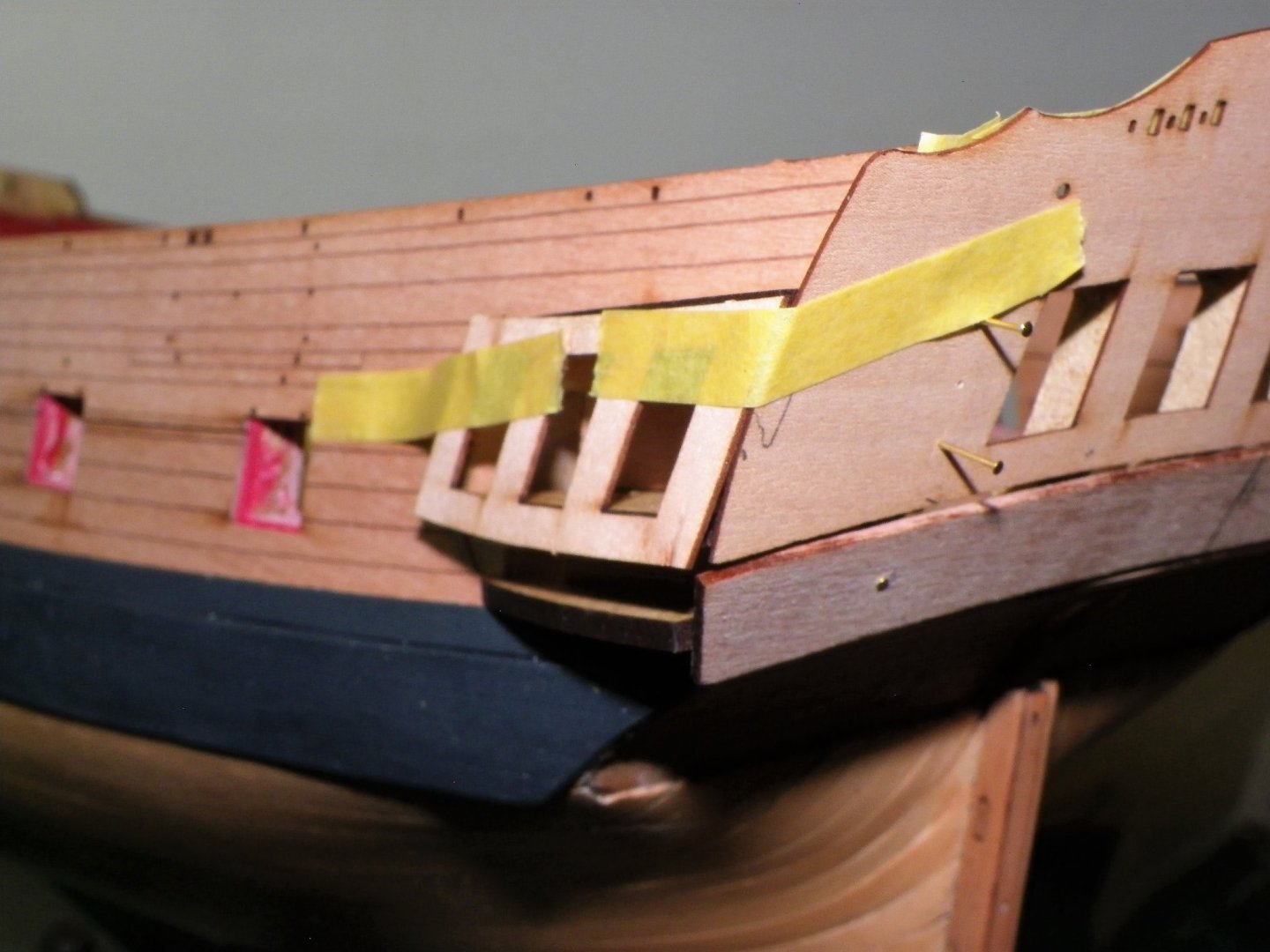
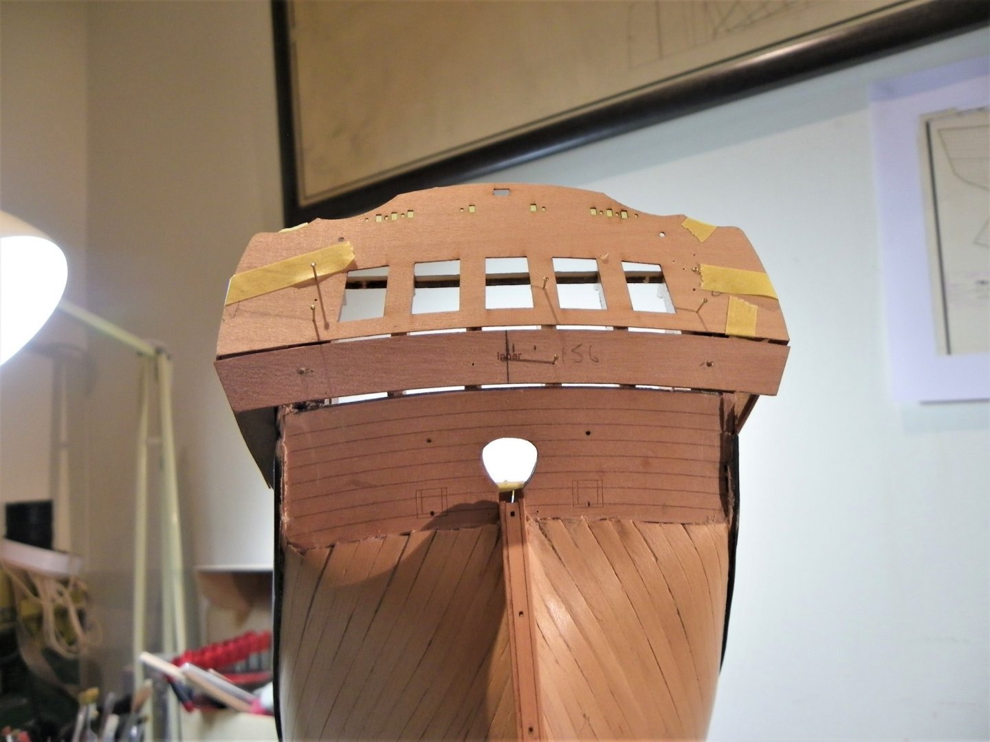
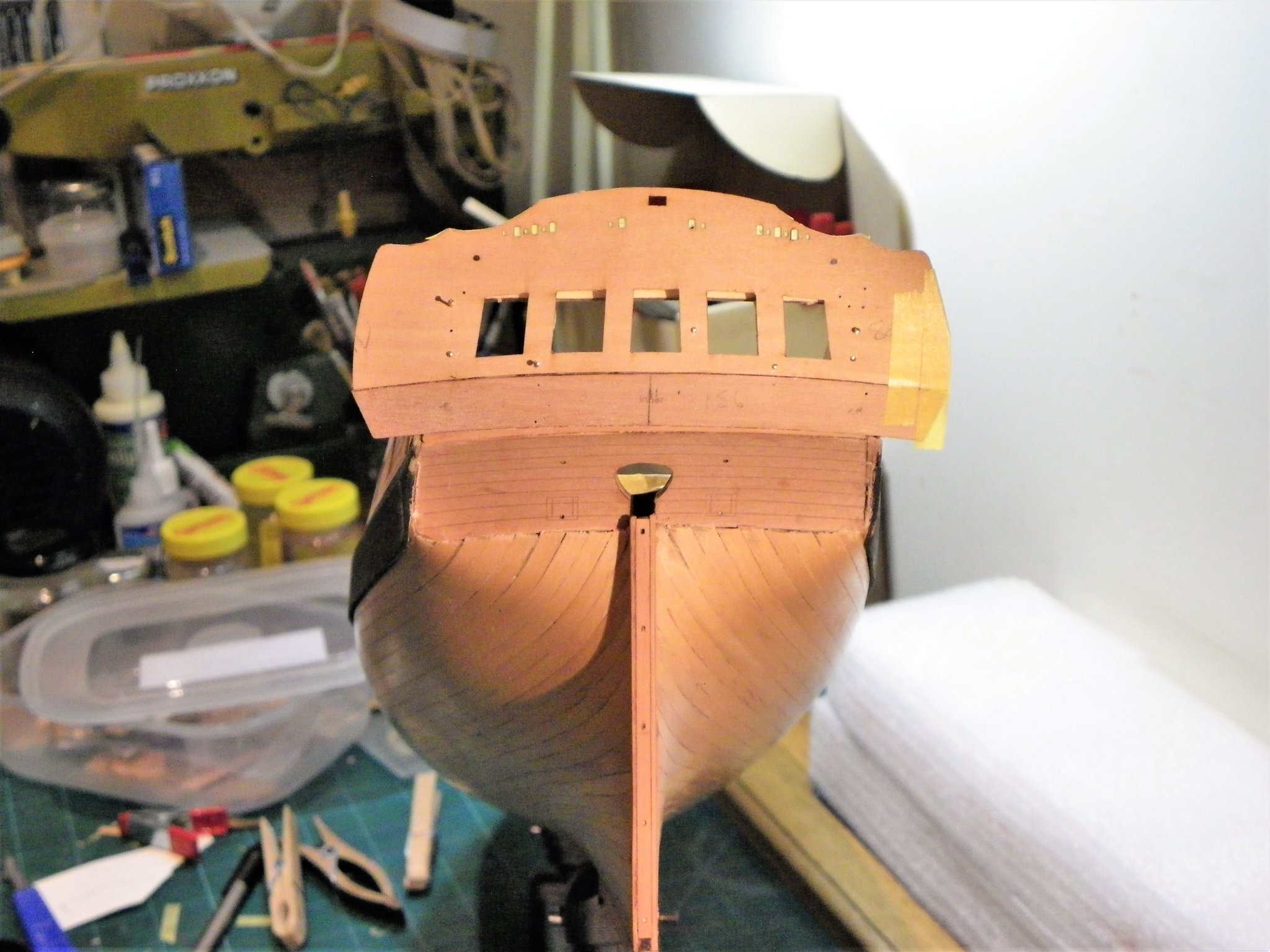
Post Forty-four That stern business I had intended to fit the port linings next, but with the stern patterns and Qtr galleries on my mind, I won’t settle until it’s sorted. I have to admit that I approach this task with a deal of trepidation. I have not actually fitted a Qtr gallery for over thirty years, Pegasus had a Badge, not a gallery, and that was tricky enough as I recall. This is one of the critical areas of construction with multiple parts requiring to be aligned. Additional self inflicted difficulties arise because my intention is to open up the galleries and install seats of ease, which means a deal of modification to the Quarter gallery patterns. Whether I can pull this off, or come to the conclusion that it’s not worth the effort I don’t know until I get into the assembly. I had done some preliminary work when I fitted the lower counter, so I will start with the Stern facia inner and work everything from that. This needs to be high enough to allow for the 1mm Quarterdeck rail with 1mm to spare. The Upper counter (inner) requirements will then be clear. The assembly will be looked at concurrently with the Qtr Gallery fitting as the top and bottom edges of the counter are critical to the mouldings that match up with those of the gallery. There will be a lot of temporary pinning and fitting before I finally commit to glue. To begin the process I separate all the parts relating to this area so they are handy to check fit as I go along. Identifying, locating, cutting, and sorting all the parts took a surprising amount of time. 1451 The Inner stern facia is pinned into place; tape is used to mark the line 2mm below the point where the bulwark meets the facia. A check is made to ensure the extensions are equidistant each side. The upper counter can now be tried in place. 1469 As can be seen there is a gap between Facia and counter, not unexpected but I need to decide whether to fit the upper counter hard against the facia or fill both sides. 1474 At this point I am also trial fitting the Quarter Gallery pieces to get a feel for how the assembly will hang together. 1465 I think I will bevel and butt the upper counter against the facia bottom, the lower gap is less important as is more easily filled and covered with a moulding. 1462 The line of the galleries suggests to my eye that the positioning is ok so tomorrow I will glue the facia and upper counter in place. B.E. 30/11/21


- 857 replies
-
- 19
-
-
- Sphinx
- Vanguard Models
- (and 1 more)
-
Hi Bug - on Pegasus I think I used thin slices from small diameter aluminium tubing flattened on the anvil. As I recall there was a big attrition rate to get the dozen or so required. @ Chuck - Thank you Chuck, I am leaning heavily on your wonderful Winnie build for ideas, and I hope to replicate the minimal planking pattern design of the Foc'sle and Quarterdecks. I do hope you don't mind. 🤞 Regards, B.E.
- 857 replies
-
- 2
-
-
- Sphinx
- Vanguard Models
- (and 1 more)
-
Exciting times👍 B.E.
-
Thanks Glenn, I think I meant 'Ironwork' black rather than 'dull' black, I used it on Cheerful as well. The dull black is just too shiny for my taste, it's an odd name given the effect. B.E.
- 857 replies
-
- 4
-
-
- Sphinx
- Vanguard Models
- (and 1 more)
-
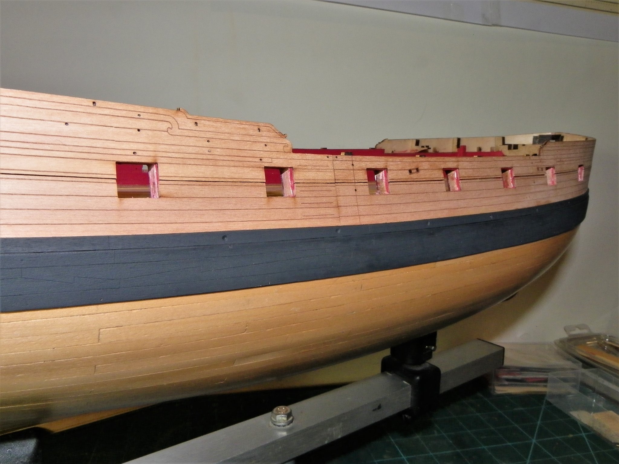
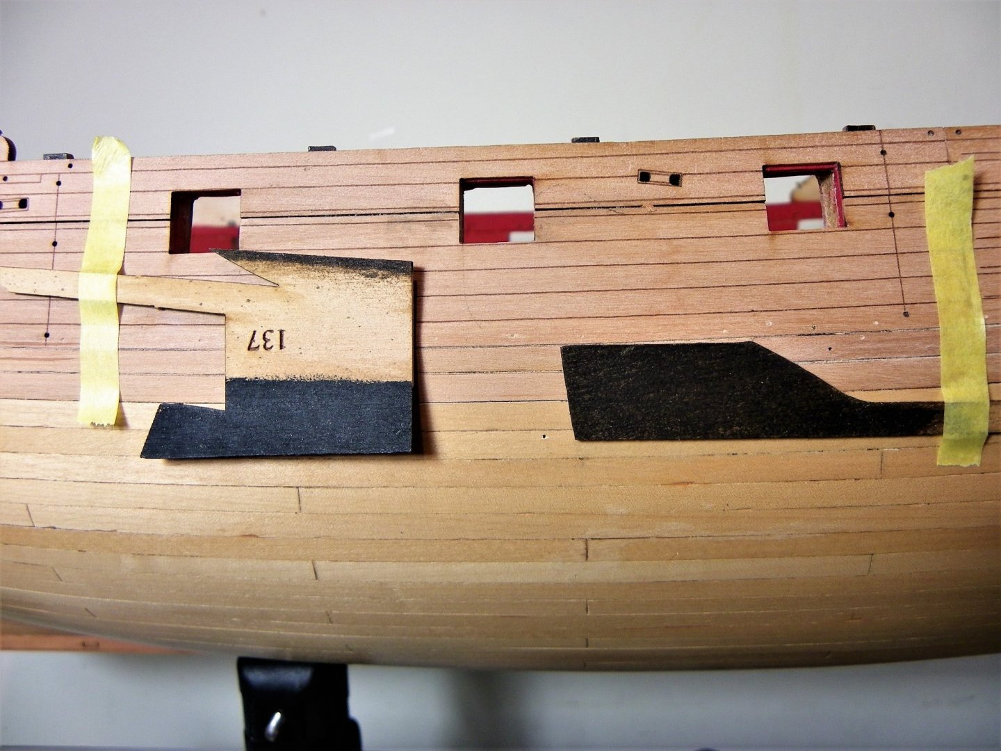
Thank you Thuky, I'm strictly a brush man, but I'll keep your advice in mind. Post Forty-three Completing the Wales. With the wales in position, the holes filled, it is time to think about colour. Damn! I’ve just realised that I forgot to thin down the back side of the wale strips for the first cm or so to give more of an impression of it fitting into the stem rabbet. Too late to do this now as it would destroy the planking lines, but I would suggest that future builders do this as it is more authentic. Before fitting the wales I looked at and trialled two different finishes as a change from my usual Humbrol matt black, or Admiralty Dull Black. These are Vallejo Black Grey and Colron dark Jacobean Oak wood stain. 1370 Vallejo Black/Grey (left) Colron dye (right) I dismissed the wood stain as it would have to be applied post fitting of the wale and it presented too high a risk of bleed onto the surrounding woodwork. I start with Vallejo Black/Grey thinking the less than hard black may provide a more scale appearance to the wale finish. Thin coats are applied as I am anxious not to hide the T&b plank lines. 1423(2) This is the result after two coats, I will leave it at that for the present. 1418(2) Wales do tend to get marked during the build process and there will be the need to apply more coats. 1420(2) Not set in stone, but I quite like the muted black effect. Above the wale is the black strake; not always black but on the Joseph Marshall painting of 1773 it is, so black it will be. The kit provides pre-spiled strips for these, no fitting issues but it is perhaps strange that the engraved plank butt lines match those to the top wale strake. This is of little consequence as they don’t stand out under the paint. I used ca to glue these strips to the hull. 1444 The outlets for the scuppers were drilled from without but I didn’t risk drilling completely through to the waterway. 1439 The flanges for the outlet pipes will be added later. 1437(2) The next job is to re-do the Port linings, what joy.🙄 B.E. 29/11/21
.thumb.JPG.b731e5d14496893107f231ae127fac10.JPG)
.thumb.JPG.ab1a91d540c5e5bf88ab12d21bf31aa2.JPG)
.thumb.JPG.baa4cefe258697e2af8082d0346b6903.JPG)
.thumb.JPG.6ebba0a6723dcf0733ff53e8e153aebc.JPG)
.thumb.JPG.aa6a5b27832eb3c8dc95a5b8d890bb6c.JPG)

- 857 replies
-
- 19
-
-
- Sphinx
- Vanguard Models
- (and 1 more)
-
I wish I could offer some incisive comments and useful thoughts on the Quarter gallery construction, but I have little idea at this point, and the thought of building them is giving me the yips.😕 Your experience will no doubt prove invaluable to me. B.E.
- 505 replies
-
- 6
-
-
- vanguard models
- Sphinx
- (and 1 more)
-
Beautiful work Rusty, those Quarter galleries are a wonder to behold. Great artistry. B.E.
- 642 replies
-
- 1
-
-
- winchelsea
- Syren Ship Model Company
- (and 1 more)
.JPG.5b085a9c2df75d851d914cd31ae06329.JPG)


.JPG.35216e035a2f3a0ff73f82f534399dc9.JPG)

.JPG.a8da7d8b05e5556cbfcd9be13fb19b4a.JPG)


.JPG.8ab8de6965c0157b124be1e871f68f22.JPG)
.JPG.f1e102d73dc6c4c313a453fb0184311f.JPG)


.JPG.4f07a88fd9bf7aa8ca00dbc266ed5be8.JPG)


.JPG.783626970c0ae5909fb2e5f5ddf07f3f.JPG)
.JPG.b259f9142f561cfdd4d484f1fd5b972a.JPG)
.JPG.fcb4d54b39718ffb9eee299d0164cbd0.JPG)
.JPG.55a4cd7eaecb350c919b7a1110d6b721.JPG)
.JPG.26507ad01d5994d69924ece36c901803.JPG)