
.JPG.ca33079f5815b861e67b9c2cccd37982.JPG)

Blue Ensign
-
Posts
4,575 -
Joined
-
Last visited
Content Type
Profiles
Forums
Gallery
Events
Everything posted by Blue Ensign
-
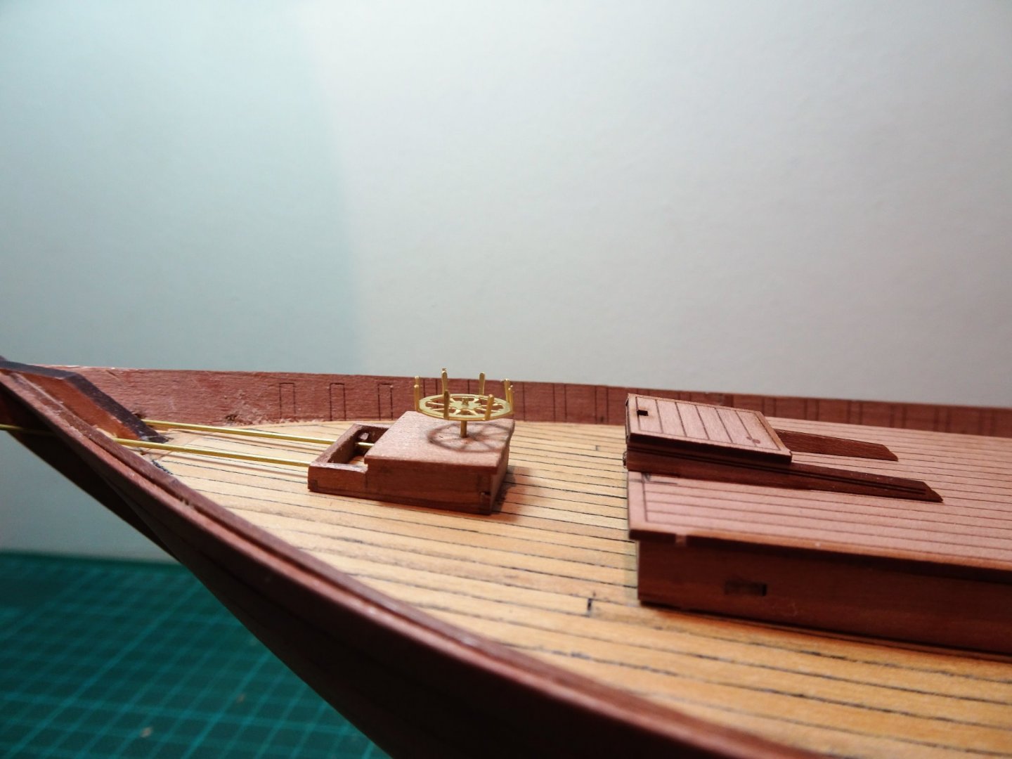
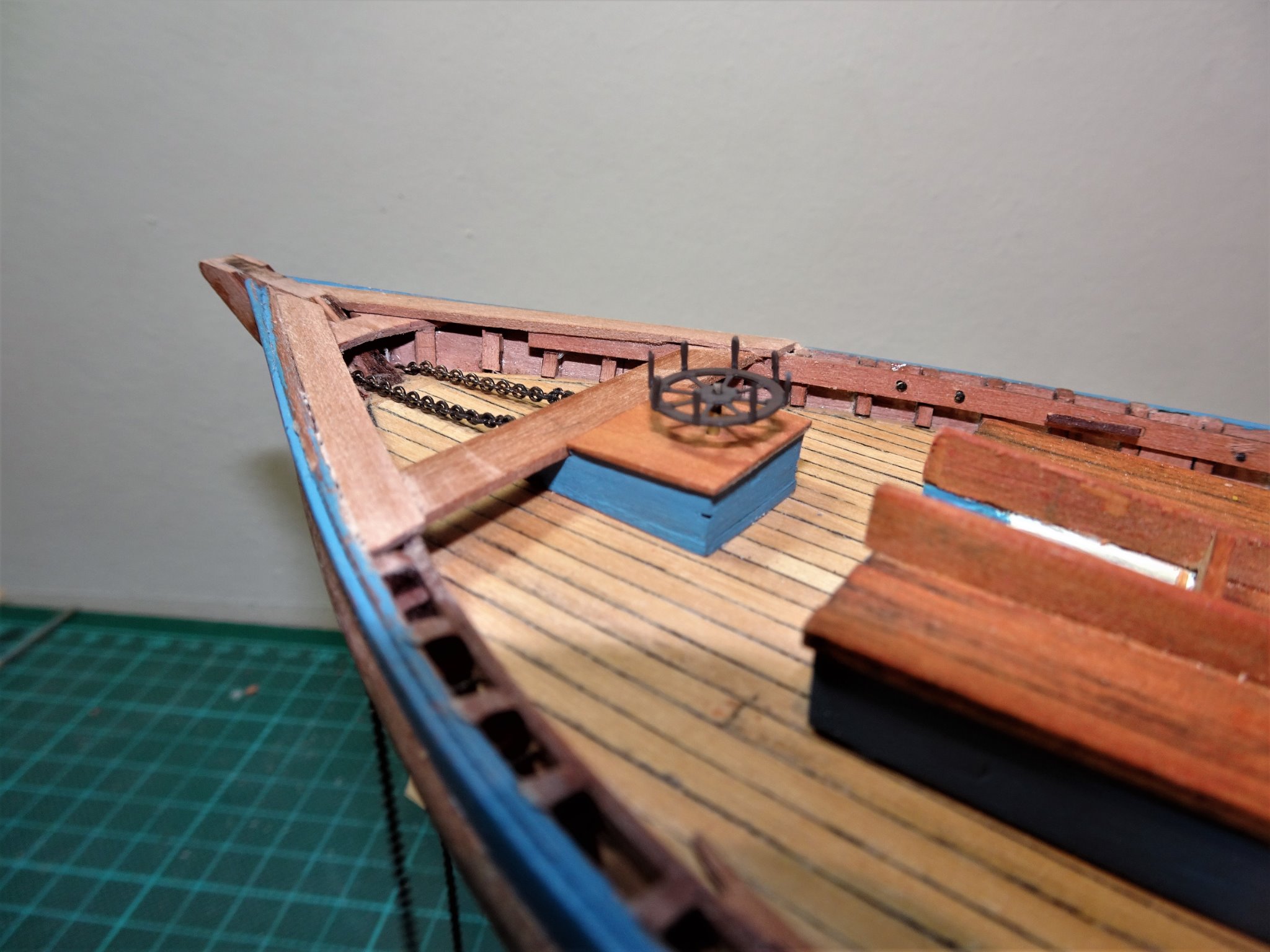
 Post 21 Fitting the Steering Box. The Steering Box and related fittings present the most fiddly modification. The kit has a simplified all in one bench pattern (51) which incorporates a knee at the stern, doubler, and aft thwart against which the steering box butts. Muirneag differs both in the size and position of the steering box and the layout of the thwart, knee and doublers. There is a fair bit of trial fitting to get it all to sync together involving making separate parts. The first job is to get the position of the steering box fixed and to cut away some of the stringer to allow the aft thwart to sit down just below the level of the rail top. 7931(2) A spacer is used to position the box the correct distance from the companionway. 7922(2) The next step is to work out the run of the rudder chains thro’ the hull to the steering rods which protrude beyond the box. This particular chain I discarded in favour of a finer version with 26 links per inch. With that done the box can be safely glued down along with the aft thwart. 7934(2) The tricky business of shaping and fitting the doublers and stern knee can then be done. Why 'doublers' I don't know, they are for all practical purposes rails. For the doublers I am using 4mm Pearwood strip, edge bent to suit the line of the stern. These need to sit flush with the top rail line. 7947(2) Trial fitting the wheel, it always helps to have a scale figure handy. 7945(2) The height of the wheel above the box has been reduced as covered in Post 13. 7975 The wheel is quite a delicate item, so the stem slots into a micro brass tube fixed in the steering box which allow for its removal. 7978(2) It is a slightly simplified design with the spokes radiating from the hub simply bent into the vertical position to provide the hand grips. In reality the spokes extended beyond the rim and the hand grips were either bolted or welded in position. To replicate this at 1:64 scale would be a stretch too far for me. I will leave the final cleaning up of this area until the rudder is fitted which is the next task. B.E. 18/10/20
.thumb.JPG.2e0b84be3a70fe14f6d66b10ca1d70ea.JPG)
.thumb.JPG.bb94fb9308b24a23d948afc99c7fc27c.JPG)
.thumb.JPG.583ae0df452c41c6bc48db5d6309c850.JPG)
.thumb.JPG.3491feecd1172e891349456df72309a5.JPG)
.thumb.JPG.0b3152c869f1b991e979dde7e68f729f.JPG)

.thumb.JPG.2713819ab3d83196261e565ec83a363a.JPG)
- 261 replies
-
- 16
-

-
- muirneag
- vanguard models
- (and 2 more)
-
She looks good in the traditional black livery Richard, and the grey decks should provide a nice contrast. 👍 You have provided modellers with a good impression for those hovering between natural and black. 🙂 B.E.
- 49 replies
-
- 1
-
-
- Lady Eleanor
- Vanguard Models
- (and 1 more)
-
May be a blessing in disguise Tim, the kit provided stocks didn't look right to my eye, replacing them with the pattern in the aots book is the way to go.🙂 B.E.
- 436 replies
-
- 3
-
-
- vanguard models
- alert
- (and 1 more)
-
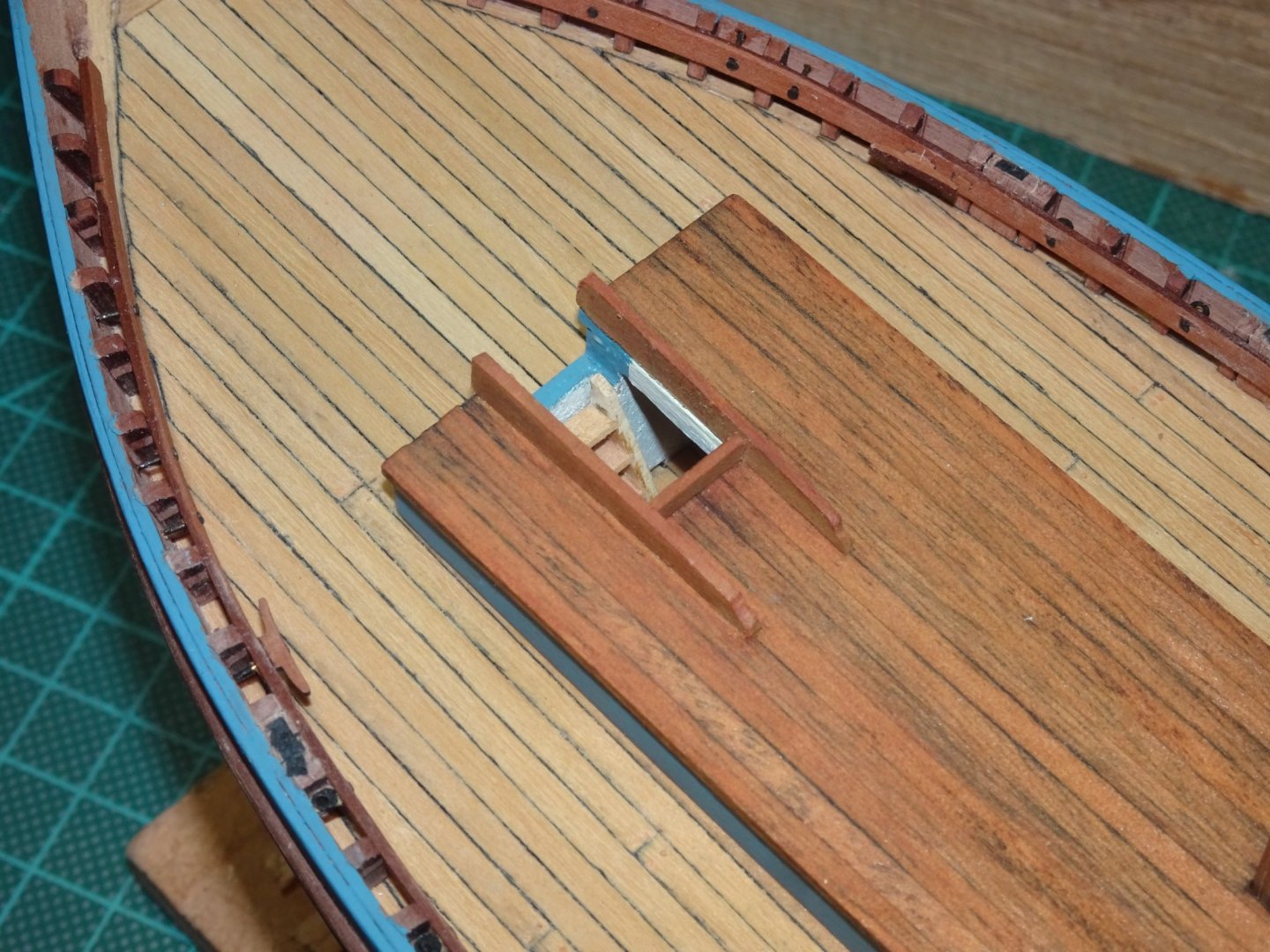
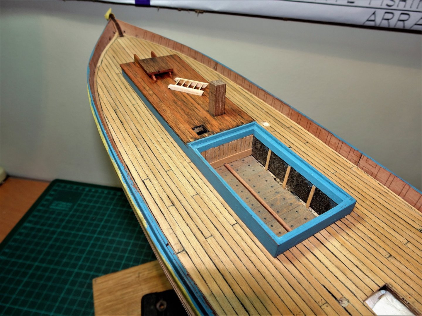
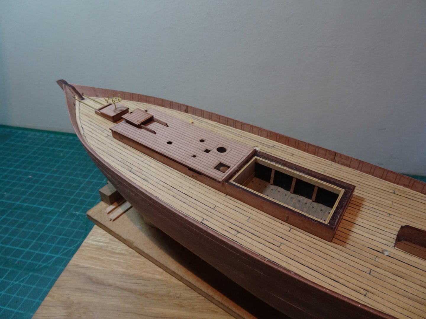
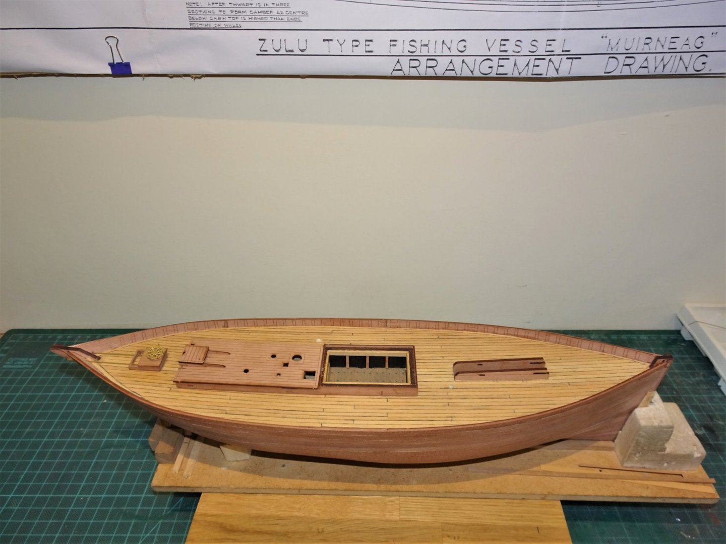
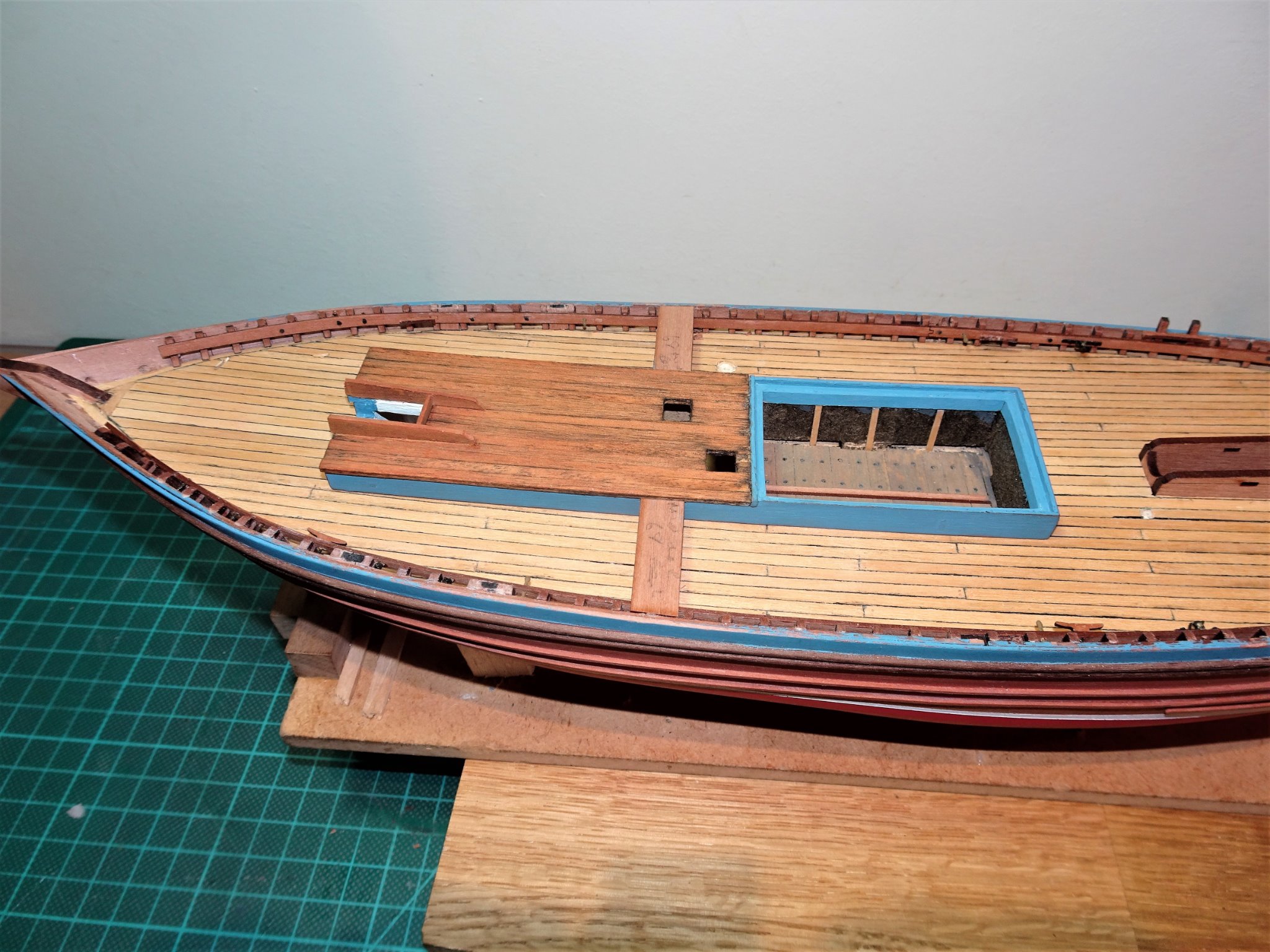
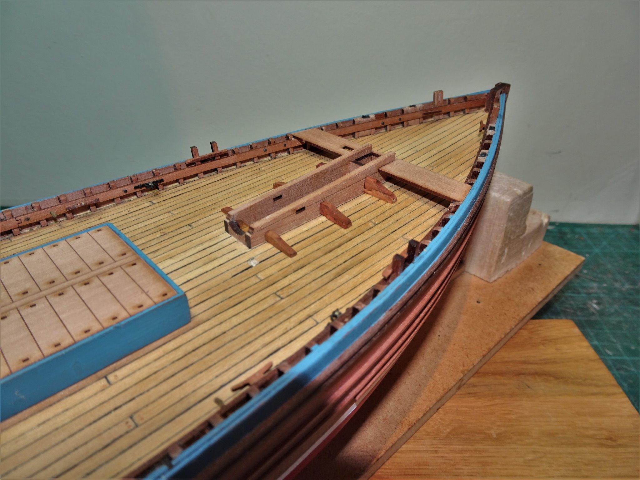
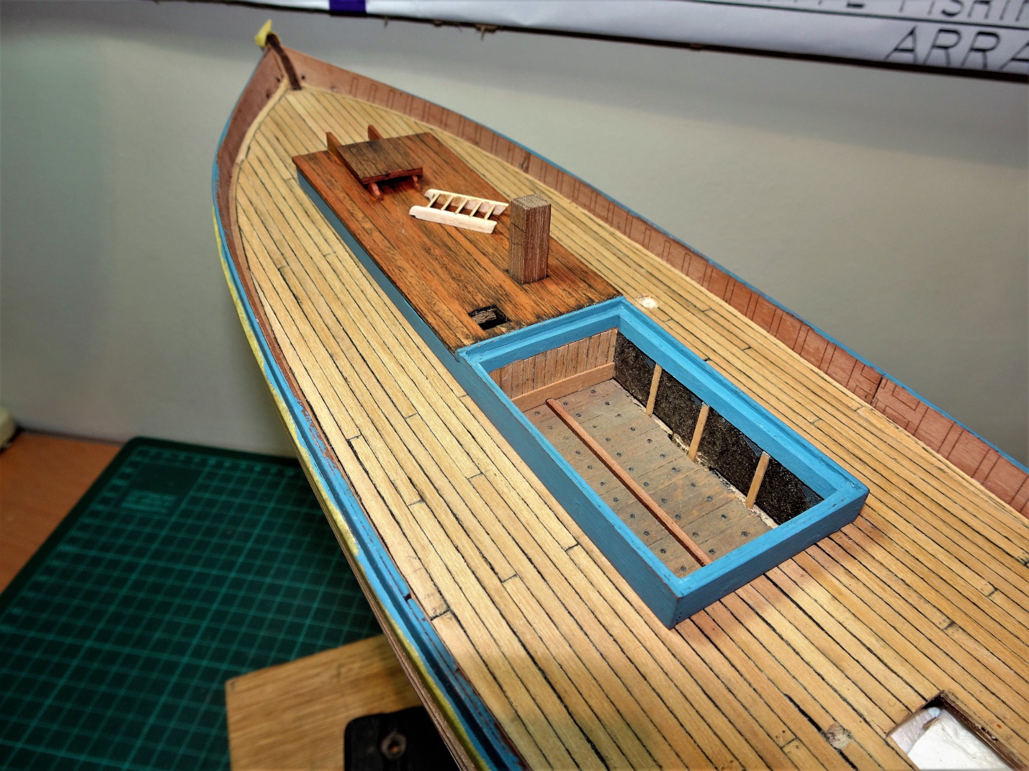
Post 20 Poop Deck and Fore-mast partners. Before these are finally glued into place it is worth test checking the fit of the Fore thwart and Mizen thwarts. These should fit down on the stringers, and back to the bulwark. On my build I had to chisel the timberheads flush with the stringers to achieve this. In reality the thwarts appear to be mortised thro’ the top rail, which is reflected on the plans and the representative models of Muirneag. 7848 On Muirneag the Mizen thwart runs as a straight board, whereas the kit provided version has a flared outboard end. These extensions were removed for the purposes of my build. The kit Fore thwart is a good fit to the mast partners. 7849 The timberheads were cut away above the stringers to allow the thwart to sit fully down. 7852(2) 7850(2) The Poop deck and Fore-mast partners are now glued into place, no issues with fit, and it is a nice touch that Chris provided a decking section below the partners. The 8mm square Foremast fits perfectly between the partners and the mast stop. 7871 I decided to add the Foc’sle ladder which sits just inside the inboard end of the partners. 7870 Even with the mast lowered and resting on the crutch adjacent to the Mizen mast there is still access to the ladderway. The kit has a separate fore hatch which seems a more practicable arrangement and one that is evident on the plans of other Zulu’s. A question mark appears over the number and position of the partner knees on Muirneag. The Underhill plan shows only two each side with a cleat between them. This is reflected on the NMM model, but not the Gordon Williams model which has three. The clincher is that a photo of Muirneag does indeed show three evenly spaced knees. (p288 Sailing Drifters.) but rising in depth as the partners get wider towards the fore part. 7901 Modified knees in place. 7907 The thwart is only trial fitted here. I can now fit out the fish hatch. 7857 Removeable Partition boards used to arrange and distribute the catch in the hold to suit the trim of the boat. 7854 Net platform boards installed. 7855 This is as far as I can take the fish hold detail, and most of this will be covered by the nets. 7860 The companionway ladder can now be fitted. I will next move onto the steering fittings. B.E. 16/10/20

.thumb.JPG.c4e01373deda28f0dbbd49049f5c9829.JPG)
.thumb.JPG.3215b783f0378a351a5037417cbb153d.JPG)


- 261 replies
-
- 11
-
-
- muirneag
- vanguard models
- (and 2 more)
-
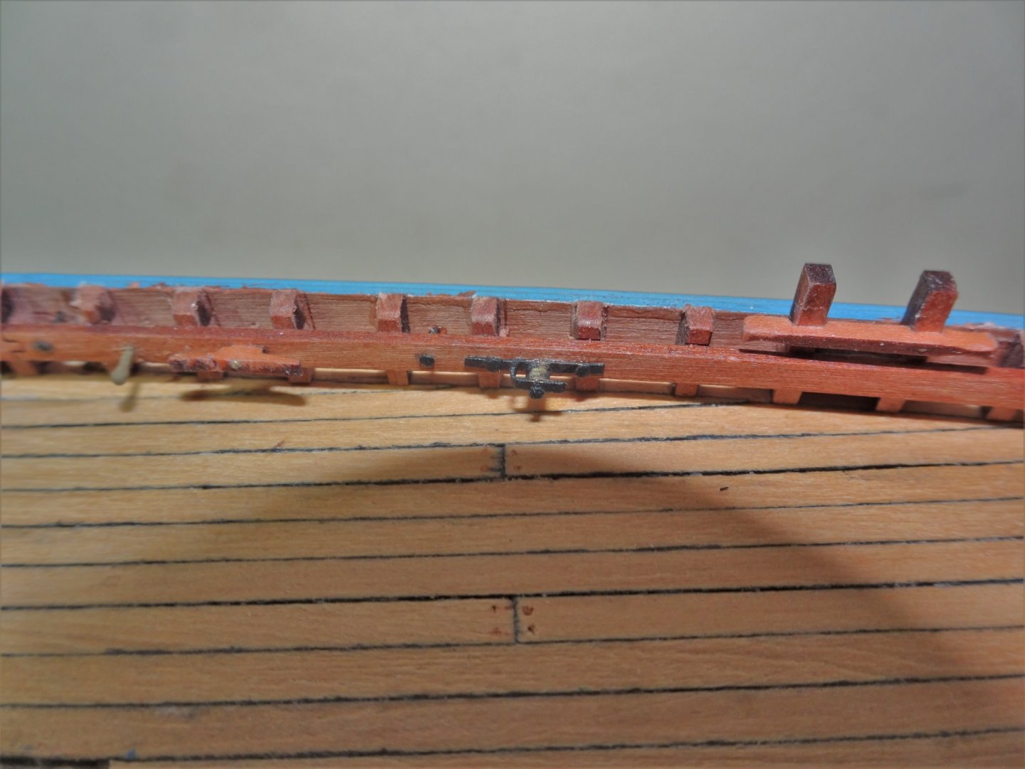
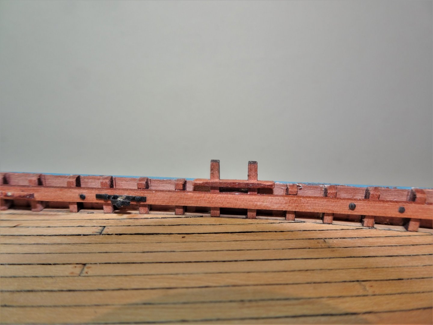
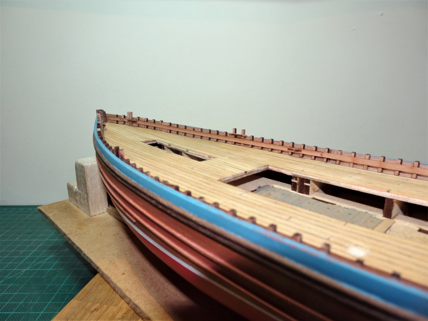
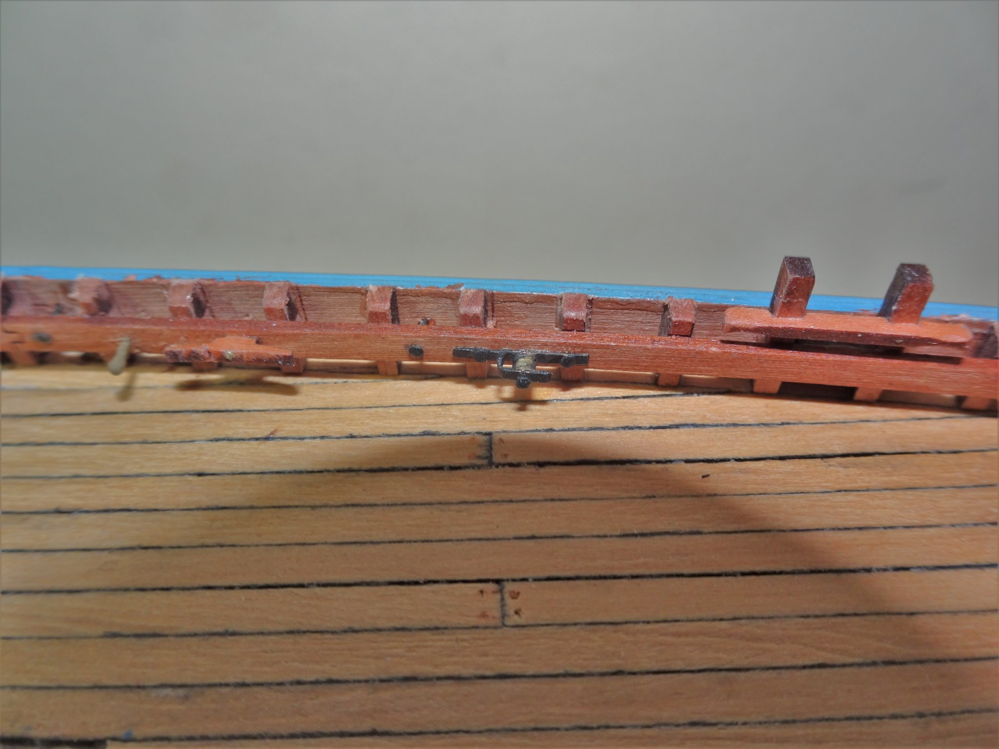
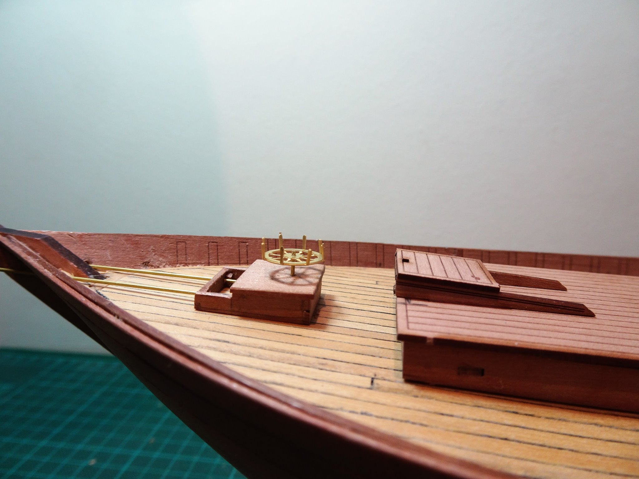
Post 19 Completing the rail fittings All this work is best done before any of the deck fittings are put into place to give best access for drilling holes in the stringers. I have now added the bolts that provide hooking points, and the metal plates to the doublers. 7833(2) Metal bolts thro’ the stringer to provide belay points. Cross pieces have been added to the cavils. The Underhill plans show metal sheaves Port and Starboard for the Fore and Mizen halyards. 7826(2) These are interesting features but I needed to work out an assembly method given their very small size. One of the four belaying pins inserted horizontally through the stringers can be seen aft of the large cleat. For these I used the brass etched versions provided with the Alert kit but enhanced slightly. 7827 The sheave bracket was silver soldered together using thin brass strip, and the sheave is represented by a section of brass tubing. 7833 The completed items are only 9mm long x 1.5mm deep. Most of this stuff wouldn’t be noticed by the casual observer, but it is on the plans, and if I can add it I will. 7845(2) A final repaint of the top rail and I can finally move onto fitting the Poop deck and Fore mast partners. B.E. 14/10/20
.thumb.JPG.16a1ee0eaa116cea2e6ce5438d54e876.JPG)
.thumb.JPG.d115c79ad52c51fe38486128197df172.JPG)
.thumb.JPG.45c0dd606d3edbeded3675eba71780a9.JPG)
- 261 replies
-
- 18
-
-
- muirneag
- vanguard models
- (and 2 more)
-
You're right to be pleased with the stern Glenn, you've made a fine job of it. 👍 B.E.
- 778 replies
-
- 3
-
-
- cheerful
- Syren Ship Model Company
- (and 1 more)
-
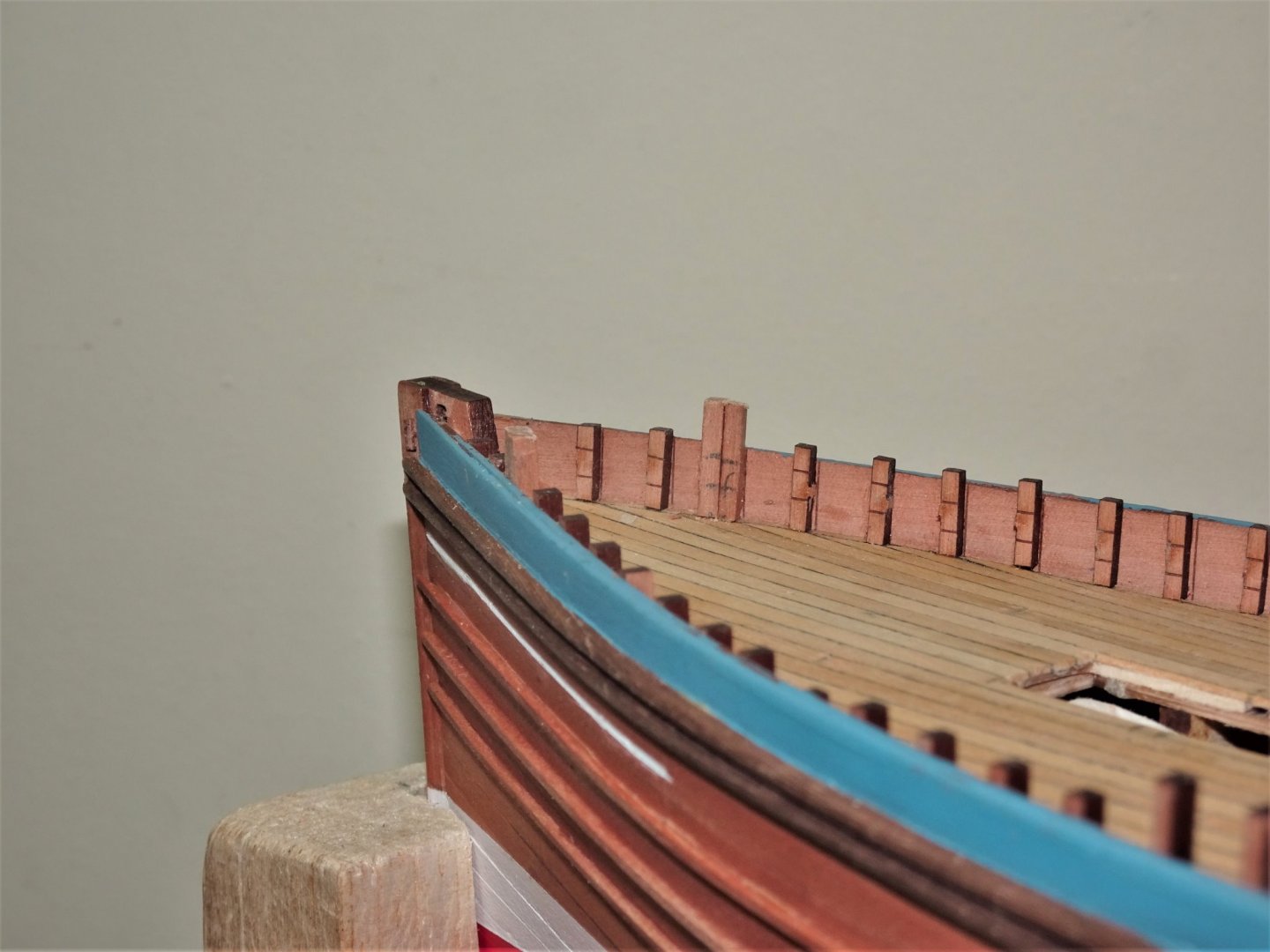
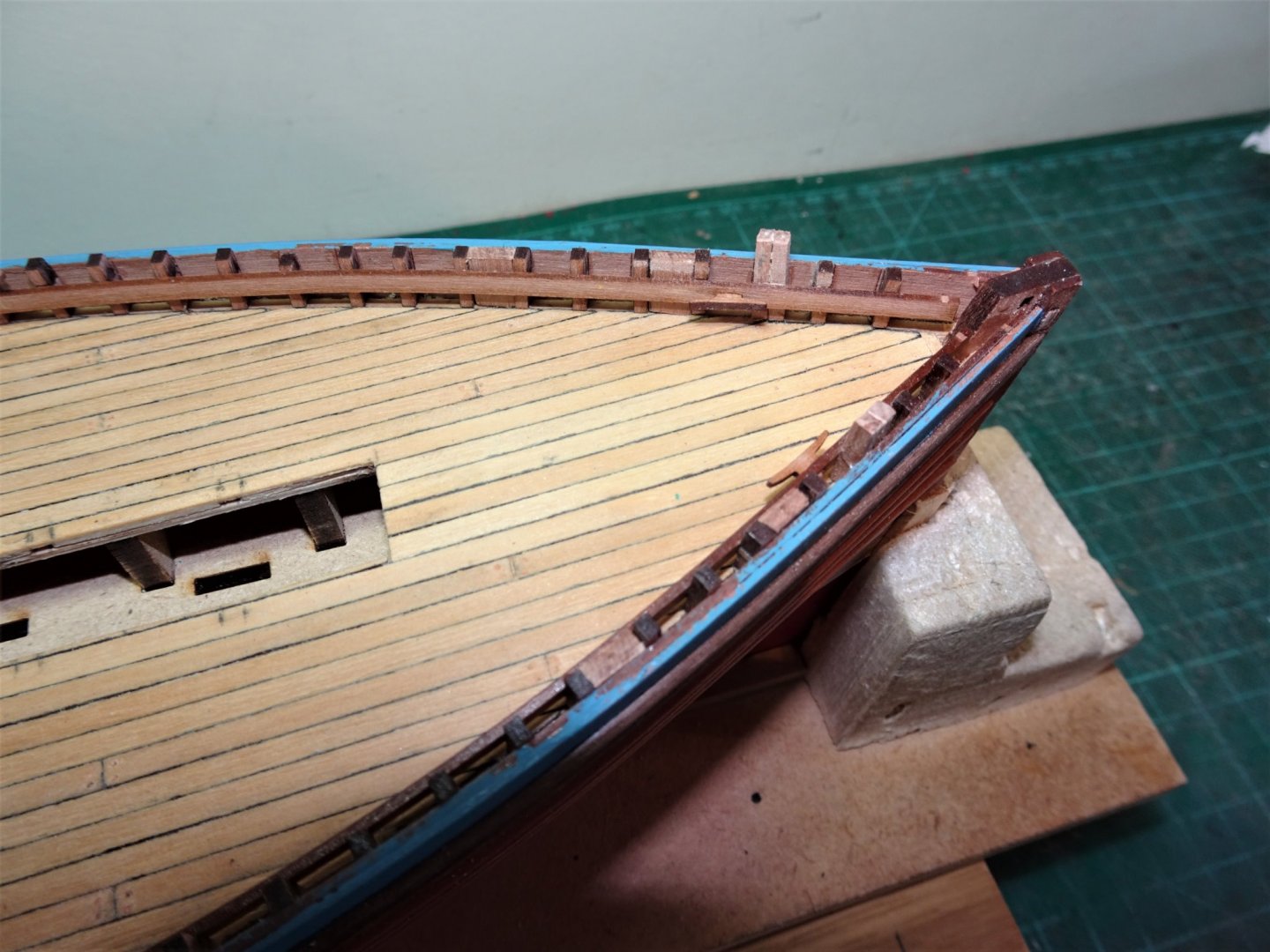
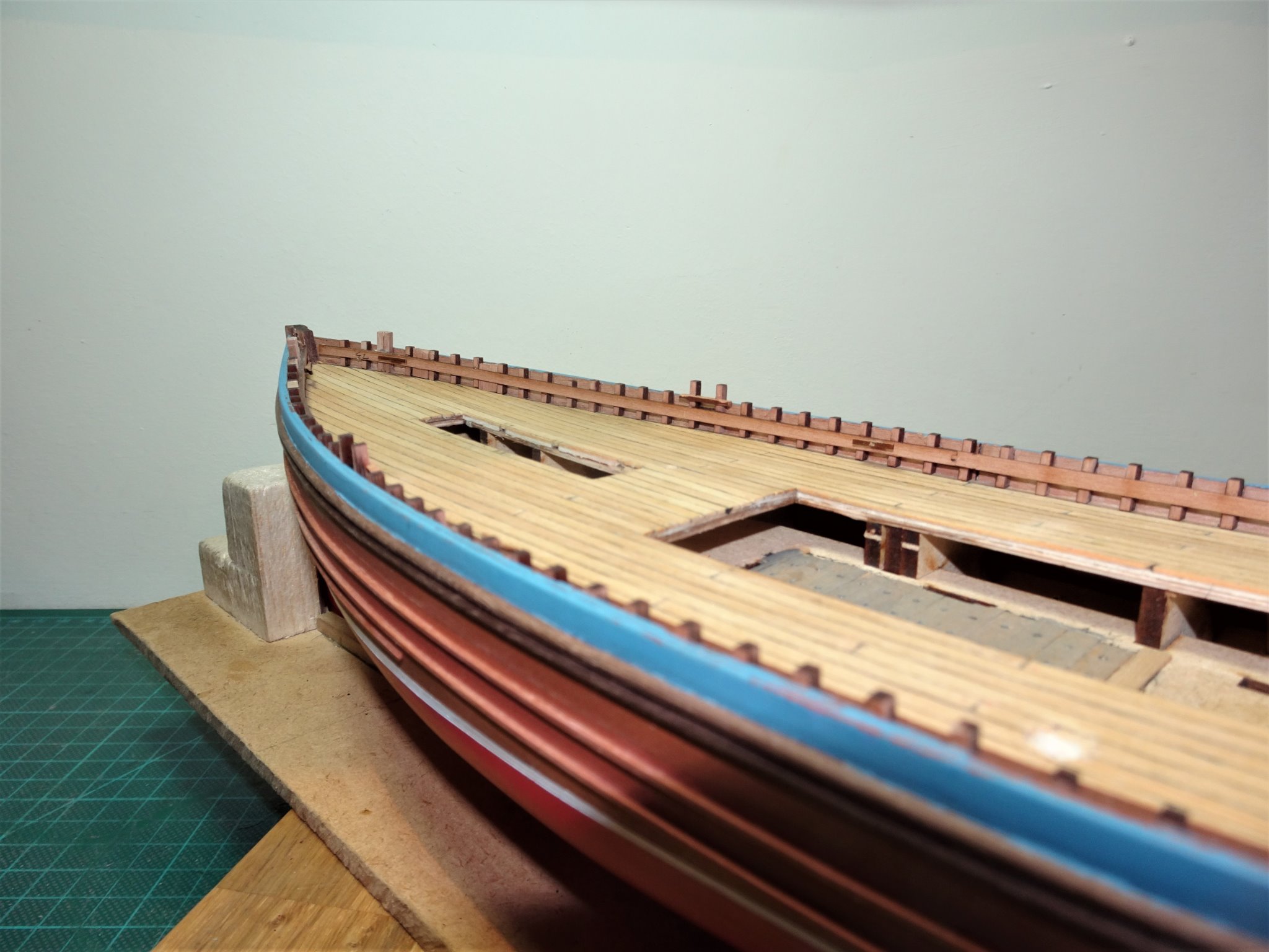
Post 18 Timberheads and stringers. There are 98 tiny laser cut Pearwood timberheads to be glued to the bulwarks, all handed and position specific, so each one has to be removed from the fret and glued individually before removing the next. 7713 A tiresome business, but quite an ingenious method devised by Chris, and one that relieves the builder of the even more tiresome business of individually cutting small sections of square stuff. 7712(2) It is also a nice touch to have the line of the stringers etched into the face of the timberheads. The kit includes the major features along the bulwark, cavils, and cleats, but one slight puzzlement I have is that the cavils, provided as part of the timberhead set, don’t include the cross pieces. This is easily rectified however, using pieces from the fret. The Underhill plans show a wealth of additional fine detail which it is feasible to fit at 1:64 scale. 7715 One immediate modification is the replacement of a single timberhead at the bow with a double timberhead rising above the rail. The Pearwood stringers are attached next having been adjusted for Muirneag specifics. 7733(2) These affect the aft section of the stringers where the morticed positions of the large cleats are filled in, and sockets are added to the back side to take the side light brackets. 7730 With the stringers firmly glued there are a series of infills between the timberheads, called doublers on the plan, these are topped with an iron plate and a socket to take a “ spring warp cage” whatever that is; something else to research. 7729 In this shot the cross pieces have been added to the cavils, and the blocks that form the doublers are in place behind the stringers. 7742(2) The Stringer cleats are now in place but except for the foremost set are repositioned to suit Muirneag. 7739(2) 7740(2) The timberheads now need to be sanded level with the rail and the fittings cleaned up. The final task will be to add a series of bolts through the stringers which act as attachment points for purchases and rigging, and holes drilled to take horizontal belay pins. B.E. 08/10/20
.thumb.JPG.21366cdda9c0f55fe2604fb2141c100b.JPG)
.thumb.JPG.62e5537bab72a9e518f3c4ee92b176d9.JPG)
.thumb.JPG.5958395ab7254a5441a6f692fdfe097d.JPG)
.thumb.JPG.66ac0b65f7466e7afbd4cd38430418cf.JPG)
- 261 replies
-
- 12
-
-
- muirneag
- vanguard models
- (and 2 more)
-
I've had a look at that model Tony, and I see what you mean. It does look a very interesting project and I see that Ancre has a publication out on the vessel. I'm sure you will do the subject justice, I've picked up more that a few tips from your builds. 🙂 Cheers, B.E.
- 261 replies
-
- 2
-
-
- muirneag
- vanguard models
- (and 2 more)
-
Some great stuff comes out of that Chittenango shipyard, and this latest offering is no exception. Beautiful work, Rusty. B.E.
- 642 replies
-
- 4
-
-
- winchelsea
- Syren Ship Model Company
- (and 1 more)
-
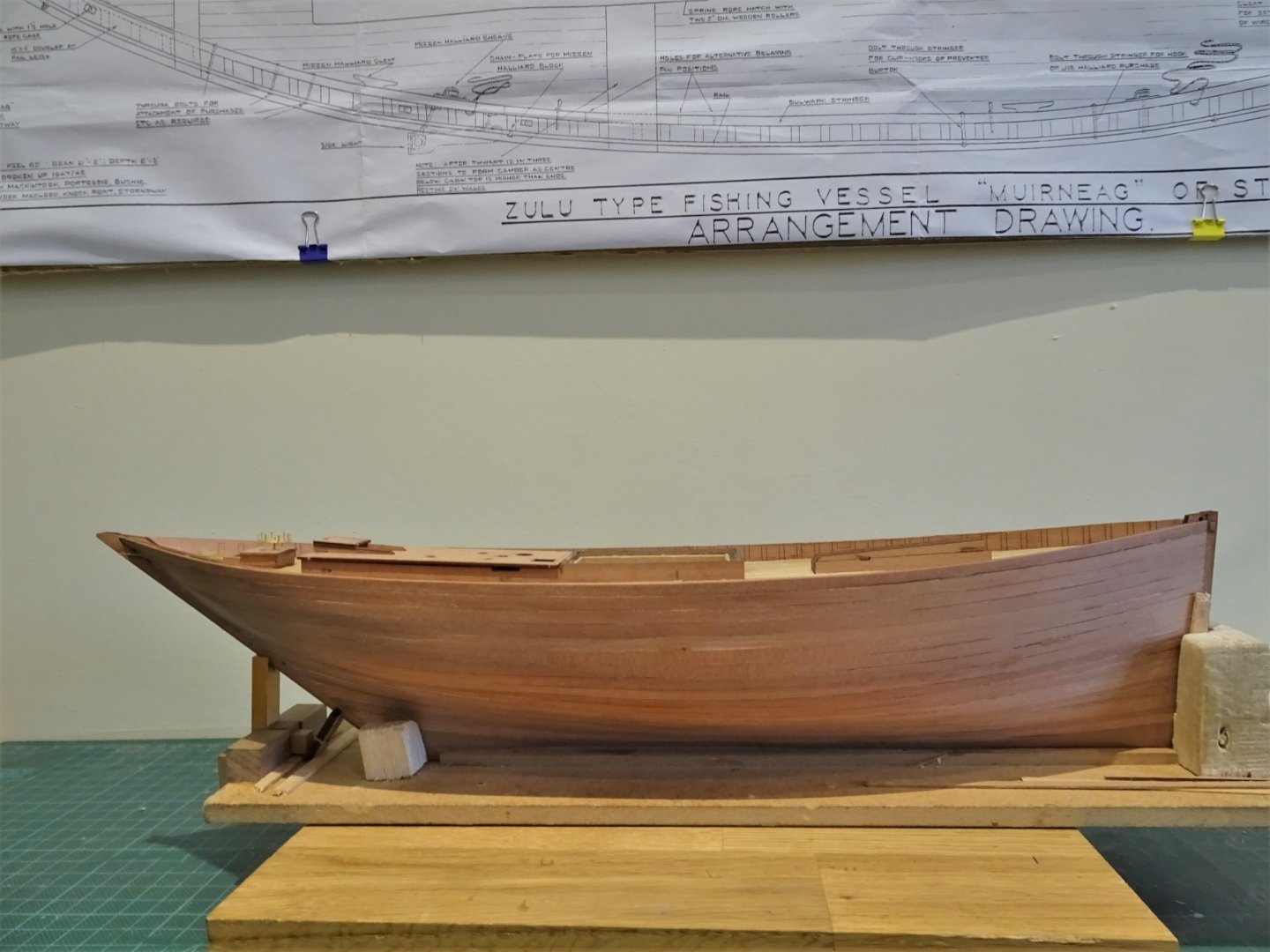
Thank you Yves, Martin and John. I am now at the point where I can relax a little and enjoy the fitting out. @ Martin Rubbing strakes are a pain and it does help to have something on the hull to guide them. She would look quite impressive painted as evidenced from the splendid model by Gordon Williams. He did have the best of both worlds as the Starboard side is unpainted with large sections of the hull unplanked to show interior detail. A point of interest is that a bilge keel is shown which isn’t evident on the Underhill plans but which also is shown on the NMM model (George Macleod) Old photographs would suggest that Bilge keels were a feature of fishing boats of the era. I need to decide whether to retro-fit one. The Zulu is in effect a hybrid design combining features of two of the prominent designs of the time; the Scaffie fishing boat (Sharply raking stern) and the Fifie (which had a straight stem) In any event it became a highly successful design, favoured by many of those engaged in the business of fishing. B.E.
.thumb.jpg.a47b6b9a425dc503484191f0394f33ba.jpg)
- 261 replies
-
- 11
-
-
- muirneag
- vanguard models
- (and 2 more)
-
That looks excellent Erik, I think you're a natural at this planking business. Well done👍 B.E.
- 222 replies
-
- 3
-
-
- First Build
- Lady Isabella
- (and 2 more)
-
Cheers Guys, @ Glenn - Fun is not exactly how I would describe it😄 @ Bob - Glad you're enjoying it. 👍 @ Jean- Paul - The Vallejo flat red really seems to suit the Pearwood. I hesitated before adding the Blue, but it was a feature of the real thing. 🙂 @ Tony - Glad to have helped, but I'm not quite sure how the sequence relates to the wale and waterline on this particular model.🤔 Post 17 A step forward and a step backwards Re-visiting the Fish hold. I thought initially that I would get away with leaving the fish hatch open as is with some interior detailing. 7438(3) The problem is that on the kit it was designed to be closed, and the mdf carcase is way over scale for the true thickness of the hatch coamings. 7659(2) My eye wouldn’t let me rest so there’s nothing like a spot of Sunday morning de-construction to sort things out. Not difficult to pare down the mdf, it is soft and comes away easily, I should really have done this in the first place. I know some people don’t like mdf but for carcase construction I love it, its use is of great benefit to the serial kit basher. 7693(2) Most of the interior fitting out can’t be done until the carcase is fitted. Progressing the Poop 7706(2) Boxwood planking has now been applied to the Poop deck, and a ladder was constructed for the companionway as the hatch cover will be slid back. I spent some time mulling over what colour to apply to the planking. The scheme indicated is black varnish, which explains the colour scheme used in the NMM model (George Macleod) and the models made by Gordon Williams, and Jan van den Heuvel, all of which provide a valuable reference source for my build. I tentatively tried Dark Jacobean oak dye but it didn’t work for me. 7690(2) I finally settled on Pitch pine wood dye which provided a contrast to the deck and I thought suited the scheme overall. 7693 All the required fittings for the Poop deck of a Zulu are provided in the kit. In addition to the Companionway these comprise the mast partners, the Foremast crutch, The Warp hatch and rollers, the steam Capstan, and the flue pipes that would serve the boiler and galley stove. Modifications to suit Muirneag involve squaring the Mizen mast base (the mast is square section to just above the deck) and tweaking slightly the positions of the other fittings. 7708(2) The major alteration to the poop was the repositioning of the companionway as covered in Post 12. 7705(2) 7667 In these shots the rudder is slotted into place; I think it makes a big difference to the overall look of the hull. I won’t however be using the simplified kit arrangement when I get around to fitting. Before the Poop deck assembly is finally put into place I will attend to the timberheads and bulwark stringers. B.E. 04/10/20
.thumb.JPG.f1c043bab283af60d2cdf00693269431.JPG)
.thumb.JPG.b19d2dea1ae203f8ed2908de42c95835.JPG)
.thumb.JPG.44b5745e2cea0044a06df79cee172fbd.JPG)
.thumb.JPG.799ffb59337565775c2f1e7708723eea.JPG)
.thumb.JPG.d59873da73483654a7eba65510ea97a8.JPG)
.thumb.JPG.350eeba7500b33174066ef8da991d66a.JPG)
.thumb.JPG.7552e9da23af579f94c10e671d398b97.JPG)
- 261 replies
-
- 14
-
-
- muirneag
- vanguard models
- (and 2 more)
-
Thank you Guys for your supportive comments and 'likes' Post 16 Time to add the rubbing strakes. The gunwale rubbing strakes are represented by two 2mm half round walnut strips. On the real thing these are the gunwale a 7½” x 4½” timber faced with two half round iron strips. The kit arrangement is not a bad visual interpretation of the wale. The kit manual indicates that the gunwale strip is placed 4mm below the bulwark top. In practice this appears to follow the line of the top Pearwood strake. Below the wale there are three rubbing strakes, (the beads) also faced with iron. These are represented by 1mm walnut strips. I did think about replacing the strips with blackened half round brass strip but looking at old photo’s of Muirneag I decided the effort wasn’t worth it. A key issue with fixing these strips is to get the correct angle of cut where the strip meets the stem and stern posts. 7596(2) I use ca to fix the strip and ran a length of Tamiya tape along the top rail to protect it from any overspill. I also have acetone and a small brush ready to wipe off any excess. 7599(2) The second strip is placed immediately below the first which is less of an issue. Lower 1mm strakes The first of the three lower rubbing strakes is placed 6mm below the wale strip which allows for the Registration number to be accommodated. I will use BECC 5mm self-adhesive lettering for this. The second strake is set to be 4mm below the first. 7603(3) I use sections of pearwood planking to guide the position. 7609(2) Sample lettering 7613(2) First two strakes in place I found fitting these strips a little tricky, for most of the length from the bow it is parallel to the Wale but towards the stern there is a subtle upward curve to the strip and a reduction in the width between the strakes to 3mm. Note: 1mm Walnut strip is not the best material to work with and requires careful handling. The kit provides only 5 strips, to meet the exact requirements. No allowance is made for less than good lengths, and should the need arise to reposition an already glued strip, there is a high risk of breaking it. A couple of extra strips included with the kit would be of benefit, I think. 7617(2) The third strake only runs 140mm from the bow, which accords with the Underhill plans. Again I used Pearwood strips to aid positioning. A final addition to the hull is an incised groove centred between the wale and the first rubbing strake and running from the stem to the Registration number. 7614(2) The cut was made using scalpel and files and through masking tape to reduce any risk of the line running off grain. 7627(2) 7635(2) 7623(2) 7634(2) 7638(2) I worked a day and a half fixing these tricky little beggars and there is still work to do re-touching the paint lines and cleaning up the hull for the application of wipe-on -poly. B.E. 03/10/20
.thumb.JPG.b350b1baebb9046f256af1adff4fa280.JPG)
.thumb.JPG.a1338167005efa30be037d3fbb2ecb0d.JPG)
.thumb.JPG.26ba0f4d9d962dd4e302676c99ce1f1c.JPG)
.thumb.JPG.fa8cf7023ddb6fb84ce20641704e3f20.JPG)
.thumb.JPG.d62c2373da8439cbdd32447074d4f943.JPG)
.thumb.JPG.3230406158be74ed1e4246b3f292dd18.JPG)
.thumb.JPG.f4ec7fb40c3287b281b195258dd33b7a.JPG)
.thumb.JPG.74d4e2b671363fcba2f916dfee266177.JPG)
.thumb.JPG.7d46ba5d44a1751f8aac8b5065c75bcf.JPG)
.thumb.JPG.03823dbfe0920de81365671b4fe301ca.JPG)
.thumb.JPG.963cabff96114c4a3b10d584278fee1c.JPG)
.thumb.JPG.6f7f44798f3741f2ca4468b59dc8ab7f.JPG)
- 261 replies
-
- 16
-
-
- muirneag
- vanguard models
- (and 2 more)
-
Your planking looks very good Eric, and will provide an excellent base for the Pearwood. One piece of advice I would offer is to ensure that on completion of the first planking you fine down the plank ends at the bow and stern to be flush or even slightly below the stem and stern posts. It is useful to use the Pearwood stem and stern patterns temporarily in place to check progress, and see how the pearwood planking will fit. It is much easier to sand the limewood than the Pearwood, and the object is to avoid at all costs a ridge running down the stem and stern lines. Regards, B.E.
- 222 replies
-
- 4
-
-
- First Build
- Lady Isabella
- (and 2 more)
-
Post 15 A little more progress on the paint front Adding the line for the watercut is fairly straightforward with the waterline marked. 7587(2) Just requires some careful masking. 7595(2) The Top rail is painted blue (Underhill Plans) which is a common theme running thro’ all the models of Muirneag, and I have followed suit. I used Humbrol 89 darkened a little with Humbrol 25. Far from the impression given by dark b/w photo’s from bygone years, descriptions from the time note bright paintwork was a feature of Zulu’s, and Fifie’s too I suspect. 7588(2) The framing for the Poop deck is also painted blue, still dry fitted in this shot. 7590(2) The false deck has now been fitted to the poop framing and will be planked with 2.7mm Boxwood strip. According to the paint specification on the plan the roof was coated with black varnish. Not too sure about this in relation to my model, I’ll do some testing and see how it looks. I do have some antique oak varnish which for all practical purpose is black. I also have some antique pine which is a rich brown colour, which may provide a more aesthetic contrast. The deck was also apparently painted with black varnish, but for me that’s a step too far. 7592(2) 7586(2) The next step is to look at the Rubbing Strakes. B.E. 01/10/20
.thumb.JPG.ae4c1ee7360e39f7c394e66d3b7283d7.JPG)
.thumb.JPG.ed9120b5af568b90ec262c707f0baa2b.JPG)
.thumb.JPG.6a5d97cce80ffae5aebc5a53612057dd.JPG)
.thumb.JPG.3e2e78531cb471157df4eed4316c7b76.JPG)
.thumb.JPG.740dfd4650369af988ac4dca438f6d12.JPG)
.thumb.JPG.d599d78456096ce2774e1463e439c5bb.JPG)
- 261 replies
-
- 16
-
-
- muirneag
- vanguard models
- (and 2 more)
-
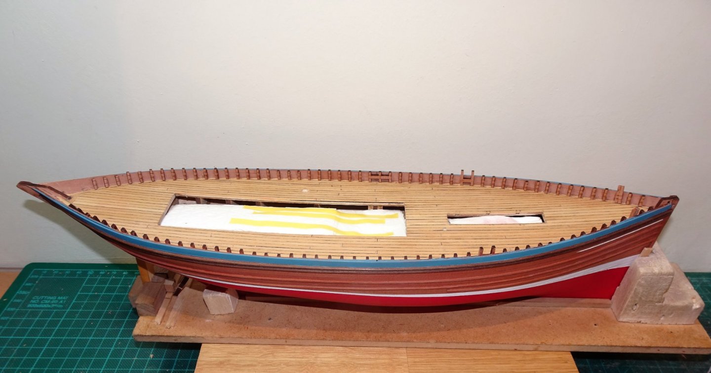
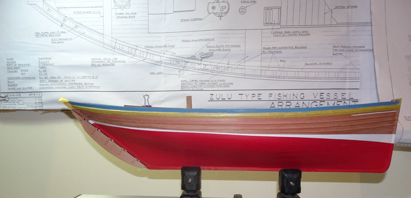
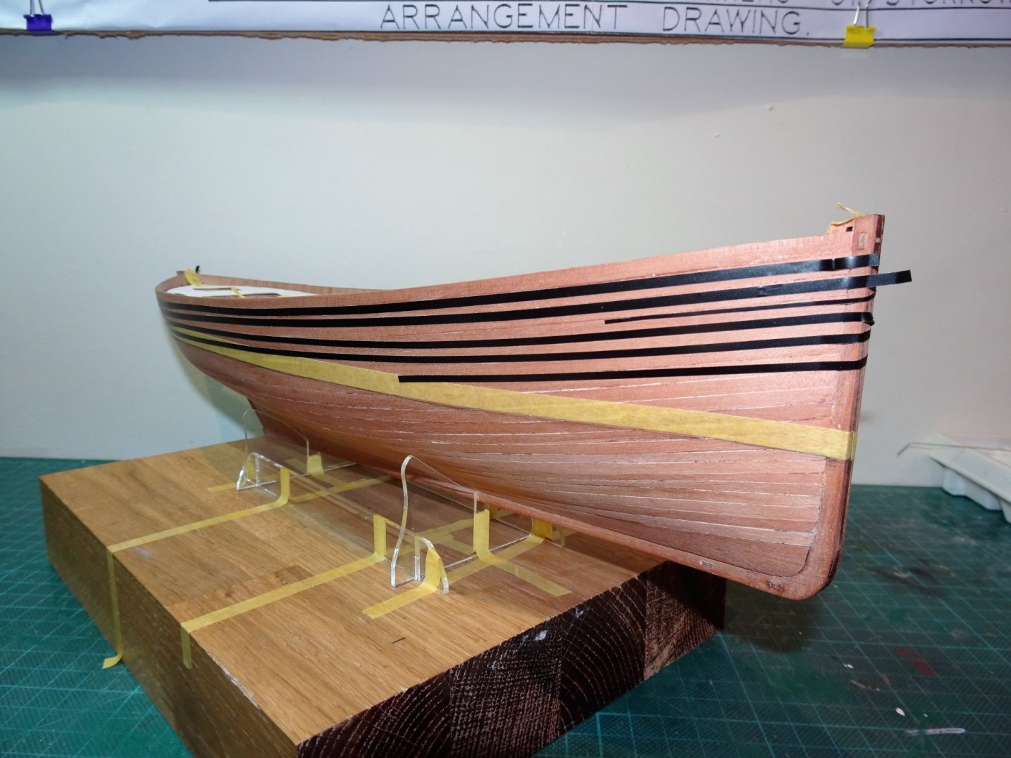
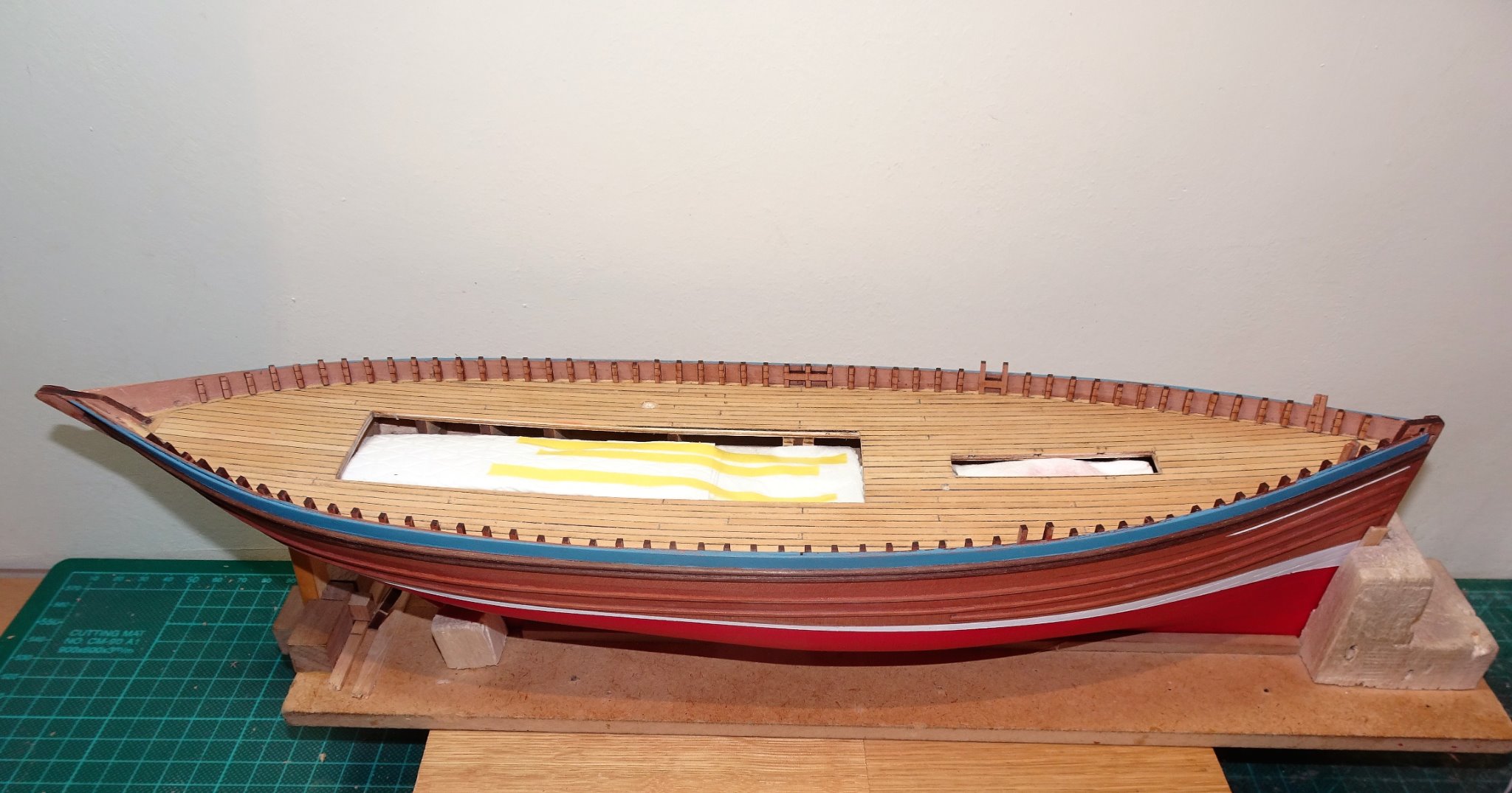
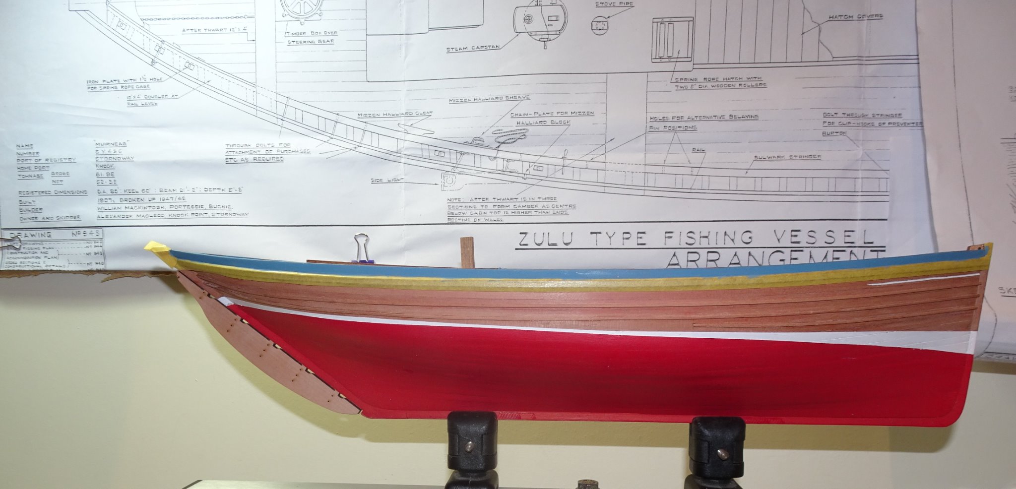
Post 14 Marking the waterline and getting some paint down This is probably the point to get some paint on the lower hull if for no other reason than to highlight any areas requiring attention. I will be using the scheme I used on the Fifie; red below the waterline with a white watercut, and varnish to the gunwale but where the top rail will be painted in a fetching shade of Blue, yet to be determined. In reality the hull would have been painted black but it’s a pity to cover all that rich natural Pearwood colour. In marking the waterline on my Fifie build I was singularly unsuccessful using the Amati Waterline marker but I resolved to try again having marked the relevant points at the stem, stern, and midships. 7493(2) The hull was placed on the provided stand, higher end forrad, which gives the necessary drag to the hull. It is then a case of tweaking the position of the hull in the stand until the marker pencil hits the marked spots on the hull. I took the precaution of taping the stand to a block of wood to reduce any tendency for movement. So far so good but any thoughts of one smooth sweep along the hull each side with the lines meeting at bow and stern were quickly dashed. 7516(2) After repeated applications where the damned thing seem to behave like a demented etch-a -sketch, I did achieve what looked like uniformity each side, sufficient anyway to tempt me to tape it up and lay down some paint. 7518(2) Unlike the Fifie, Muirneag is well endowed with rubbing strakes; I was interested to get an idea of how these came together on the hull and the relationship to the paint lines. 7503 To this end I used lining tape to represent the strips. 7501(2) Several more adjustments of the waterline tape followed this. A base coat laid down reveals areas that would benefit from a touch of filler. 7526(2) Four sand/fill/recoat sessions later and it’s time to see how the line looks. 7538(2) I am using Vallejo Flat red for the hull. 7530(2) Tamiya tape is used to mark the position of the white watercut. 7450(2) I used the kit proportions which compare very closely to the Underhill plans when converted from 1:24 to1:64. I have now been actively working on this construction for only four weeks, but it feels much longer. B.E. 30/09/20
.thumb.JPG.2f6530288a40e68316f542ca30a11c62.JPG)
.thumb.JPG.984e05aa3c2c497bf3897edb2adcf86f.JPG)
.thumb.JPG.24c1d56aa5f4e9141901bfc05c8794bb.JPG)
.thumb.JPG.644d6eb6a7dd816ac14ec75ce1949836.JPG)
.thumb.JPG.6f4158d6d19932dd2567989c6312e935.JPG)
.thumb.JPG.458c6f9c89bc6aa92158ece92e2340fa.JPG)
.thumb.JPG.12b24028b6f2b8b4f15af5386c62356e.JPG)
.thumb.JPG.b343620b678143b5952d32e0cf6a923d.JPG)
- 261 replies
-
- 11
-
-
- muirneag
- vanguard models
- (and 2 more)
-
Great result with your cutter Jason, I like the looks of her. 👍 B.E.
-
Fine work Glenn, your planking is a joy to behold. I was so grateful to Chuck for creating the makings to allow us to produce such a great model. Love your ‘mini me’ figure, I’m sure I would recognise you were our paths to ever cross.😉 B.E.
- 778 replies
-
- 2
-
-
- cheerful
- Syren Ship Model Company
- (and 1 more)
-
Post 13 Detailing the Fish hatch The Hatch depth on the Zulu kit is deeper than that of the Fifie so there is a little more scope for detailing. Altho’ not a lot will be seen once the nets are in place, it is an interesting exercise to fit it out as far as possible. The idea is to give the impression that there is more there than there actually is. 7435(2) The pierced boards of the hatch floor which allow the water to drain into the bilge are represented. 7438(2) Atop these the framing and boards of the Net platform. This is about as far as I can take it without a lot more chopping about which wouldn’t provide any greater visual advantage. 7442(2) The net boarding partitions and boards will now be removed until the poop deck carcase is finally fitted. Steering Box and Wheel I’ve also been test fitting the steering box and wheel. Note: the steering wheel stem is shown as pe part 29 in section 26 of the manual but is listed as part 27 in the parts lists, but it is easy to recognise. When I test fitted the wheel in place it struck me that it looked a little high above the box. It is in fact 6.5mm which scales to 16.4” I could not find an elevation shot of the wheel in place on either the kit plans or manual to give me a visual comparison. Underhill’s plans however, show the wheel at a scale 9.5” above the box which at 1:64 scales to 3.75mm. This puts the wheel at the level of the sliding roof of the companionway, which does seem more credible to me. 3554(2) Muirneag model as built by Gordon Williams and now held in the Museum Nan Eilean, Stornoway. This shot clearly shows the relative height of the wheel to the Companionway. 7457(2) The difference is demonstrated here. 7453 For the purpose of the exercise I used the kit Poop deck roof which won’t be used in the build. 7472 This photo depicts the wheel on a reduced length stem which suits my eye much better. 7484 7486 All this stuff will now be removed to prepare the hull for painting. B.E. 28/09/20
.thumb.JPG.e46c3de2c0d15e1a8df3584ae3a3e685.JPG)
.thumb.JPG.6629919474fd5e25c2942c06ea733acb.JPG)
.thumb.JPG.83356b32c1eaad5dd763372e72bcc260.JPG)
.thumb.JPG.b7e90fe62b5ce1e071a3338ea5096737.JPG)
.thumb.jpg.92c37d20ccc58103391533c35ba3d0d4.jpg)
- 261 replies
-
- 14
-
-
- muirneag
- vanguard models
- (and 2 more)
-
Cheers Glenn, there's a lot of fettling to do now I'm bashing things about a bit. 😄 B.E.
- 261 replies
-
- 2
-

-
-
- muirneag
- vanguard models
- (and 2 more)
-
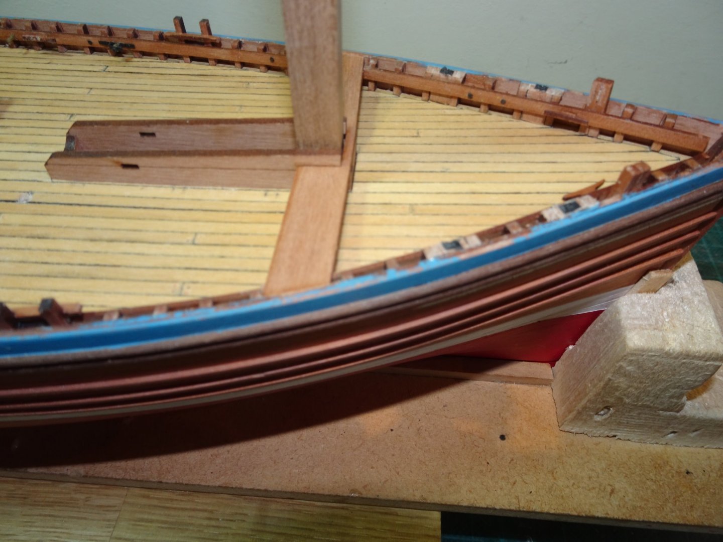
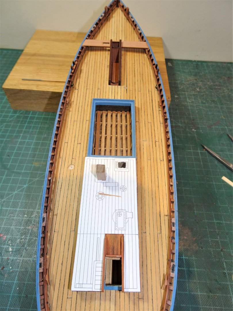
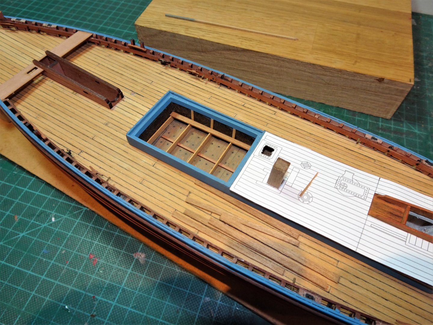
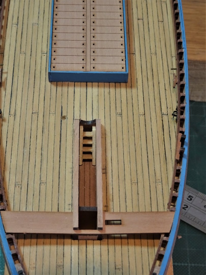
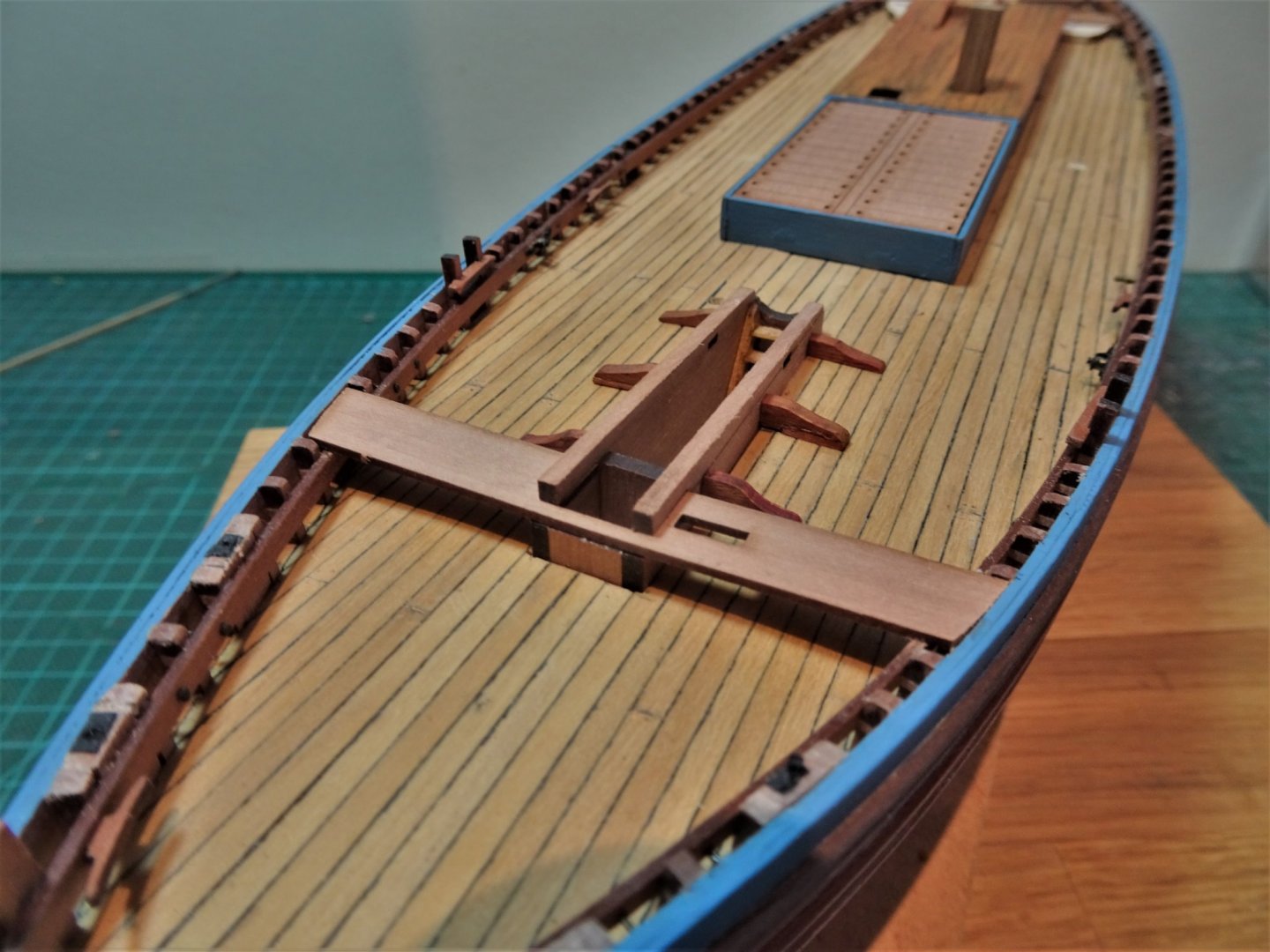
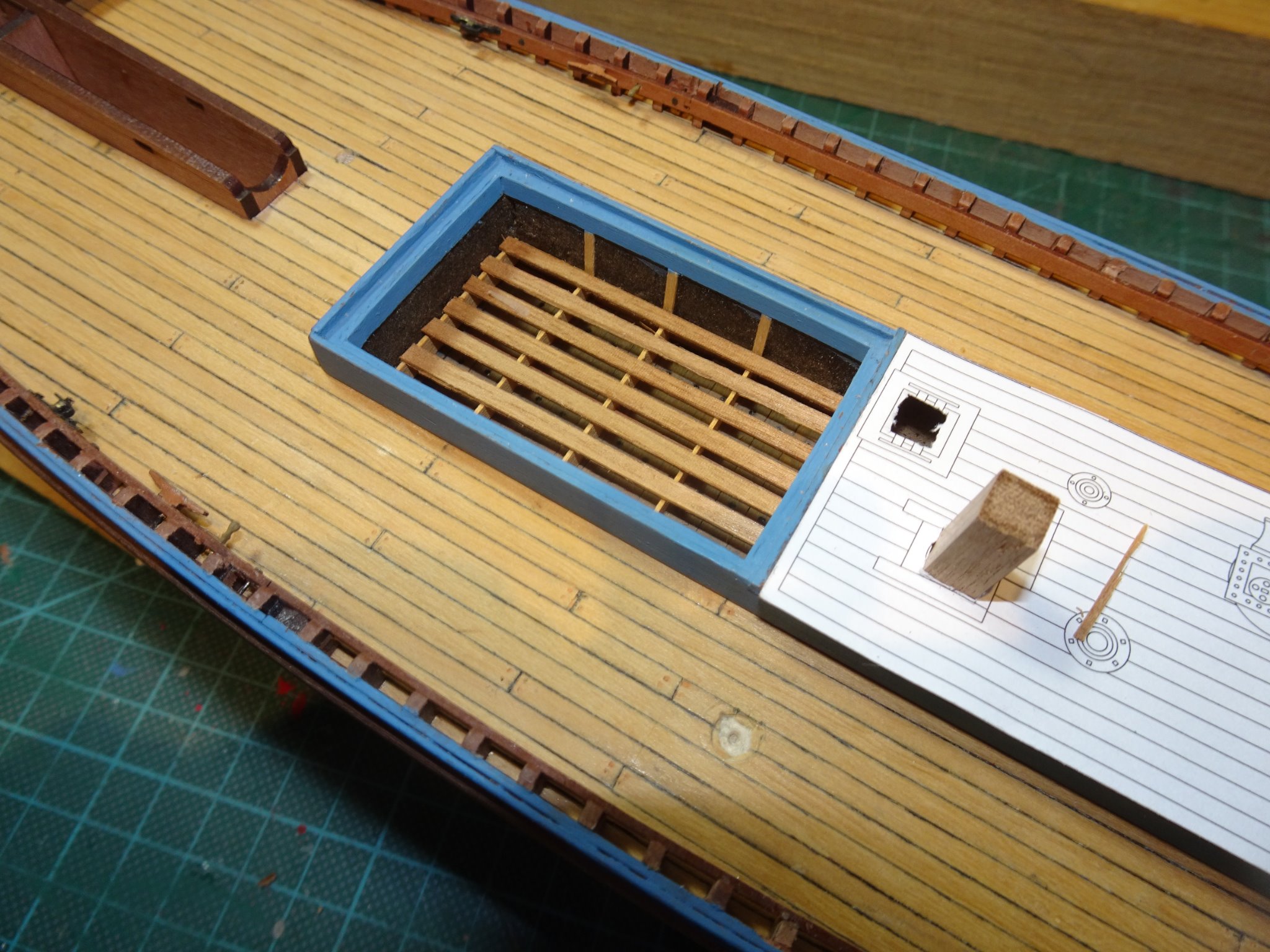
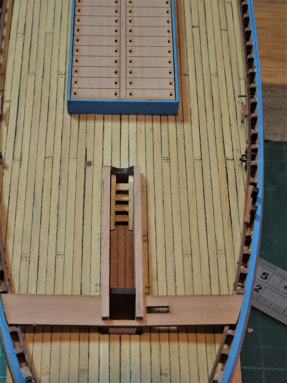
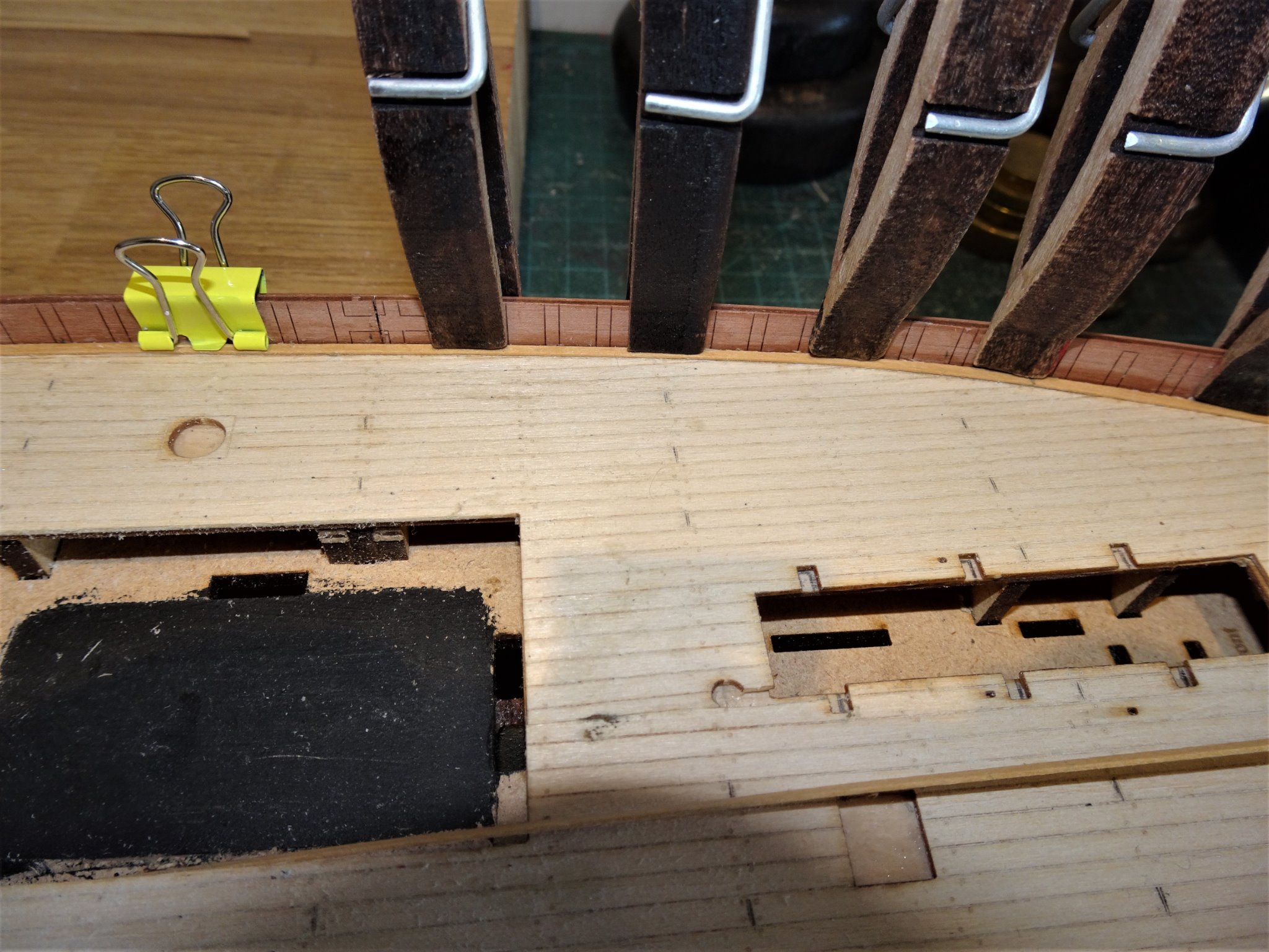
Post 12 Working out revised deck layout Before I proceed further with fettling the deck planking I need to work out the revised layout for Muirneag specific fittings. The Fore hatch has been planked over, and there is a slight shift in the positions of the coal bunker hatch, and the pump deck plate. 7420(2) The plan is a pretty good fit as an overlay. A major difference relates to the steering box. 7405(2) A replacement was scratched out of spare Pearwood strip. 7425(2) The box is smaller than that supplied with the kit and the aft thwart sits in a rebate in the box framing rather than part of a larger fitting called the rear bench pattern which combines with a knee at the stern post. 7427(2) One slight puzzlement, there is a rise in the deck towards the stern which throws the steering box out of level and will ultimately give a forward lean to the steering wheel. I will need to resolve this before final fitting. At this point I return to progress the Poop deck structure, the carcase of which I assembled earlier in the build. The Pearwood panels are now added but the aft panel which includes the Companionway, required some modification to suit Muirneag. 7402(2) On Muirneag the companionway is offset from the centre line to Starboard. In fact the whole Poop roof including the fish hatch boarding is to be replaced. 7407(2) Deck beams have been inserted to support the poop deck planking and carlings for the companionway sides. The lower deck cabin area has been planked. This is all necessary as I intend to have the Companionway open and a ladder installed leading down to the cabin area. 7418(2) An off-cut of thin box sheet is used to form a ‘false’ poop deck roof, over which the planking will be laid. This will bring the overall thickness up to that of the provided kit part. I could have used thicker individual planking, but a false deck makes it easier to mark and cut out for the fittings. I will next move onto fitting out the Fish hold. B.E 27/09/20
.thumb.JPG.00246e47d754495e8c3ba6d62b7dc85f.JPG)
.thumb.JPG.bd01f17498281953d926caa1597e90a9.JPG)
.thumb.JPG.d3fe9cf2fe77cf0099420520b77dcc84.JPG)
.thumb.JPG.d6ef51cca196d37b12905bbdcbd3f2e8.JPG)
.thumb.JPG.b3ee91a31df50f46fcb076ff37731d18.JPG)
.thumb.JPG.464e0ff6923d5a1bc73ea5415ebaf0c2.JPG)
.thumb.JPG.741e025f4efee7b5571ac798e94f6666.JPG)
- 261 replies
-
- 8
-
-
- muirneag
- vanguard models
- (and 2 more)
-
She is taking shape Richard, definitely a Fifie. 👍 I think you will end up with a good base for the second planking, pay special attention to the planks where they meet the stem and stern posts and fine them down until they lie flush with the posts. This is easier to do before you finally glue the posts in place, but you can use the posts to check progress. B.E.
- 49 replies
-
- 2
-
-
- Lady Eleanor
- Vanguard Models
- (and 1 more)
-
Thank you Tim, Yes I sanded it by hand, I used one of those foam sanding blocks (medium grade) which happens to be the width of the deck. It took a bit of time to get it down to less than 1mm thick, and I constantly checked the thickness as I went along. The Fifie deck is thinner but as it was a match to the Boxwood strip I was using I didn't need to use it. B.E.
- 261 replies
-
- 3
-
-
- muirneag
- vanguard models
- (and 2 more)
-
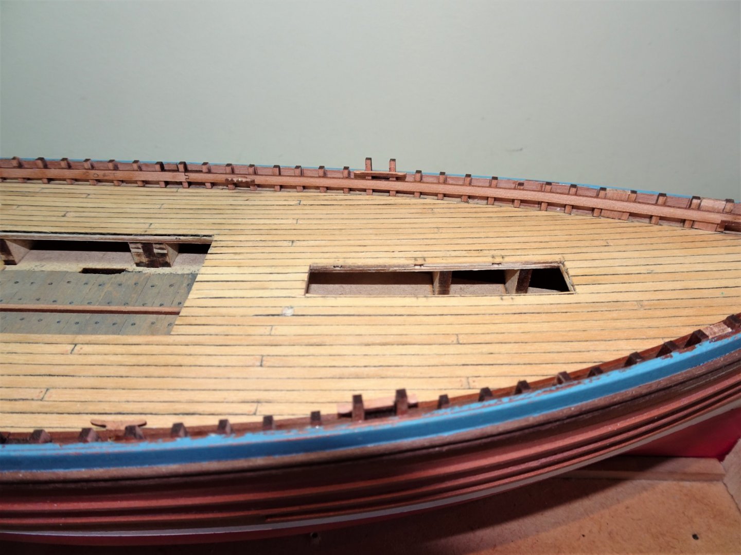
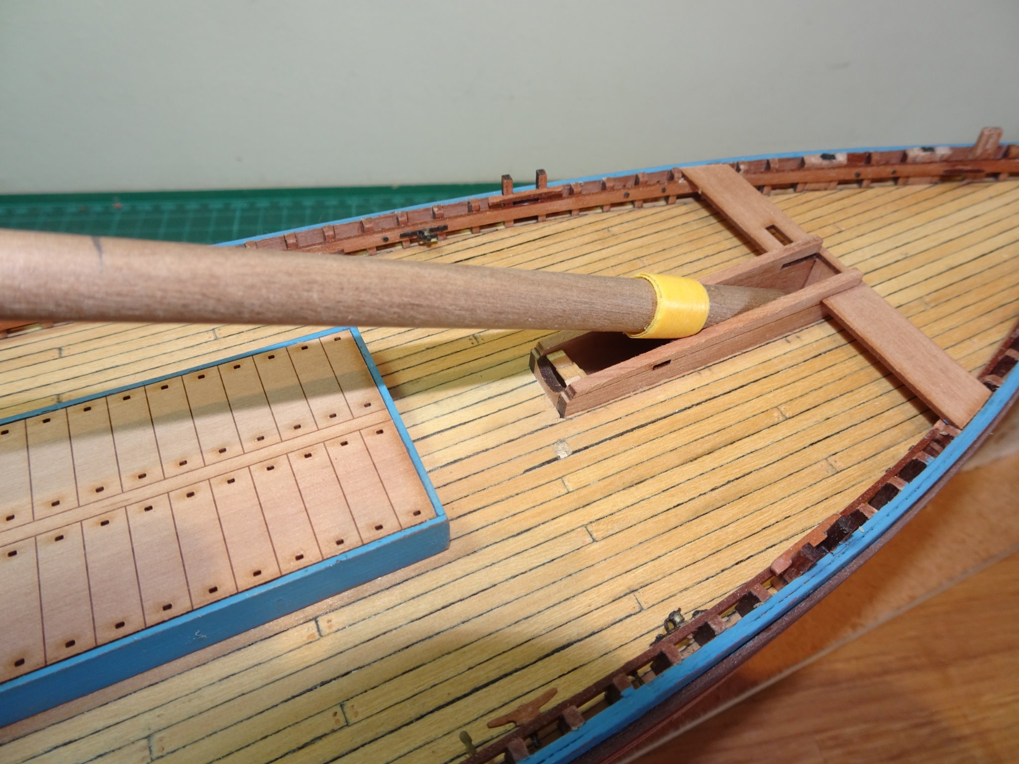
Thanks Guys, ..and Glenn, I think the scots are prepared to defend anything from anyone 😉 I hope so John, but the alternative would be to stand something big over the Fore Hatch which isn't there on Muirneag 🙄 Post 11 Getting down to decking I made the decision to sand down the back of the supplied deck to allow for the thickness of the Boxwood planking. 7334(2) The printed deck therefore becomes a second false deck with the advantage of having the printed layout to follow as a guide. The first task is to lay down the Margin plank. The proper way to do it would be to fit the timberheads and fit sections between them. However, to do it this way would impact on the provided timberhead pieces which were designed to sit on top of the deck, all individually sized and thoughtfully etched by Chris with the line of the Stringers. 7336 I simply can’t be tasked to remake all 98 of these tiny sections so I will follow the kit arrangement. Once the Bulwark stringers are fitted along the timberheads very little remains to be seen of either the timberheads or margin sections, so it’s not something to be overly concerned about at this scale. 7339(2) A fairly simple job to fit the margin, I am using 1.6mm wide strip which bends readily around the bulwark. Only at the stern end does the margin flare a little which is covered by a section of tapered 2.7mm strip. The planking begins each side of the centre line, and I have utilised in part the pre-marked butt shifts on the printed version. One edge of each plank is marked with a waterproof black marker to represent the caulking. I use a broad chisel Pilot marker pen. On this particular layout there is no joggling involved which simplifies things. 7345(2) Nearing completion. 7349(2) Completed but in need of a good scrape. 7358(2) A check to ensure that the Poop deck framing and Mast partners fit. At this point I have also beefed up the support stand, knocked up from bits and pieces but it works. The kit provided stand is a display stand not really suitable to work on the model. 7370(2) This particular hull shape is quite slippery and a stable support is necessary to hold it securely for work on the deck. B.E. 24/09/20
.thumb.JPG.87ec4ed355a18246ed0a79dd73691ab8.JPG)

.thumb.JPG.57912867c6fc2f1ac0cadb6390f92d70.JPG)
.thumb.JPG.3ec6be558c93b2dc34349eaaf1c98981.JPG)
.thumb.JPG.e38487c91f32c73aec65f03b5cac066b.JPG)
.thumb.JPG.c96af61d4cd3cfa096b6d6ae798d6a08.JPG)
.thumb.JPG.5aa57e7d9536aeaea9b29e6e5b8d2f98.JPG)
- 261 replies
-
- 13
-
-
- muirneag
- vanguard models
- (and 2 more)
.JPG.afd97e006f7e9225cda957b3e624aeed.JPG)
.JPG.89dc167c5911df0778056a75aed0154a.JPG)
.JPG.8de4a795b86c5d65c245bb3f103a2a94.JPG)
.JPG.d6cf6acf05dfaf8ee159143487d5bb68.JPG)
.JPG.78c7a70d23971e4755d447bcb2b29550.JPG)
.JPG.17e5283f02758014604c918aa30a640a.JPG)

.JPG.43d4c5ba431db2f1ba99da360b6d8117.JPG)
.JPG.196593ffc755a2cf31196d52f32d6337.JPG)


.JPG.ee54d99902af27cb2e625670b7477407.JPG)
.JPG.0a8c3d223a95cfdddc91e16a6dd6fb98.JPG)

.JPG.91c0b1c24366519f026b98d97bb27cf3.JPG)
.JPG.c9ef3126c4ee245de1db5b73937b8aac.JPG)


.JPG.311671f86d62dc178b9d2b48cebd1106.JPG)
.JPG.072495fbdcae123c05038d0dd6cffd48.JPG)
.JPG.61af7f2b9bf7c02679f64981e757e2a2.JPG)
.jpg.a05a876a5588663a823c1aac713cd53d.jpg)
.JPG.ee98a455ae44d085d40be73f7bc64a3e.JPG)
.JPG.aacd28915bb0eeb3fbae47bde126c2c3.JPG)
.JPG.770389417409c764c15667baea7fa58a.JPG)
.JPG.337cb247b0c55dae7575738a6616a613.JPG)
.JPG.ea62a7218781c152c6971b846494ded3.JPG)
.JPG.8945c67756a945026aa1e671e76b40e6.JPG)
.JPG.d81a5922308fb8cd7af1eb7f5b4651b1.JPG)
.JPG.a638b899374277251dd8c51915cb80cb.JPG)
.JPG.f3f68bcecff62fbc875f04c2f15fd5d3.JPG)
.JPG.bc79df7e95a6ab8ffe3a5f55fc565fc1.JPG)
.JPG.0f56717875d7e2391c2f968de5656ec2.JPG)
.JPG.13651182e5131a3be9b11fe9e6fab1e0.JPG)
.JPG.ccb21f8412670ed87a7f45ef656ba1bc.JPG)
.JPG.6e0e066e1f51b4c1b0c198d16e167986.JPG)
.JPG.ddae79981969d43318c524a06fe5d253.JPG)
.JPG.793ea7232fa78fa80525a89e3cd3bebb.JPG)
.JPG.fffbf8e231e3a26619e8393b42af9e91.JPG)
.JPG.ec35226701c5dbc1cf92319187679e39.JPG)
.JPG.5856dbc698bb71cdf9ea8e855437b2a3.JPG)
.JPG.b0bf7f8c6bd73d1d49fd247f6c432c74.JPG)
.JPG.b4f1b8206ecf1c39d3ac072cbc13c6d6.JPG)
.JPG.d8f18e848562bece1b9d5af4d2928d0c.JPG)
.JPG.59b69572c67b5efc79000db2dd0d0e79.JPG)
.JPG.0e9067c740633c433017a20f2783813d.JPG)
.JPG.6a35d13ac2b0b1f07640c6743421e8ea.JPG)
.JPG.4544db4e1e75b810dd35190151dedc08.JPG)
.JPG.7e6332c30b81dbf74b791fc4623c5c6a.JPG)

.JPG.6f9d353d4c1368cf501e282a47819e76.JPG)
.JPG.943a7727a6ea98abc3b1cfd72d2f788c.JPG)
.JPG.5d4e37b06f6c50dc5adc6b5f194b1aa1.JPG)
.JPG.f8556da012ca2b983f3c4fe951aaed13.JPG)
.JPG.d10f687ff863f325fbb3afa88ce3c30e.JPG)
.JPG.0caa313948f621569860d7fdf5c21edb.JPG)
.JPG.d30643fbd11f51e2e4e73c75c377c677.JPG)
.JPG.3e674b3688ce9adb7da4fa0021d40758.JPG)
.JPG.c339b6478c93c1e0c4a4fd8953875c1e.JPG)

.JPG.194fc2c5ac111a5bb46679c645f7800e.JPG)


.jpg.810ee944d1c6b93d73c293bb2cbdac84.jpg)
.JPG.768336614efdaf313a717b83886a8c31.JPG)
.JPG.8e3d2aafa00ef613bca5677b78b97886.JPG)
.JPG.7a661173196a5ad123d8cb59aa007b75.JPG)
.JPG.a8099ff2e5d8ffa536dab13cb8bf697e.JPG)
.JPG.56dc95e5b652a949dc0e4aeac5c9fd36.JPG)
.JPG.2c852c677f22f74d026a2ca7b30bc870.JPG)
.JPG.086e6e6456545ea34787d7eb261fa676.JPG)
.JPG.426d4af4a55dbf3a7717eebd760947aa.JPG)
.JPG.f802e9b7f8217152b5badb09c0446b01.JPG)
.JPG.1ee82c8ccaa42a6a5ac17fce482f9a87.JPG)
.JPG.0c1fbe6fe0f4da33bef9f0eb71672055.JPG)
.JPG.57230ae00050cbe0705fa62db40a2f88.JPG)
.JPG.39415f1cb47f843bf3c7724053047669.JPG)