
Chuck Seiler
-
Posts
1,878 -
Joined
-
Last visited
Content Type
Profiles
Forums
Gallery
Events
Everything posted by Chuck Seiler
-
Won't that stain the wood?
-
 I was hoping Louis da Fly, Druxey or AnobiumPunctatum would weigh in on this. They are more knowledgeable than I on this subject. "Collective noun" would be 'medieval ship'. As I understand it, NEF is an archaic French word for "ship" and encompasses the various northern European permutations of ships between the viking longship and knarr, and the cog, including roundships and hulcs. The nef that LdF is working on (and that I have on the back burner) is roughly based on the knarr (viking cargo ship) and was used in southern England (Cinque Ports) and northern France in the 12th thru early 14th centuries. This is not unusual, since the English nobility of that period were from Normandy and the Normans were transplanted Vikings. While no nefs have been found, there is much speculation based on artwork and wrecks of knarrs from a century or so before.
 -
HEY!!! You told me that alcohol was used for ungluing parts!!! Anywho, pulling up a chair and bowl of popcorn.
- 505 replies
-
- 6
-

-
- vanguard models
- Sphinx
- (and 1 more)
-
Doing a little math, LdF's nef is 14" at 1:75. At 1:96, that appears to pencil out at about 11". Does that sound about right?
-
Mark, Welcome to MSW and as mentioned in your WINCHELSEA build log, welcome to the Middle Ages.
-
I am not aware of plans of Winchelsea Nef in the National Archives...but then again there is alot I don't know. I know of the plans in the book NORMANNENSCHIFFE by Jochen von Furchs and the generic nef in the book by Zimmerman. Steven (Louie da Fly) is taking a different approach. I look forward to your build log. Welcome to the middle ages.
-
Mark, What are you using for plans?
-
Steven, It doesn't appear that your planks/strakes taper at the ends. Are they uniform width end to end or am I not seeing it properly?
-
Steven, You are progressing well. I had problems with the issue of transitioning the clinker into the rabbet at both ends of my cog. My efforts to transition from clinker to carvel did not work very well. I eventually did a version of Druxey's option 2.
-
Welcome!!!! Where are you from?
-
Greetings from Santee. Have you visited the San Diego Ship Modelers Guild yet?
-
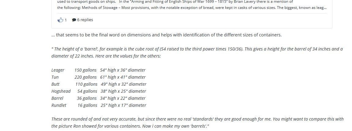
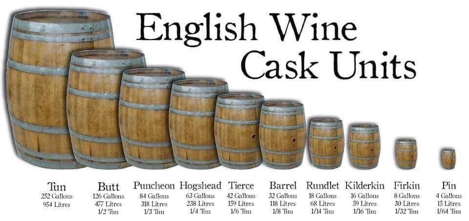
A couple references to barrels I have found over the years
-
I echo what others have said...it is a shame that you have lost interest since the model looks pretty good so far and you have made great progress. Sometimes taking a break from a model is the right thing to do, but be careful. If you put it on hold too long, you may not want to or be able to get back into it. I speak from experience.
-
I purchased some oversized Alaskan Yellow Cedar for my "Sea of Galilee" boat as well as some boxwood for a future nef. Both transactions were great and the wood is great as well. Very satisfied customer. Welcome aboard Joe.
-
For Beginners -- A Cautionary Tale
Chuck Seiler replied to ccoyle's topic in New member Introductions
You wouldn't be the first. I agree with Gregory, start with simpler kits. Build them for their own benefit but also as a work up to "Soleil". Check out the plans and instructions from time to time and if there are questions, work out the issues with the simpler models. Those are easier to deconstruct and rebuild. -
Divers Discover 2nd Century Military Ship off Egypt
Chuck Seiler replied to Ian_Grant's topic in Nautical/Naval History
The "Sea of Galilee Boat" used M+T joints and definitely reused wood. Not Egyptian. That was just the practice in the eastert Med area. -
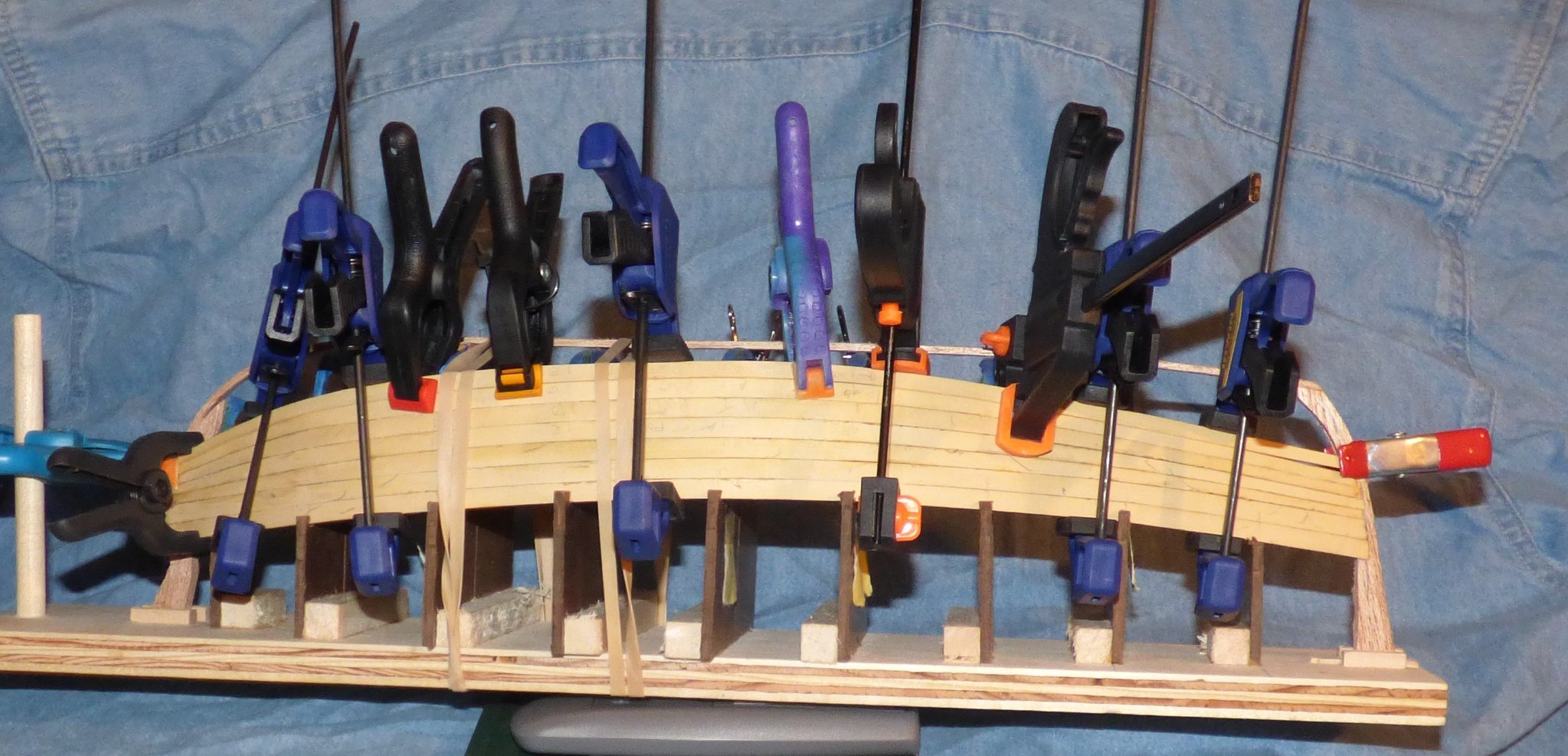
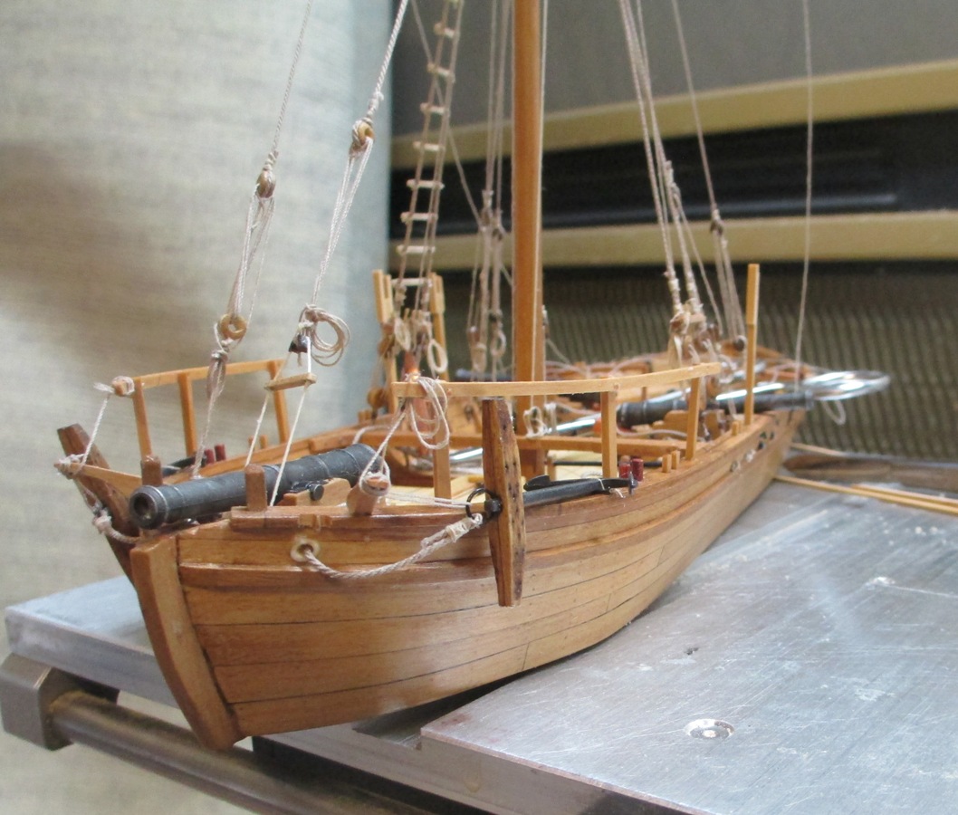
You can never have too many clamps...or rubber bands. After a basic bevel of some edges, I soaked the plank and clamped it into position to dry. I checked Kyle's build log to see what methods he used and planned accordingly. I have some larger clamps but wanted to keep them small if I could. So far so good. We'll see what happens when I unclamp. The result was not bad. A close examination shows the bevel needs to be touched up a little, but nothing dramatic. Tomorrow I will don magnification and get to work.


-
Lyle, So far so good with the dual tapers. I remeasured after strake 6 and I will have to make some modifications on my future tapers, but not much. I will use the old tapers for #7 and maybe #8, then re-calibrate.
-
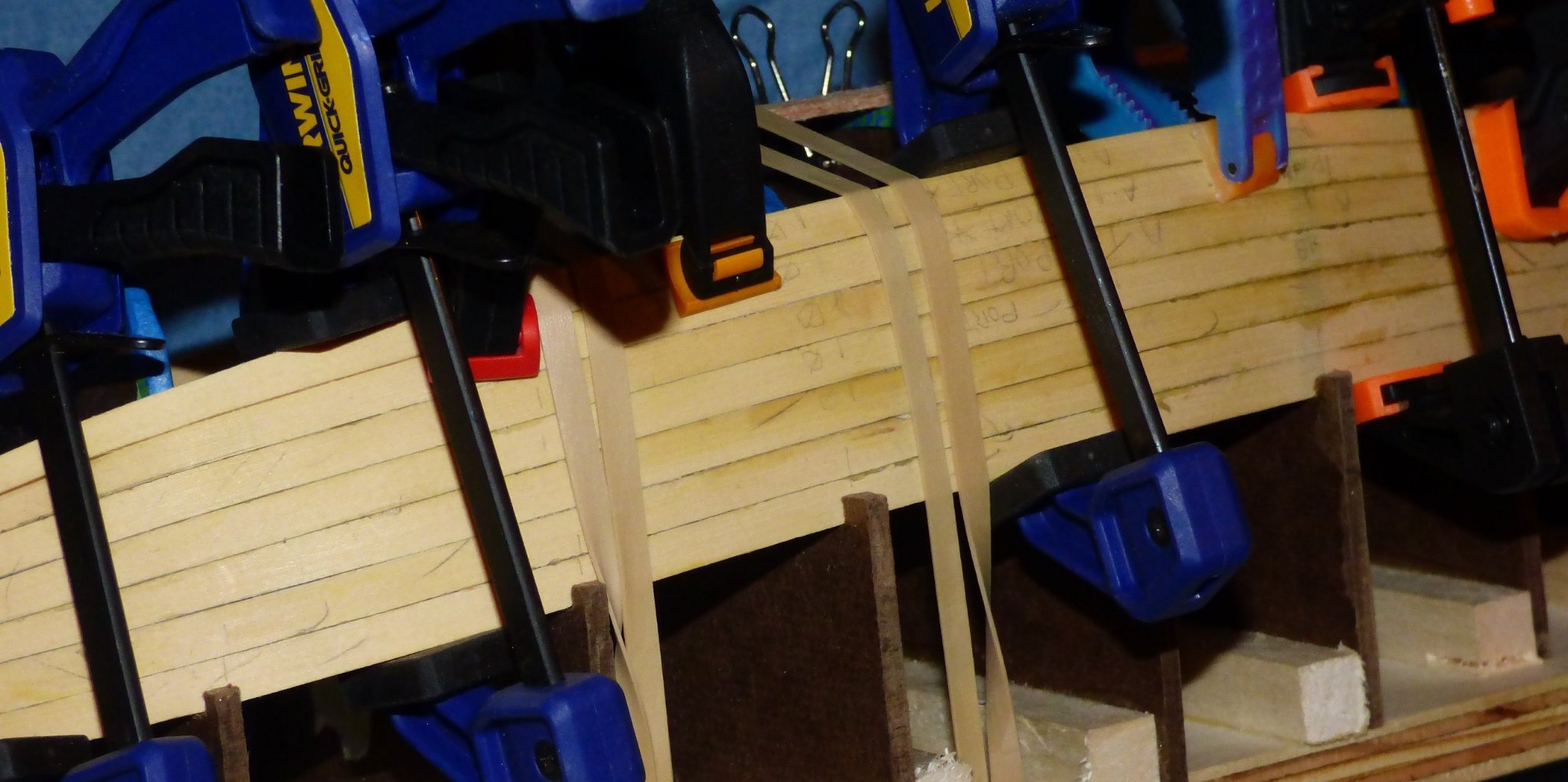
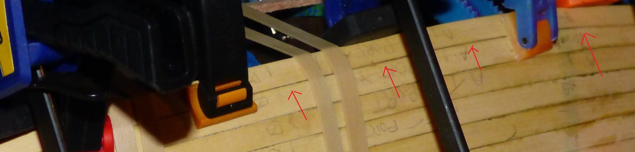
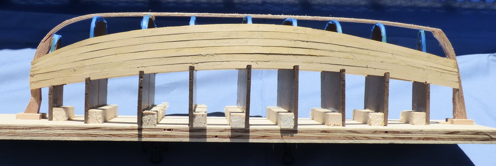
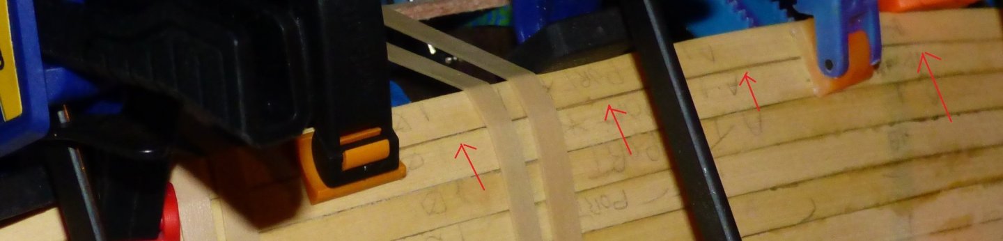
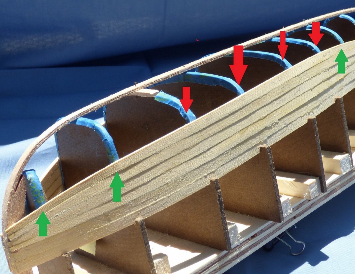
I have reached the turn of the bilge. Wow, this looks a lot worse in the full light of day than it does with inside lighting. I didn’t get the edge to edge alignment I was hoping for so some of the strakes stand out prouder than others. It should look fine once sanded down (and I should be rich and handsome too, but not holding my breath). There appears to be many gaps in the planking, but that is merely the shadows cast from the proud planks. If you compare my planking to Lyle’s, you see I have it tapered at both ends while the kit supplied wood is only tapered at one. Planking gets more interesting from here. Not only do I have to do a horizontal bends and vertical edge bend, I now need to start adding a twist. The green arrows show where no twist is required. The red arrows show where a twist is required to follow the turn of the bilge. THEN we untwist. That will be an interesting feat. The Alaskan Yellow Cedar is pliable enough, when wet, to do the vertical and horizontal bends with no problem. I am sure it will handle the twist as well. Going into a twist and back out should prove interesting. I need to check Lyle’s build log to see how his went. The other problem is that up until now, I was able to use a 4 inch bar clamp (several of them) to clamp the strake because the pressure is straight down. With the twist, I am unable to do that. Scott and Lyle both used CA glue so the old 5 fingered clamps were good enough. I must ruminate.

-
Weird. Hey, I am browsing here. I guess I will survive. Time for a beer.
-
Minor but vexing issue. In the last couple of weeks I have noticed I do not show up in the "Recently Browsed" section of posts I am looking at. I am able to "like", post and respond. I see other people, but not me. Additionally, I DO show up in "Who's online". What's up?