Landlubber Mike
-
Posts
4,548 -
Joined
-
Last visited
Content Type
Profiles
Forums
Gallery
Events
Everything posted by Landlubber Mike
-
 Looking forward to following this build Hamilton. I bet working at 1:53 will seem like you're working with gigantic parts after working at 1:100 On the keel, is it worth cutting out a new one? I cut out a new keel for my Unicorn using a scroll saw and it wasn't all that hard to do so. My keel was also warped, though not as bad as yours it sounds. It made me feel more comfortable working with flat stock rather than hoping that clamping and other steps ended up working.
- 69 replies
-
- 1
-

-
- fair rosamund
- occre
- (and 1 more)
-
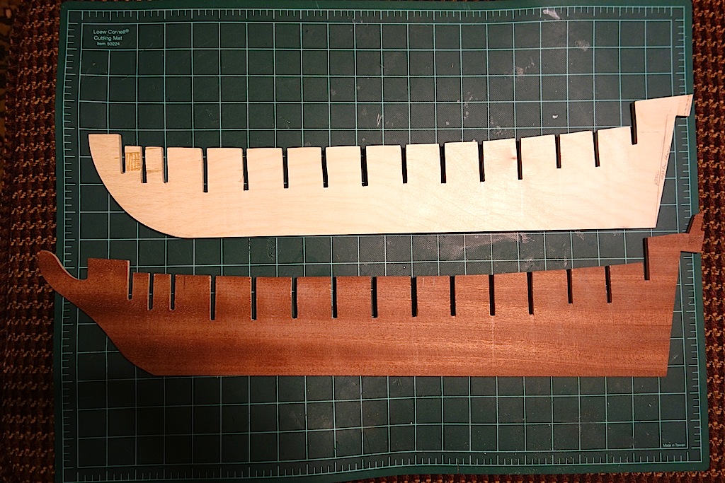
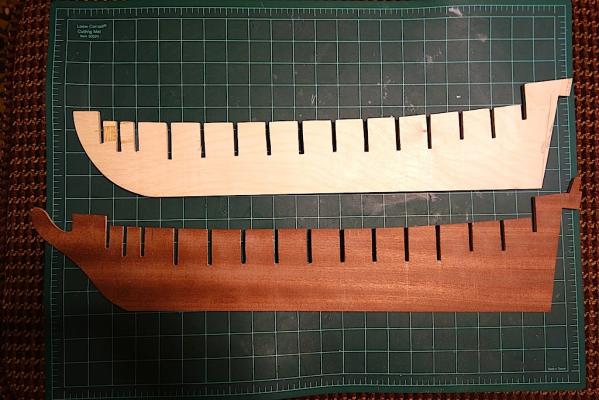
Quick update on where I am, as I actually started construction, rather than talking about it Since I'm planning on using pear for the exposed pieces of the stem, keel and stern post, I could either cut those sections off the kit keel, or cut out a new one that didn't include those areas. The choice was easy for me as the kit keel was warped. So, I went ahead and cut out the modified keel using my scroll saw, touching it up in areas with my new Byrnes disc sander which is an amazing machine. I can't seem to manually sand anything straight, and this tool really made work easy. I also added a 3mm x 1mm or so strip along the edge of the keel to add a pre-made recess for the rabbet. I wish I could take credit for it, but the idea came from Chuck's practicum on the Syren. Thanks Chuck! Next up is to start cutting out the stern post, keel and stem pieces. I'm taking a little time to learn how to use the Byrnes table saw, as I had a few issues from the beginning -- all user error of course, but a huge thank you to Jim Byrnes for calling me during yesterday's holiday to walk me through things and get me on the right track (talk about customer service!). So, just a little more practice and I should start cutting out the other pieces in the next day or two. I told Ian that I didn't want to have to change my alias on here to "9-Fingered Mike," so learning how to operate the saw safely is step 1.
-
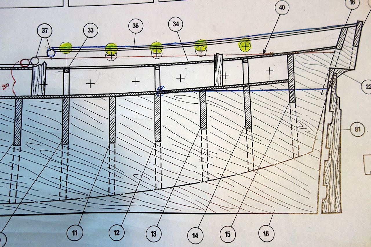
Here is a repost of what I posted on Ian's log in response to his thoughts on the revised lines of the quarterdeck and upperdeck which can be found here: http://modelshipworld.com/index.php?/topic/515-hms-unicorn-by-ianmajor-corel-scale-175-1748-to-1771/?p=202353 Looking at the Chapman plans versus the Corel plans, I think Ian is spot on as usual with respect to the line of the quarterdeck and upper deck. A few other differences I noticed from the Corel plans: 1. The height of the bulwark area of the quarterdeck section on the Corel plans gets narrower as you move forward. From Chapman, the height seems to stay the same. 2. The bottom decorative moulding at the end of the railing along the quarterdeck on Chapman seems to be a bit forward from where the Corel plans show it, as well as it should be a tad lower. 3. The quarterdeck on Chapman seems to end right at the top of the decorative moulding in (2) above. 4. The quarterdeck and the upper deck on Chapman seem to run parallel to one another. With these things in mind, I've modified the Corel plans as seen below: Hopefully the changes are fairly clear: 1. The top blue line at the quarterdeck bulkwark tops is the readjusted height of the bulwarks so the area stays at a consistent height (addressing observation #1 above). It worked out to a slight slope of 1.5-2mm in added height at the fore area. This is easily addressed on the model (I think!) because you can just use full, untapered planks to achieve the consistent height. 2. The red circle on the far left is roughly the new position of the decorative moulding (addressing observation #2). It's a tad lower, and the difference between the top of the moulding and the top of the upper deck below is about 30mm. 3. The modified upper deck line is marked as the blue lower line. It seems to intersect at about bulkhead 12. Working from the top of the moulding marked in red, I sketched the new quarterdeck line in red keeping a consistent 30mm height between the two decks. 4. The yellow circles are the portholes, which include an additional a fifth additional one at the front of the quarterdeck. Using the modified quarterdeck level and upper bulwark line, the portholes seem to open up fairly consistently with Chapman. Taking a step back and looking at the plans, I think the upperdeck and quarterdeck lines should sweep up a little higher at the stern. So, for the quarterdeck, I think I'm going to follow the line of the Corel plans starting around the area of the last upper deck gunport. I'll make a corresponding change to the upper deck line as well. I think if you really wanted to be consistent with Chapman, you probably would need to reduce the bulkhead height just above the upperdeck gunports. I thought about doing that, but that would take a lot more rejiggering of the plans, and I think I'm planning on changing them enough at this point. Changing the bulkheads is tricky business, so I'm trying to minimize them as much as possible.
-
Hi Ian, thanks very much for sharing your work on this. Looking at the Chapman plans versus the Corel plans, I think you're spot on as usual with respect to the line of the quarterdeck and upper deck. A few other differences I noticed from the Corel plans: 1. The height of the bulwark area of the quarterdeck section on the Corel plans gets narrower as you move forward. From Chapman, the height seems to stay the same. 2. The bottom decorative moulding at the end of the railing along the quarterdeck on Chapman seems to be a bit forward from where the Corel plans show it, as well as it should be a tad lower. 3. The quarterdeck on Chapman seems to end right at the top of the decorative moulding in (2) above. 4. The quarterdeck and the upper deck on Chapman seem to run parallel to one another. With these things in mind, I've modified the Corel plans as seen below: Hopefully the changes are fairly clear: 1. The top blue line at the quarterdeck bulkwark tops is the readjusted height of the bulwarks so the area stays at a consistent height (addressing observation #1 above). It worked out to a slight slope of 1.5-2mm in added height at the fore area. This is easily addressed on the model (I think!) because you can just use full, untapered planks to achieve the consistent height. 2. The red circle on the far left is roughly the new position of the decorative moulding (addressing observation #2). It's a tad lower, and the difference between the top of the moulding and the top of the upper deck below is about 30mm. 3. The modified upper deck line is marked as the blue lower line. It seems to intersect at about bulkhead 12. Working from the top of the moulding marked in red, I sketched the new quarterdeck line in red keeping a consistent 30mm height between the two decks. 4. The yellow circles are the portholes, which include an additional a fifth additional one at the front of the quarterdeck. Using the modified quarterdeck level and upper bulwark line, the portholes seem to open up fairly consistently with Chapman. Taking a step back and looking at the plans, I think the upperdeck and quarterdeck lines should sweep up a little higher at the stern. So, for the quarterdeck, I think I'm going to follow the line of the Corel plans starting around the area of the last upper deck gunport. I'll make a corresponding change to the upper deck line as well. I think if you really wanted to be consistent with Chapman, you probably would need to reduce the bulkhead height just above the upperdeck gunports. I thought about doing that, but that would take a lot more rejiggering of the plans, and I think I'm planning on changing them enough at this point. Changing the bulkheads is tricky business, so I'm trying to minimize them as much as possible. If you don't mind, I think I'm going to add this to my build log just for completeness. Hope I didn't hijack your log too much

-
Ian, great work as usual. The cosmetic changes to details like the steps and arches really improve your build. I have to say, I don't know that I would have the guts to redo my work like you have been doing John, the transom came out very nicely. Just out of curiosity, how did you do the letter for the ship name? They came out really well, with perfect spacing and color matching.
-
Hi Ulises, thanks very much for sharing the results of your finish experiment. I'm actually thinking of building the Charles Morgan whaler with a weathered appearance, and recently placed an order for Weather-It and a few other weathering applications. I was worried that adding a finish could affect the results of the application, and it seems like that might the case unfortunately Thanks for sharing, and wonderful build!
- 786 replies
-
- 1
-
-
- Royal Louis
- Finished
- (and 1 more)
-
Joe, I would echo what others have said about Jeff's wood being well worth the wait. I haven't worked with it yet, but the quality seems to be night and day relative to the Caldercraft kit wood. If the walnut in your kit is anything like the walnut I had in my Badger kit, the frustration you'll find in working with it will likely make you kick yourself for not upgrading it. I found that it wasn't just the wood strips that were very prone to splintering - the pre-cut pieces are made up of walnut ply, and a lot of them not only chipped on me, but I even had some pretty much disintegrate on me after I cut them out. The good thing is that Caldercraft usually adds extras for the pre-cut pieces and wood strips, but even then I was forced to settle on things that were not very good.
- 302 replies
-
- 1
-
-
- granado
- caldercraft
- (and 1 more)
-
The most silent disk sander
Landlubber Mike replied to Mike Y's topic in Modeling tools and Workshop Equipment
The sander is about 2/3 the size of the table saw or so. Maybe think about modifying a rotary tool like a dremel or proxxon to serve as a sander if you don't need too much precision? -
The most silent disk sander
Landlubber Mike replied to Mike Y's topic in Modeling tools and Workshop Equipment
I echo the Byrnes disc sander. Used mine the first time the other day, and was really impressed. It's built like a tank, and runs fairly quiet. What is noisy is running a shop vac to the sander. I have a Fein shop vac, and while it's on the quieter side, it's still fairly noisy when everything is running together. That being said, it's not like I'm running power tools and the shop vac for hours on end at a time. -
Nice present (and even nicer wife), and happy birthday!
- 302 replies
-
- 1
-
-
- granado
- caldercraft
- (and 1 more)
-
Hi Hamilton, I logged onto MSW this morning to see the thumbnails on the home page of what was a gorgeous model recently added to the completed gallery. I was really happy to see that it was your Blandford. Really amazing work, especially at that scale. I think I've gone permanently cross-eyed from working at 1:64 - I can't imagine what you went through at 1:100 The sweep ports in particular are a really nice touch to your model. Gardiner's new Frigate book has a picture on the cover of a model with the sweep ports and oars, and yours looks every bit as good as the one on the book's cover. Thanks very much for adding back the pictures to your log. Your approach gives me a lot to work with when it comes to scratching the stern on my Unicorn. What's next for you? I see you have the Hannah SIB kit - have you started it? I've been working on mine in fits and starts over the last year or so, and finished the hull a few months ago. I am complicating things for myself by trying to add the "sea" to the bottle, which is very hard to do given the tiny opening of the bottle. Congratulations again, and thanks very much for sharing your journey!
-
Looking forward to this build. The LGV is a gorgeous ship. I have the Ancre monographs which are really well done. I wish I had the experience to tackle it
-
Thanks very much Hamilton, no worries if it is too much trouble. I'm mostly interested in how you handled the structural issues. The Unicorn was around 1748-1771, so if I remember correctly the details about the Blandford, the Blandford preceded the Unicorn. I have the AOTS books on the Blandford and the Pandora (which came after the Unicorn), which have been helpful to me in thinking about some of the modifications). Since the Unicorn fell in between both ships period wise, I figure I should be ok
-
Hi Vince, thanks again for sharing your build. I've been learning a lot from you, so thank you. The bleach method for the deck planking looks really great. Seems to be a cheaper alternative if you want to use the deck planks that come with the kit rather than buy holly or the like. Just out of curiosity, are you using straight bleach or are you diluting it? Do you rinse the planks after they have soaked in the bleach? Any concern that the bleach may corrode the wood over time?
-
Really amazing work Hamilton. I'm in the early stages of modifying the Corel Unicorn, and your log details of your trials and tribulations have really helped open my eyes to some of the pitfalls I should expect Your approach to the stern galleries worked out very nicely. I think I'm going to do something very similar. Can I ask you to repost the pictures on how you scratched the transom? That's the one area that I've been struggling with, and it would be of great help to see your pictures if you still have them. I think the post is on page 13 or 14 of your log. Thank so much!
-
Hi Ian, thank you very much for the heads up on this. I wonder if the issue was from the bulkheads extending too low? Not sure if they fixed that issue on the newer kits, as mine seem to sit higher. I'm going to plan on taking Chuck's approach towards building in the rabbet by adding a thin strip of wood along the edges of the keel that is maybe 3mm wide, so that it builds in a rebate for the rabbet on the 5mm keel. That will give me a little extra room so that I don't run into the issues you ran into. On the keel, do you remember if you sanded down the keel at the bearding line to the edge? That might help alleviate some of the issues you experienced at the keel and rudder. It's good to know, just in case I run into similar problems. For your bulkheads, do you remember whether the tops of the bulkheads were at the height of the keel (and just above at the crown of the bulkhead to account for the curve in the decks)? My bulkheads seem to fit a bit higher, which means I might run into problems like you did at the keel if I lower them. Hope you had fun with the grandkids
-
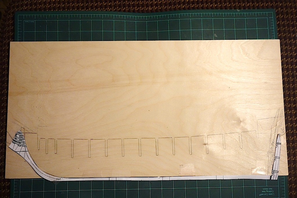
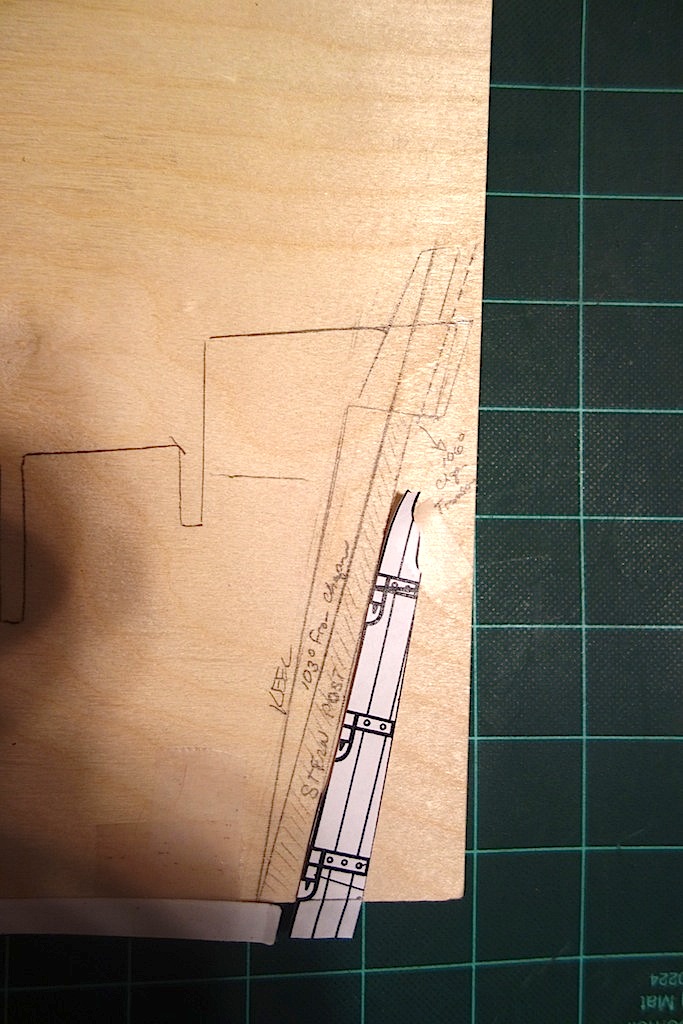
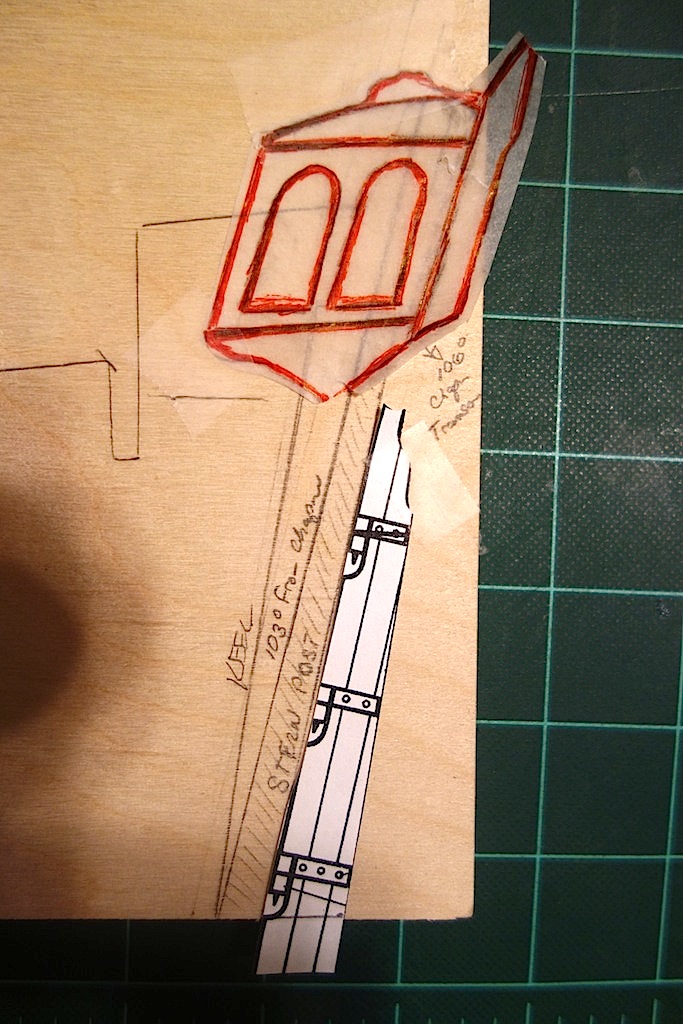
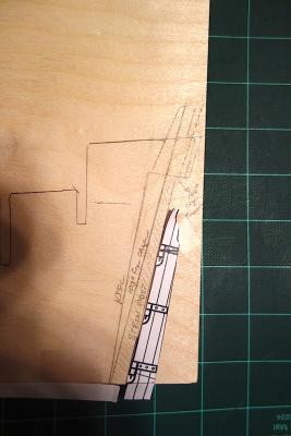
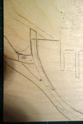
For what it's worth, I finally finished sketching out the template for the keel. It's a bit hard to see in the picture, but the white paper templates are the stem, keel and rudder. Because the keel is a relatively straight line, I used the bottom of the plywood piece for the keel line which is why the paper template is hanging off the edge (rather than trying to cut it on the scroll saw and have to true up such a long line) I struggled a bit with deciding whether to shorten the keel, which would pull the stern galleries closer to the last gunport as per the Chapman plans. I decided against it, as it would really throw the lines off the hull I think, particular if it compressed the area of the last three bulkheads. So instead I decided to not shorten the keel, but rather modify the angle of the fore edge of the stern post, and add a stern post. From my measurements, it looks like the fore edge of the stern post needed to be pushed out another 4 degrees to 103 degrees per Chapman. I then added a stern post, which gradually tapers to a narrower width as you go up the post. The rake of the transom in Chapman came to 106% per my measurements, so you can see how that pushed out the line. The dotted line is where the front edge of the transom should end up. I built out the keel a bit more to the right of the dotted line to help serve as a stern extension, which would define the foremost edge of the curved transom. Here is the picture above with a tracing of the stern gallery from the kit's plans. The windows will need to be spaced and oriented a bit differently, but you can see with the modifications how the gallery sits more forward over the stern post and rudder, where in the kit plans, it hangs way aft from them. I also started sketching out the bow section a bit. There are probably three changes I'm making to note here. First, I think a ship like this would only have one set of gammoning. Second, from the Chapman plans and other similar ships like the Pandora, the stem comes up and supports the bowspirit (roughly sketched). Third, I think the kit's bow is missing the gammoning knee, which I sketched in as the part above the gammoning piece that contains the gammoning slot. The gammoning knee has a hole for the main stay collar (not sketched in) - the kit on the other hand has you add a 5mm x 5mm piece at the top of the stem at which to take the main stay collar. Not sure if the kit is correct or not, but I'm going to go with adding a gammoning knee piece to the stem. It's a bit late for me to break out the scroll saw tonight, so I'm going to sleep on the sketch and hopefully start making sawdust later this week


-
Hi John, I haven't really figured out how I'm going to put the transom together yet. What i might do is start with a thin sheet of basswood or plywood to get the template down in the shape I want, then add better wood over it (either with planks or just solid pieces). I'm also considering your approach of building up to a thicker piece, and then sanding in the contours, versus adding frames or stern extension pieces onto which to mount the transom. The general framing of the stern is really driving me nuts right now. I'm planning to not include the flag locker, which means the top halves of bulkheads 16 and 17 need to be removed. In doing so, I lose out on the end frames on which to attach the hull planking at the quarterdeck. I suppose I could always do what other kits do and create a pseudo gunport pattern for the hull area at the quarterdeck, which would be attached to very thin frames at the two bulkheads which ultimately would be removed.
-
Wow, gorgeous work!
-
Maple is a great wood - nice upgrade over tanganyika. I bought the pins from Hobbylinc.com. I really liked using them as they have a longer, thinner profile than push pins, with a relatively sharp point. http://www.hobbylinc.com/htm/mid/mid587.htm
- 302 replies
-
- 1
-
-
- granado
- caldercraft
- (and 1 more)
-
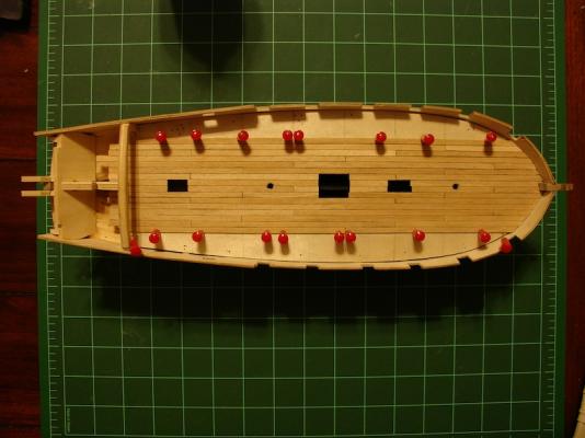
Looks great Joe! Glad the gunports are cooperating. Just out of curiosity, did Caldercraft switch to maple for the decks from tanganyika? My Badger had tanganyika, which was a nice wood, but some of the strips were warped and/or not very straight. For what it's worth, I used these red pins that have a very thin needle and a small profile to keep my planks straight on the deck
- 302 replies
-
- 3
-
-
- granado
- caldercraft
- (and 1 more)
-
Hi John, thanks for your thoughts. Thinking a little more on it, I think you and Ian are right that maybe I should just remove bulkhead 17, tilt the transom, and add the stern post to the end of the keel. Attempting to move both the stern post and the transom/galleries further inwards to get the galleries closer to the last gun ports probably will cause me more problems than they are worth. As Ian pointed out, (1) removing bulkhead 17, (2) tilting and curving the transom and (3) widening the stern galleries should get me very close to the Chapman plans without messing with bulkhead 16 and the stern counter. Your approach to the transom sounds like it can actually work very well. That's an ingenious idea to keep things in place, yet build in the curve and extra rake to the transom. How are you thinking about doing the windows? Are you going to paint the modified bulkhead 17 black and fit clear windows against it?
-
Thanks Ian. I was originally intending to reduce the length of the keel, and add the stern post to it (rather than just add a stern post to the end of the current keel). That would just push the stern further out from the last gunport. But, I might need to reassess given that my keel is actually shorter than the keel diagram on at least one of the plans (it's longer as to the other plans). Keeping bulkhead 17 around as a backup plan does make sense now that you mention it. Too bad it is plywood, as it would be nice to contour it with a little curve. I could always cut a new one out of basswood or walnut to serve as the template for the shape I want, and then plank over it.
-
Hi Ian, that's really interesting. I always wondered what those scales referred to. I went through my resources last night to research tillers, and unfortunately I didn't come across anything that mentioned for what reasons the tiller would be on the quarterdeck as opposed to below. It looks like the tiller set up takes up quite a bit of room though - I wonder if it really was feasible (or safe) for the quarterdeck to have all that armament on it if the tiller was there? Perhaps descendants of the Lyme class had modified sterns to move the tiller below the quarterdeck? I'm not really sure. The gentleman with the 1:48 scratch build added the quarterdeck tiller to his build, so you're probably right He did add 8 cannons on the quarterdeck forward of the tiller assembly (along with 26 cannons on the upper deck). Thankfully this is something that I have a little more time to think about. If you did go that route, I think it would add a nice touch as it essentially is one of the few ways to expose the inner workings of the ship. I also spent a couple of hours thinking about how the stern modification would need to be accomplished. I really feel woefully in the dark on this as I only have one model under my belt. The Badger and Pegasus kits use gunport patterns and stern extensions to create the curve of the transom and the stern counter. Chuck's Syren kit has you add "L" shaped stern framing pieces to frame the transom and stern counter. Given the curves and modifications, this is fairly complicated for me, and pretty much a critical thing to get right. I'm thinking that I might have to go the framing route and just guess at contours as the Corel kit doesn't use gunport patterns. To move the transom forward, have it slightly curved, and change its rake, I've come to the conclusion that bulkhead 17 has to go and that extensions or framing will have to be built on the after-face of bulkhead 16. I'm thinking too that the stern counter has to be moved forward as well. The kit has you add the stern counter template to what essentially is the after-face of the stern post. In looking at Chapman however, it looks like the bottom of the stern counter should start at the fore face of the stern post. This probably means moving bulkhead 16 forward and/or modifying it a bit so that the curve of the planking to the stern counter is relatively smooth. That modification makes me very nervous as there are a lot of curves at that area. I've also been planning ahead for the rabbets - Chuck has a very interesting approach on the Syren build. Rather than cut the rabbet onto keel only, he adds to the edges of the keel a thin strip of material than is less wide than the keel piece so that you end up with a built-in rebate. From there, he chisels the keel piece a bit to ensure a smooth transition into the rebate. Seems a lot easier to do that than cut a straight consistent groove along the keel - one of those "wow, why didn't I think of that" moments Thanks Chuck!
-
I marked up a copy of the external hull plans to show everything that appears to be different from Chapman. I'll try and get a good resolution image up tonight.