Landlubber Mike
-
Posts
4,544 -
Joined
-
Last visited
Content Type
Profiles
Forums
Gallery
Events
Everything posted by Landlubber Mike
-
 Nice Ian, I really appreciate you sharing your research That sounds like a good way to approach the belaying plan. Ah, too bad about the lateen rigged mizen That would have been a fun detail on the ship.
 -
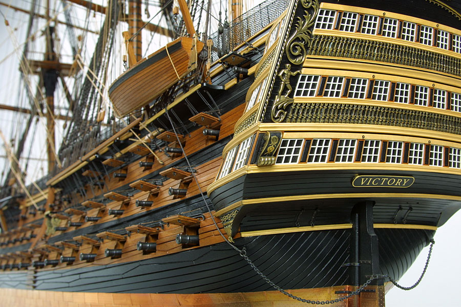
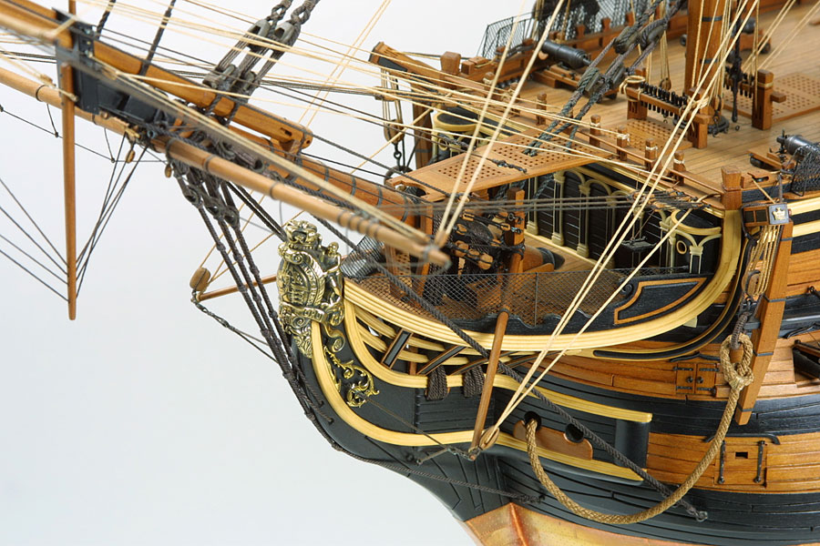
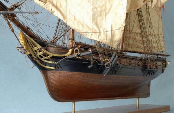
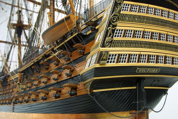
Hi Martin, thanks so much for looking in. I love your Fly build - it's coming along very nicely. I love the look of the boxwood against the holly. My Unicorn will be on the lighter side (though, a bit darker with pear against boxwood). For the Pegasus, I'm thinking of something a little more darker, like SLR0461 from the NMM: This Le Cyclope from Bernard Frolich is another color tone that I like (among other things!), which is borrowed from here: http://modelisme.arsenal.free.fr/artdumodelisme/galeriegb.html This is another model that is closer to what I'm thinking of doing with Pegasus - a Victory using pear, maple (I imagine for the decks) and ebony which is borrowed from the link below. I particularly like the use of boxwood accents and gilded/burnished decorative pieces against the ebony: http://www.shipmodels.com.ua/eng/models/elite/victori/index.htm


-
Really gorgeous work Toni. I'll be curious to see what wood/finish choices you decide on, as I'm going through the same considerations on my Pegasus.
-
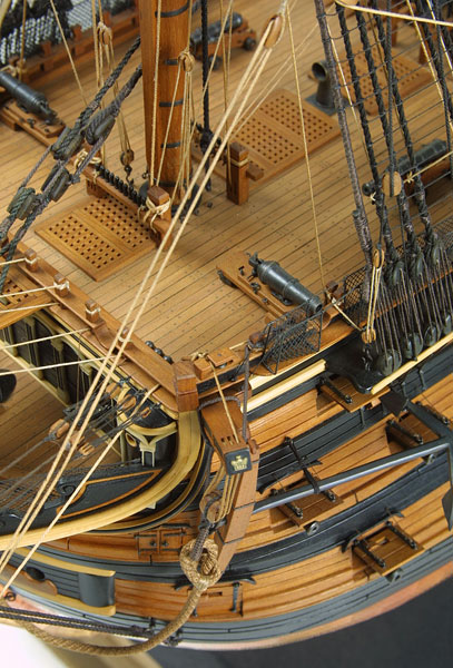
Last night I took the first step in removing the keel, bulkheads and other parts from the 5mm MDF boards. The MDF is very strong, and my initial impression is that there is zero warp in the pieces. No pictures at the moment, but the parts are laser cut very nicely - perfect symmetry and very clean cuts, and it looks like everything is fitting together like a glove. It's a great way to start the kit by not having to worry about warping and symmetry issues. As I was looking at the plans last night, I started thinking about what, if any, of the kit wood I would like to replace. Like my Unicorn/Lyme, I want to avoid paint as much as possible. The Unicorn/Lyme is going to be mostly in pear (oiled for natural look and dyed black for the black areas), and boxwood for the deck, accents and carvings/detail pieces -- pretty much almost a complete kit bash. I'm hoping to use more of the kit wood with the Pegasus as it seems to be a very accurate, but we'll see as I progress along the build. For the Pegasus, I'm thinking of taking a different approach from the Unicorn of having more of a darker hue to the overall build. I still plan on dying/staining the bulwark planking and cannon carriages red, and hopefully the kit pieces take the ebony dye/stain well for the black areas. I'm also thinking of using boxwood for the rails and headrails and other ochre pieces, rather than painting them ochre. Instead, for the detail decorations, I'll either paint them to match the boxwood or try a more gilded or burnished look. Also, I might try working with holly for the stern windows and for what I expect to be scratched small boats as I really prefer to avoid white paint - to me, even using a dull white looks too garish against a model that is mostly oiled and/or stained, though maybe an ivory paint or a light wash over a dull white paint would look ok. That leaves me with the deck planking, hull planking, and masts. I'm thinking about going with maple for the decks, and a darker wood like walnut for the hull planking and things like the hatch coamings. I'm not sure about the masts yet - I could go boxwood to tie with the boxwood accents, or go dark like walnut (or use walnut stain on wood like the kit dowels). I would love to just be able to use tung oil on the walnut kit pieces (I loved the look of the oiled walnut on my Badger), but the colors of the kit's walnut range from almost blonde with the stem and rudder, to a darker brown with the planking strips, to a more burgundy hue with the thin walnut ply pieces, to all over the place with what I think are walnut dowels. I'll probably talk to Jeff at Hobbymill for suggestions, but I might have to replace much of the walnut just for pure consistency of color. If anyone has any wood or color suggestions, i would love to hear them
-
Eamonn, thanks very much! I think you're right that having the plans framed would be a nice touch. Martin, thanks very much for looking in. The plans are really fantastic, aren't they? I need to find more friends like you as that would be a really nice present!
-
Hi Spyglass, thanks for that. I'm going to think a little more on which way I want the bolts to sit. Maybe it is just safer to install the nut in the keel... I just took a look at the packaging for my "bolts" - they are called "machine screws" even though they look like your typical bolt
-
Really nice work Eamonn. Very crisp, clean build. Your planking is fantastic!
- 1,039 replies
-
- 1
-

-
- ballahoo
- caldercraft
- (and 2 more)
-
Nice Joe Just out of curiosity, what are you planning on using the walnut for? I am thinking that I want a darker, more wood-grained look to my Pegasus, and thought about upgrading the kit's walnut to Jeff's walnut
-
Thanks, sorry, I jumped the gun On the nuts getting loose issue, I was thinking that once I epoxied the nuts in, I would fit in some wood on top of the nut on either side of the screw path so that the nut can't get loose in the vertical plane. Then, with the side pieces of scrap wood, the nut would be more secure on the horizontal plane. I'm going to have to think about this a little more. I imagine that the screw ends pointing out can be a nuisance over time, but maybe that's all the more reason to attach the model to a temporary baseboard at an earlier stage than I did with my Badger (lap modeling isn't very safe for your build as I can attest). I need to see how long the screws are relative to the pedestals and with respect to a future display board. You probably need to drill a deeper/wider countersink hole from the bottom of the final display baseboard, but that shouldn't cause too many problems. I appreciate the permanence issue of inserting the screw into the hull, but I wonder what the chance is of ever needing to take it out?
-
Thank you! That makes a lot of sense. Do you see any downside of fixing the head of the screw into the keel, rather than the nut?
-
Thanks very much Ian. The Pegasus plans took about two weeks from my order date to arrive, so hopefully I'll have the Lyme plans sometime next week. I'll let you know how they look. If they are half as nice as the Pegasus plans, I'll be very happy. Spyglass, thanks for those tips. I used epoxy once before on some gardening equipment, and while it does the job, it's pretty nasty smelling stuff. Definitely a job you want to do outdoors. I don't think I'll need much more than a dot of the stuff on each end given it's holding power, but it's so thick that I worry about getting too much into the slot and it fouling up the threads. Good tip on keeping the thread moving. That's also a very good tip on filing down the ends of the screws. The machine screws I'm using have a very fine thread, so starting them into the nut requires precise alignment. I should also start working on the cradle/baseboard, that's a great idea. On my Badger, I used the kit cradle to store the ship when I was on the hull planking and other early stages of the build, and then installed it onto its permanent display board once I was onto the rigging stage. Then, I just glued the display board onto the display case baseboard when the model was done. This time I'm planning on doing something a little different for the final display, where the pedestals will sit directly on the display case baseboard since I think that should have a cleaner look. I'll still need to come up with a temporary build board in the meantime - I might use the kit cradle, or I might just cut out a piece of MDF for additional stability. Two quick questions if you don't mind: 1. I saw that you added blocks on either side of the nuts. Is that to help lock in lateral stability? The nuts are slightly wider than the 5mm keel, so I might have to file the corners down a bit so that the sides are flush with the keel. 2. Rather than installing the nuts into the keel, have you ever considered installing the screw/bolt/rod into the keel, essentially reversing the set up with the head of the screw in the keel slot? I think that approach would avoid two problems: (1) epoxy getting into the threads of the nut, as you don't really care about the threads at the head of the screw; and (2) it might be a little easier to thread the nut onto the screw, rather than thread the screw into a nut that is hidden within the keel. You can also epoxy the length of the screw in the keel for added stability. The downsides of that approach are: (1) to install the screw, you will likely need to create a slot into the keel along the full length of the screw (not so big a deal as the slot will be hidden by the planking and the pedestal brackets); and (2) you will be stuck working on the model with the screw ends sticking out of the bottom of the keel. I'm not sure that I've seen this approach used before, which tells me there is a bigger pitfall out there that I'm not seeing. Thanks in advance!
-
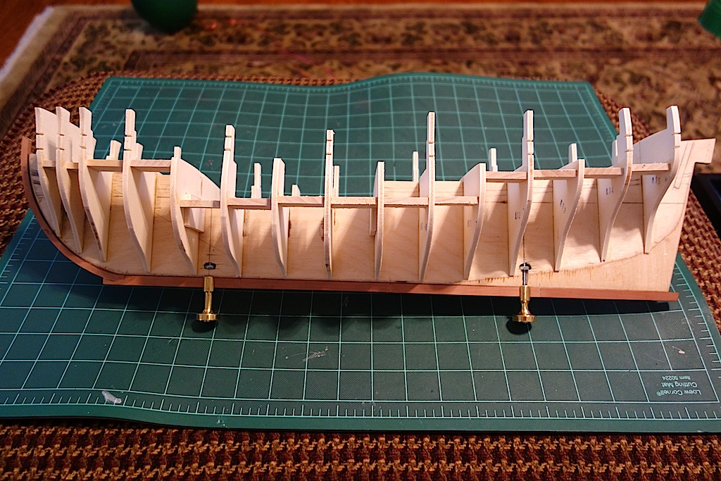
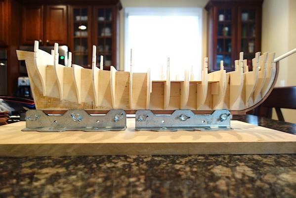
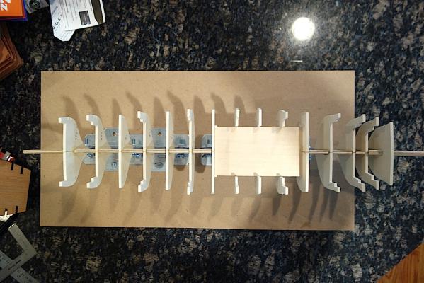
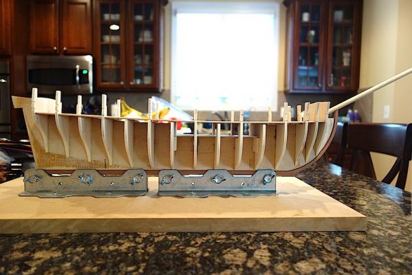
I made some more progress this weekend by installing braces between the bulkheads and the mounting nuts for the display pedestals. It's interesting how much prep work goes into a build in the early stages just to ensure a good base for things, when one just wants to jump to putting the model together when the kit box is open. First, I added braces of 5mm plywood in between the bulkheads. I found that the bulkheads had a bit of flex to them at the ends, but now with the braces, there is no flex whatsoever (except at the very tops that frame the bulwarks for the fore deck and quarterdeck). Not sure if this is just wishful thinking, but the hull feels like it's built like a tank now. I also worked on installing the mounting nuts for the pedestals. Given that the waterline is not parallel to the keel bottom (thanks Spyglass!), I'm using different sized pedestals -- 1 3/8" for the front and 1 1/8" for the back from Model Expo (each with 3/16" slots that work nicely with the 5mm keel). Rather than using the wood screws that came with the pedestals, I'm using 2-inch long #6 machine screws and nuts. On my Badger I used the wood screws, but found it very hard to get the keel mounted perfectly, and there is a very slight lean that I could never fully fix. So, hopefully in mounting the the nuts parallel to the baseboard, I wont run into that problem on this build. After drawing the waterline, I drew the screw lines perpendicular to that line. Then I drew a line line perpendicular to the screw lines where the nut will sit. With the different heights of the pedestals yet the same 2" screw, you can see that the rear nut will sit lower on the keel that the front nut. Then it was a matter of drilling and filing a flat seat for the nut, and then drilling the hole from the bottom of the keel up into the keel for the screw. I started with a pilot hole using a no-walk bit, then worked my way up about a half dozen or so bits until I reached the diameter of the machine screw. The Hobbymill pear drilled very cleanly - the wood really machines very well. The plywood didn't hold up so well, particularly for the rear pedestal where the screw line ran through the thinner section under the bearding line and the plywood flaked off. But, since all this is covered it anyway, it should be fine. Next step will be the epoxy the nuts in, but since I hate working with that nasty stuff, I think I'm going to do it the same time I epoxy the nuts into my Pegasus build. I'm waiting on the NMM plans of the Lyme before making a decision on which ship to build. So, I probably won't have many updates until then, as the next major section to tackle will be to frame the stern and install slots for the masts in the keel to help lock them in. The sterns should be very similar, but it's probably better that I wait until the Lyme plans arrive. In the meantime, I'll plan to try out the various stains and dyes that I have, to figure out which to go with. I have some dyes and stains from General Finishes in both black and reds, as well as Fieblings black shoe leather dye. Hopefully these give me the look that I'm going for.
-
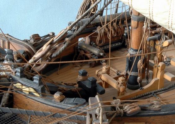
Mkmossop, I did the Flemish coils for my gun rigging on my Badger using the technique of coiling the line around a pin on top of painters tape, but thought they looked a little too neat. For the remaining coils, I decided to have coils that looked more like yours. What I did was again use painters tape, this time wrapping the line around a pin, putting diluted PVA on the line, and in one motion, pull the pin and put another piece of painters tape on top -- essentially, as you pull the pin the line loosens and gets messy, but by putting the second piece of painters tape on top, you help freeze the coil in position. I then wait a while for the glue to dry, remove the tape and you have your coil. Now, the coils come out randomly that way, and some you'll end up throwing out, but to me I preferred the result to the Flemish coils.
-
Ha! I can take some if you want -- my wife might let me come back on this board though
-
You're right Spyglass - I looked at the plans and the stern does drop a bit. I must have mis-measured a while back.
-
Haven't cut the holes for the rods. You're right that they would have been a lot easier to fit before adding the bulkheads, but I think I should be able to manage. I needed to order the pedestals, plus, I wanted to get a little further along in figuring out where the stern will end up in order to properly center/position the pedestals. Wish me luck
-
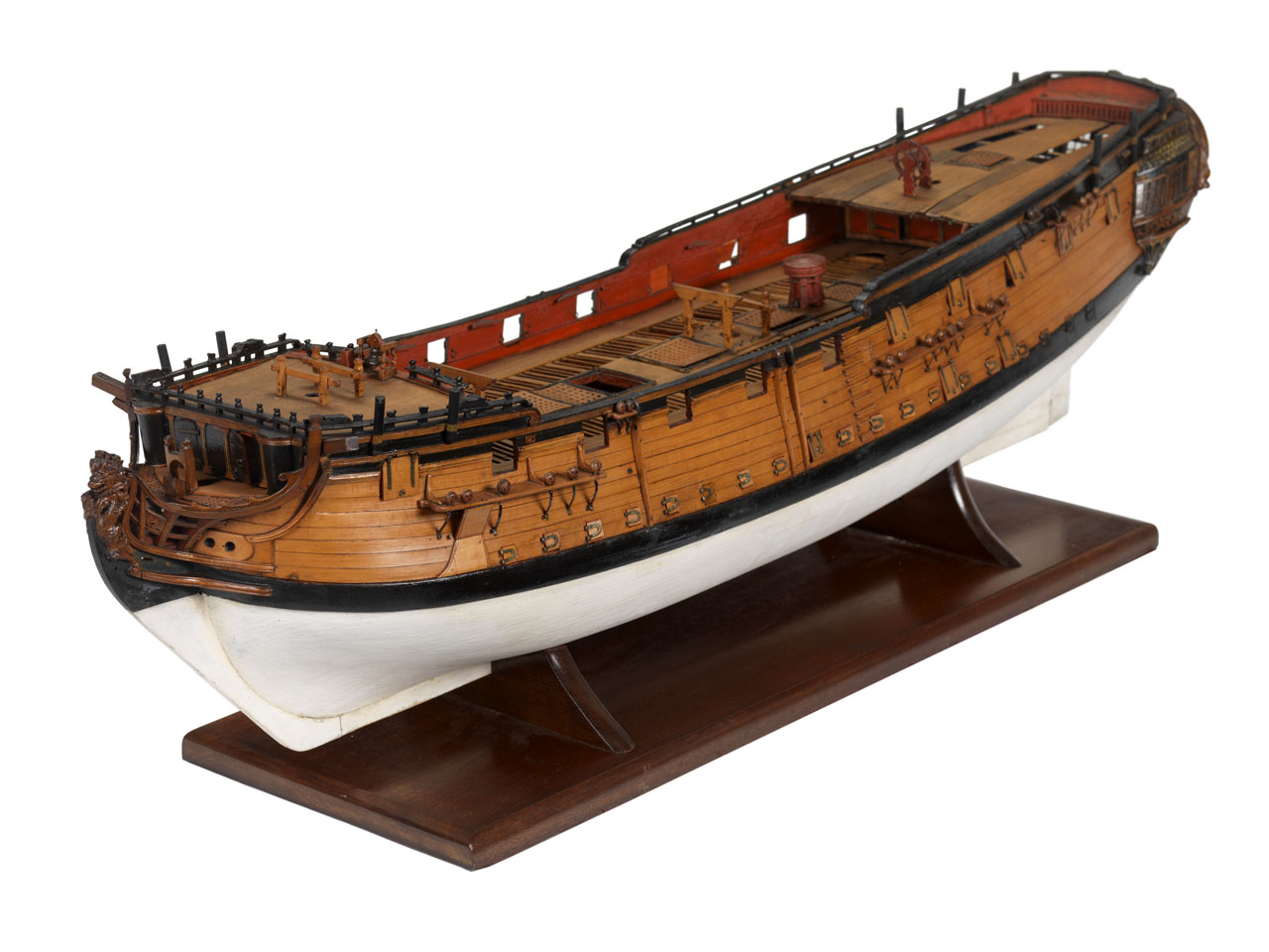
I received my set of pedestals in the mail recently, so I'm going to fix nuts inside the keel rather than use the wood screws that come with the kit. i had a question though - in looking at the kit plans and plans for other similar ships, it looks like the keel is relatively parallel to the waterline. Is that typical? The Badger's keel dropped lower as you approached the stern, so I used a taller pedestal for the fore area and a shorter pedestal in the aft area. Given that the keel seems to be more parallel, It looks like I'll need to use pedestals that are the same height. It looks like from Spyglass' Pegasus pictures that he used pedestals of a similar height, so it's very likely that the Pegasus keel is parallel to the waterline as well. Second question - I plan on using boxwood for the decks. Should I use boxwood for the false lower deck? It seems like I could get away using different wood given that the lower deck will be mostly covered with gratings and the ladder for the companionways (and I might cover the waist with small boats), but I figured I would ask. I haven't yet made a decision on whether to build the model as the Unicorn or the Lyme. I ordered the Lyme plans from the NMM, so once I see the transom and other decorations, I can figure out which looks nicer, and probably more importantly, which I am more likely to successfully pull off From what I can tell looking at the Chapman plans against the NMM Lyme online plans, aside from the beakhead versus rounded bow, and some minor cosmetic things like railings and numbers of portholes, the ships are pretty much identical.
-
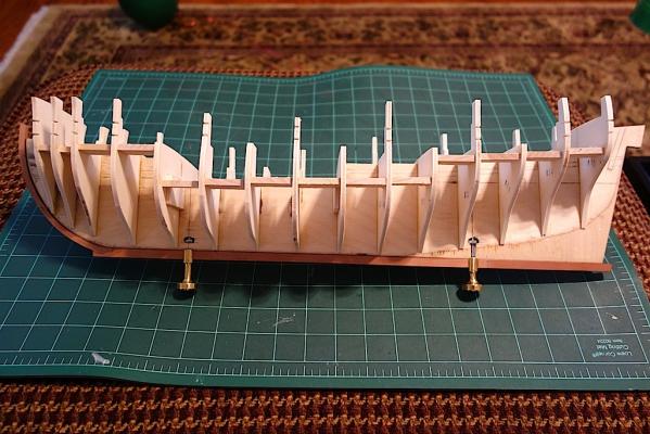
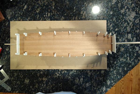
I made a little more progress the last few days, installing the remainder of the first 15 bulkheads. Unlike the Badger where I pretty much glued them all to the keel in probably the span of an hour, I took my time on the Unicorn as there was more play with the keel that I cut, and I didn't appreciate the importance of squaring things with the Badger So, I glued one bulkhead at a time, using squares, levels, etc., and letting the glue dry at least an hour before moving on. Probably a little on the cautious side, but I figured it's more important to get it right and square. Since I plan to frame the stern, I won't be using bulkhead 17, at least where the kit would have you add it. The kit has you add it to the very end of the stern, and then attach the cast metal stern to it. Instead, I'm going to sit bulkhead 17 right up against the after face of bulkhead 16, and cut notches into it to seat the stern frame extensions. This should work well because bulkhead 17 is the lateral width of the stern (not including the transom), so by seating the outer extensions into the two sides of the bulkhead, I should be able to frame the end of the ship for both the transom and the planking for the sides of the ship. Here are some pictures, including some with the false lower deck and upper deck dry fitted. Despite the plans being all over the place and not consistent with the kit parts, the kits parts fit very well together. Next I plan to add some bulkhead supports to maintain the squareness of the bulkheads, especially since the plywood used for the bulkheads is a bit on the flexible side.
-
Thanks Ian for that info. Interestingly, I came up with a height of 30mm between the two decks as well but by the lazy way in readjusting items on the Corel plans to fit Chapman and then measuring the distance. Amazing that I got as close as I did. That step up is very nice!
-
Looks great Jason. That's also what I did on my Badger. Kester tells you how it really should be done, but I don't know that I could have done that as more and more deck details started getting in the way. One approach that Hubert recommended on his website was to connect the belayed points first, then run the lines to where they should start. That seems like a good way to avoid all the difficulties with belaying lines when the deck starts filling up, but I wonder how easy it is to attach the lines to blocks, etc. and get the proper tension. It seems like you would be just substituting one difficult task with another.
-
Hi John, It's a bit late here, but I saw your post and wanted to respond. Are you thinking of raising the quarterdeck at the stern so that the line of the upper deck/great cabin would flow into the stern windows? I was thinking of taking a different approach outlined in the link below where the front section of the quarterdeck would be raised, and the aft end at the same level, or perhaps, slightly lowered: http://modelshipworld.com/index.php?/topic/6223-hms-unicorn-by-landlubber-mike-corel-scale-175-1748-1771/?p=202411 Here is a link to Ian's log where he sketched out a similar modification: http://modelshipworld.com/index.php?/topic/515-hms-unicorn-by-ianmajor-corel-scale-175-1748-to-1771/?p=202353 I think the difference, at least in my sketch, is that I planned on the windows being lower on the transom. I was thinking about reducing the height of the windows like you did, but rather than block out the lower section of the windows, I would just essentially cut that bottom section off and move the windows down into the blocked out section (hopefully that makes sense). The alternative would be to take Ian's approach on blocking out the top of the windows, which you can see here: http://modelshipworld.com/index.php?/topic/515-hms-unicorn-by-ianmajor-corel-scale-175-1748-to-1771/?p=205888 I hate to suggest this, but would it be easier (or at least more appropriate) to move the windows down, rather than try to reorient the quarterdeck? You would lose the band on the counter with the name of the ship, but you could always move that down as well for a 2-step counter like in your painting above?
-
Very cool - this book seems to have been written using the same framework as Robert Gardiner's "The Sailing Frigate" that was published last year, which I really enjoyed. This book on sloops is about double the length of the frigate book Any good details for those of us building sloops, like the Swan class line of ships?
-
Take a look at the Proxxon DB250. I used it on my Badger and really liked it. It was very well made, stable and easy to use. I sold it after getting my hands on a Sherline, but if you are planning on staying with wood turning, I don't think you can go wrong with it.