

MEDDO
-
Posts
1,869 -
Joined
-
Last visited
Reputation Activity
-

 MEDDO reacted to James H in 1:48 HMS Granado ‘Cross Section’
1:48 HMS Granado ‘Cross Section’
CAF Model
Available from CAF Model for $325.00
The Granado, a bomb-vessel that was originally fitted out as a sloop (and ended her life as a sloop, also) was thought to have been designed by Thomas Slade. She is definitely a subject which has proven quite popular over the last 20yrs, with POB kits of this released by Amati etc. CAF Model’s intention to create a POF of this model was met with much interest, but before an eventual release of a full hull model, they have released a cross section kit in the same 1:48 scale. For only a section of a complete vessel, the box for this release is quite heavy and still of a reasonable size. Packed into a slimline corrugated box with a Granado label affixed to the lid, the kit reached me in the UK wrapped in a thick layer of extra card to protect it and reached me unscathed.
Tom at CAF Model sent this kit minus two small sheets of parts which are now en-route to me, as he wanted MSW to be able to feature this as soon as possible. When those parts arrive, I’ll update this article with those extra photos. I quite like innovative features in model kits, and we’ve certainly got that here with the unique (at least I’m pretty sure!) building jig that accompanies Granado. Remember, that like all my reviews, this is an ‘in-box’ review and is designed to show you the contents of a kit as it comes, with any observations etc. How a model builds will be dependent on various other factors, but I will be featuring this as a build log on MSW in the coming days.
CAF kits now have a break seal on them that needs to be cut through before opening, and when the lid is up, this quite heavy box can be seen to be totally chock-full of parts and other components. This kit has four heat-shrunk packs of timber in both laser and CNC cut types, a pack of strip wood, a box of detail components, a box containing the build jig, two sheets of rolled plans, and an instruction manual in a sleeve, also containing a small fret of photo-etch parts.
I’m not too sure what timber this model is made from, but it has a nice pale-yellow hue and a very fine grain that’s certainly akin to some of the fruit timbers I’ve used over the years. As stated, all the parts sheets are sealed in shrink wrap. This is quite thick and needs a sharp knife to break through. Many of the parts sheets are just a few inches long, ranging from some quite thick sheets, to one which is just a veneer. Most are CNC cut and also pre-shaped on a multi-axis machine.
Two similar packs to this are included in the parts total, and all contain exclusively CNC-cut/routed parts. The steel rule in the photo will give a good idea of the size of these sheets.
Here you can clearly see the CNC routing and the extra shaping on some parts. Also note the laser engraving too, for the bevelling lines. These lines are also engraved on the rear of some of these sheets. All sheets are clearly numbered with laser-engraved marks too, but the actual parts numbers will be checked against a part plan in the manual. This helps to save precious production time as engraving the sheet would doubtless add extra expense to the modeller.
The fames for the model (18 in total), are constructed in the same manner as their real counterparts, and also include the ‘bends’ in them that were typically seen in vessels of this period. This is where the CNC routing comes into effect, producing those complex shapes for the modeller, saving not just time but also the complications that result from recreating such parts by hand. To be able to position these frames against each other accurately, a series of temporary resin inserts are also included. We’ll see those shortly.
Here you can see the breakdown of the frames into the various components including futtocks and chocks. A nice enhancement would be to use something that would represent fastenings in the complete frames…maybe black fishing line/filament which would look like nail heads.
Deck beams are pre-cut to shape, including rebates for deck support timbers etc.
More frame timbers with their engraved position/bevelling parts. Here you can also see the frame sections (top) which form the bottom of the frames that sit upon the keel.
These photos give an excellent idea of the CNC shaping of the most complicated timbers, allowing this to be a nice introduction into POF modelling, whilst removing what would be the most frustrating elements.
Two longer packs include more CNC-machined/routed parts, but also a series of laser-cut sheets.
Clearly seen in this photo are keel parts, knees and parts for the gun mount.
And now some laser-cut wood! One thing you won’t need to worry about is shaping any planks, especially internally, where that is a little more complicated. Granado is planked internally and externally, on one side only, giving the viewer the ability to see a complete hull on one side, and skeletal on the other. You will also see cannon carriage parts here too.
This is the last pack of timber parts, again comprising both CNC and laser cut elements.
More planking here, and also parts comprising the gun deck and hatch covers. Sheet 1A is a veneer. These appear to be facing parts for at least two frames.
This is a highly prefabricated kit, making it perfect for that intro to POF, as can be seen from more pre-shaped planking etc. Whilst a gentle sanding of all laser parts is a good idea to remove any surface heat marks, you would need to see how the edges look when together as far as the char goes. Instead of using this for ‘caulk’, it could be a good idea to remove this char and simply use a pencil to represent caulk, as it’s less stark.
The largest box inside this kit contains that unique feature I mentioned earlier. That is a clear acrylic building jig. Not only does this take over from the traditional ply jig we are used to seeing, but it’s also engraved so you can check alignment from every conceivable angle. This is assembled using short screws which also fasten into a series of specially cast resin blocks which keep everything square. The jig itself is a work of art. It’s a shame it’s disposable. However, more acrylic parts are included for a final display stand, engraved with the ship’s name. All acrylic parts are protected with a layer of peelable film.
The second and last box contains all the various fittings etc.
These are the resin blocks which are used to construct the clear assembly jig.
I mentioned earlier about resin inserts which temporarily sit between twisted frames, to help with their positioning in relation to each other. These are those. When the frames are set, these are disposed of.
Screws for assembling the acrylic building jig.
These parts are very obvious. Here you see not only the main mortar with its beautiful detail including royal crest, but also the two cannon for the framed side of the hull. The other pack contains the capsquares for the mortar, and these are actually workable! Casting really is very nice and there’s minimal clean up. As these are brass, that aspect will be very simple with a nice set of files.
More packs contain eyebolts, bombs, deadeyes, eyelets, swivel gun mount, rigging cord etc.
There isn’t too much strip timber in this kit, but there really doesn’t need to be. A small length of brass wire is also included.
A single fret of PE is included. Production is excellent, with small connecting tabs. You’ll find cannon and hull fittings here etc.
Plans and instructions
Two sheets of plans are included. One of those covers all the frame assemblies, whilst the other also has various illustrations of the completed hull to help with overall assembly. These are quite long sheets and need double rolling to remove the curl in the sheets as they are quite tightly rolled.
The instructions are line drawing format but also contain colour. These look pretty easy to follow and the writing is clearly understandable.
Conclusion
As well as being an interesting subject of a popular vessel, this is going to be a perfect introduction to the world of POF. Being 1:48, this is also a nice size too without being too large for your shelf. I know some modellers would like to build in 1:48 but could find it restrictive when it comes to displays. This should alleviate that problem! Overall, this looks a very nicely designed and produced kit with some very nice and innovative features. Most importantly too, it looks to be real fun to build! Head over to CAF and snag yourself one.
My sincere thanks to CAF Model for the review sample seen here.
-
 MEDDO got a reaction from etubino in USS Constitution by SawdustDave - FINISHED - 1:60th Scale
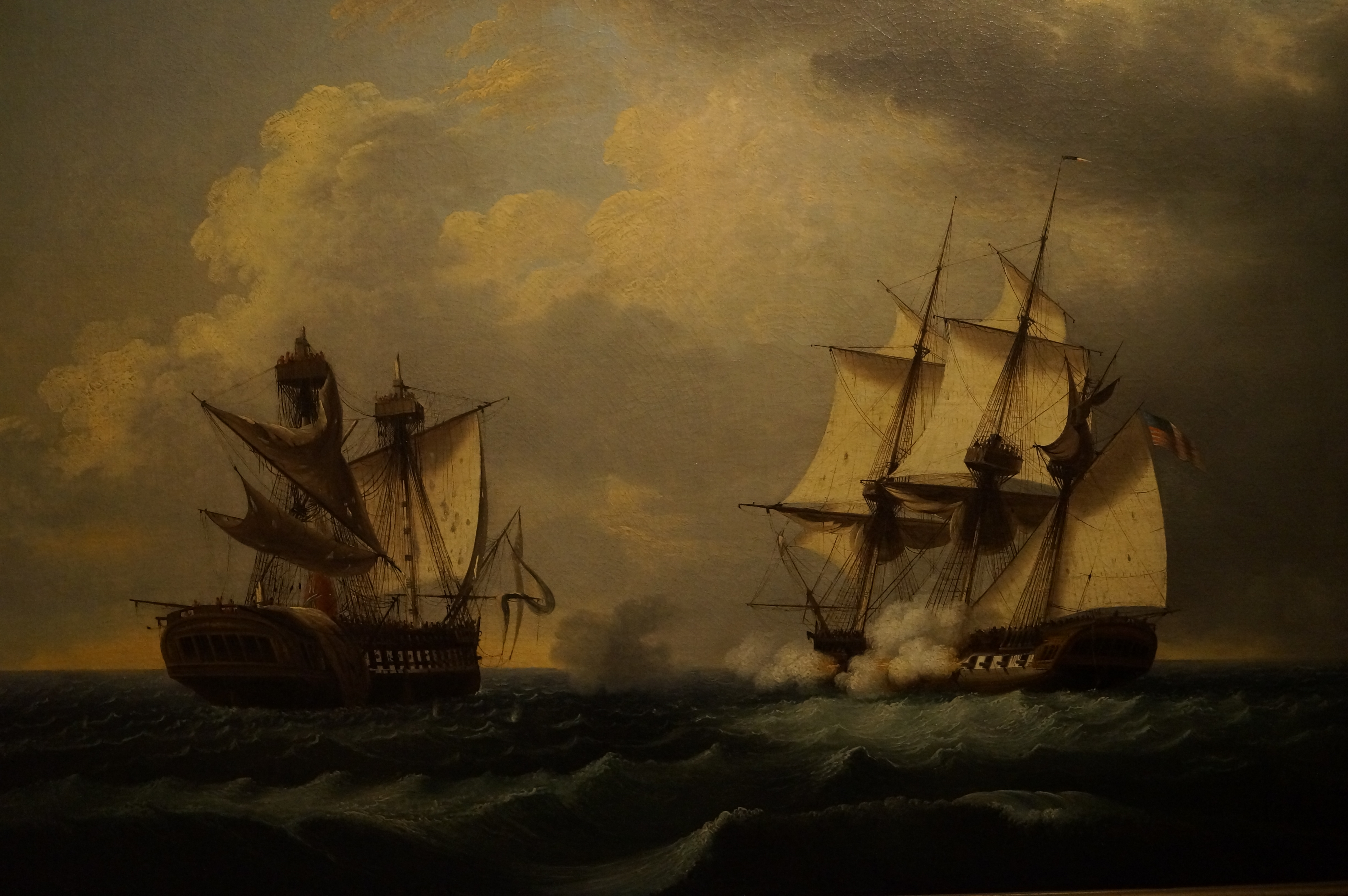
In that first picture it looks like the one in the background has a quoin. Not sure if there was a time period or any specific reason to use one or the other.
btw MS 32 lb Carronade kit has the screw mech.
-
 MEDDO got a reaction from thibaultron in Granado 1742 by DocBlake - FINISHED - 1:32 Scale - Bomb Vessel Cross-Section
Coming along nicely Doc
-
.thumb.jpeg.fc5d633a7b34428fcf19419a73d56d55.jpeg) MEDDO got a reaction from EricWilliamMarshall in 21ft English Pinnace by Mike Y - FINISHED - Model Shipways - 1:24
MEDDO got a reaction from EricWilliamMarshall in 21ft English Pinnace by Mike Y - FINISHED - Model Shipways - 1:24
I have always used old t-shirts for the wipe on poly. (I basically have a lifetime supply from my time in the military). They seem to work great and don't ever produce the "fuzz".
-
 MEDDO got a reaction from wyz in Boat/barge for the Winnie
Definitely go for it. If it cannot be built by us mere mortals then at least you have learned something along the way
-
MEDDO reacted to Beef Wellington in HMS Snake by Beef Wellington - FINISHED - Caldercraft - Scale 1: 64 - First wooden ship build
Ensign...conclusion:
A tiny bit of steam was used to soften the ensign while various "rounded implements" with different radii (dowel, metal file shafts etc.) were used to try and introduce various folds. I'd love to be able to describe a reproduceable scientific process, but thats not what happened. It was really just a continual serious of tweaks, leaving to dry and most importantly trying not to introduce creases. Steam worked fine to initially soften and allow the structural folds to be introduced, but isn't really a good ongoing solution as it tends to undo any previous work. Real care is also needed to not 'over wet' the painted flag, not sure I was completely successful here. Final tweaking was done by wetting very gently any tools used and trying to hold in position while it dried and the fold takes.
...and with that milestone, I'm declaring this build FINISHED!
This was my first wooden ship build, and first model I've built for over 30 years. Its taken probably 8 years to get this far off an on (probably 7 years more than it should), but I have to say I'm glad I was able to finish her. I've come to realize that I enjoy the journey more than the destination, and I certainly experienced moments when I could easily have put her aside permanently, mainly due to me recognizing unfixable mistakes or compromises that that could so easily been enhanced had I known more at the time. Given the length of time taken to complete, this progression in knowledge and execution is very apparent to me, but I hope is less apparent to others. All in all, this was a most enjoyable project that exposed me to the necessary knowledge and techniques that I hope build on and leverage in the future. I still need to make up a protective case, and will probably continue to see needed fixes and touchups before she (hopefully) is put in a place of rest. I would like to thank this entire community for the ongoing help, support and encouragement - without which I would not have reached this point.
Few pictures to celebrate, apologies that these aren't exactly studio quality.
-
MEDDO reacted to vaddoc in Sharpening chisels - my (relatively) simple way
Dear all
I am no wood worker but I have come to appreciate what a wonderful tool a very sharp chisel can be. However, no matter how expensive or cheap a chisel is, it will need to be honed continuously and will only work as intended if it is really scary sharp.
There are many ways to hone a chisel and various types of stones and jig are available, some very expensive. Please allow me to share how I sharpen my chisels. Now, there are a few tools that are needed but are not too expensive and will last for a very long time.
I recently bought a new chisel, an 8 mm Narex so I thought it was a good opportunity to show how it can be turned into a useful tool. I hope that this will be of help to others.
I like Narex chisels very much but out f the box they are of no use at all. The tip is covered but some kind of lacquer and is not sharp. The bevel and the back of the chisel are very rough.
Now, for the chisel to be sharp, both surfaces need to be as polished as possible. So lets start honing this chisel
We will first concentrate on the back of the chisel. This surface will only be worked once, on purchase and will not be touched again. Until the back is flat and polished to mirror finish, we cannot proceed.
I will use only a cheap combination diamond stone 400/1000 grit, a slightly more expensive 1200 grit diamond stone, an old leather mouse pad turned upside down, a sheet of flat MDF and green polishing compound. I also will use a honing jig I make myself. This jig is absolutely needed unless you have a very steady hand and lots of experience, it can be made with whatever scrap material but some accuracy is needed in its construction-basically a drill press or a very steady hand.
Another thing needed is some kind of jig to make sure the bevel is grounded at roughly the same angle each time the guide is used. I just use scrap wood for this
Now, we start by positioning the chisel on the jig, finding the angle and then marking this position on the scrap wood. The little pieces of wood are glued and then screwed on.
Now we start honing. I start with the 400 grit trying to remove the machine marks. This is the starting point
And this is how it looks after a few passes
Then we move on to the 1000 grit. This is how it look afterwards
Then on to 1200 grit, this is the result
However there is a problem. The back is not flat as the next photo shows
This is a problem. The back needs to be flat or better concave, so that less material needs to be removed making the job easier. So back to 400 grit to remove enough material to make the back completely flat, so the tip touches the stones. The diamond stones are very aggressive, they do not need any pressure, just to move the chisel back and forth.
This is how it looks now at 400 grit...
at 1000 grit...
and at 1200 grit.
The chisel is already very sharp but we have a long way to go. Next comes the strop. This is how it looks after a few minutes of stropping.
I have found that the fastest way at this point is using MDF. I charged some MDF with the green stuff and starting polishing like crazy moving the chisels in all directions. After just two minutes the results are impressive.
30 sec later
and after 30 more seconds of polishing, we are there. These are my fingers holding the phone shown on the surface, it is like mirror.
Good, now we move on to the bevel. This is our starting point.
Using the jig we made earlier, the chisel is positioned on the guide. However although close, the positioning is not accurate so we actually need to create our own bevel. So we start with the 400 grit. This is how the new bevel is progressively formed.
Then on to 1000 grit...
and to 1200 grit.
Then we move on to the strop. The bevel takes much less time to polish than the back and actually the leather works better than the MDF. This is the result.
We now need to do a few passes on the back to remove the excess material hanging of the edge.
The chisel is now very sharp, sharp enough for what I needed for. It can of course be further polished, the green stuff I think is something like 25,000 grit but it is enough for now. During use, every few cuts, I make a few passes over the strop. With some use, it will get further polished.
I hope this has been helpful for some, a video follows showing the surfaces of the chisel
Regards
Vaddoc
-
MEDDO reacted to marsalv in Le Gros Ventre by marsalv - FINISHED - 1:48 - POF
To Hubac´s Historian - Thanks for compliment.
I still have some rest at the stern - decorations.
-
MEDDO reacted to mtaylor in Fitting and Rigging a 74-gun Model Ship
Fitting and Rigging a 74-gun Model Ship
Francis Jonet
ANCRE (www.ancre.fr) – December,2020
118 pages-color photos-diagrams
This is an updated reprint of the original book’s first printing and is available in French, English, Spanish, and Italian.
Overview:
While not part of the seminal books by Boudroit of the 74 Gun Ship series, it is an add-on that complements the series. This book provides references and how-to instructions. Numerous images (both color photos, drawings, and tables) illustrate the items and the techniques using a minimum number of tools. Everything included relates to construction of the 74-gun ship from late 18th to the early 19th centuries. Do note that the first chapter is dedicated to finishing the upper works and fittings as well as what’s required to add the rigging.
Contents by Chapter and sub-headings:
Chapter I – Fittings and more, Tools, Laminates, The sandpaper file, Working on the stern and stem, Making gratings, Upper deck and Poop deck breastwork, The breast rail stanchions and belaying pins, Ladders, Shroud chains, Anchors, The guns, The figurehead, The stern lantern
Chapter II - The Masts – Making the spars, Lower mast and lower yard hoops, The yardarms, Building the tops, Topgallant trestletrees and crosstrees.
Chapter III – Blocks – Preparing slats, Making the shells, Finishing the blocks
Chapter IV - Rope Work – The workspace, Theory, In practice, Serving, Particular cases for small cables
Chapter V – Finishing the Ropework – Eyes and mouse (stays), Shroud masthead rigging, Rope bights, The shrouds, Wall knots, Ratlings, Hammock nettings, To clap on blocks to the yards, Small block straps, The thimbles or rings, Hooked return blocks, The anchor buoys
Chapter VI – Making the Sails – The cloths, Tabling, Linings and patches, Eyelets, Bolt ropes, Foot ropes, Head ropes, Bolt ropes cringles, Reef point, Gaskets, Grommets, The bent sails
Chapter Vii – Installation of the Sails – Leading and belaying the ropes, Jibs, Staysails, Lower sails, Topsails and mizzen topsail, Topgallant sails and mizzen top gallant, Driver, Jib sheets and Installation of anchors, Finishing the Installation of square sails, Staysails sheets, Inspection of the work done
Chapter VIII – The Ship’s Boat – Construction method, The forms, Framing, Keel, Stem, and Sternpost, Sterns, Planking, Form removal, Stern sheets, Floor timber and inner planking, Thwarts, Stem and stern inner areas, Rudders, Finishing details
Chapter IX – Technical Data – Making the ropes, Shrouds, back-stays, stays, Preventer stays, bowsprit mast, Catharpins, range cleats, belaying cleats, Blocks, sheet blocks, staysail stays, bolt ropes, foot ropes, etc. Fall tackles, yard tackles, Sail tackles, anchor ropes and cables, Yard rigging, Lower sail clusters, blocks for the stays
Chapter X – Block Distribution – Rigging parts for the masts and for the operation of the yards, Rigging parts for the operation of the sails, Rigging parts for the operation of guns.
Chapter X – Return Tacks – Forecastle, Quarterdeck, Poop deck.
Technical Data – Tables for all of the rigging, blocks, and tackle sizes,
Review:
This is basically a journey, in which shows not just the author’s successes but also his failures, both of which are useful. Every chapter details the jigs he used along with the methods, along with photos of this process which, was eye-opening to me and would be useful (with modification) of any ship of the period.
While there are minimal plans (you will need the monograph for the model you’re building), the appendix has much to offer in the way of tables which not only surprised me but somewhat overwhelmed me by the amount of data there.
The book is well-written with the photos being annotated to explain what is being done. Everything is broken down into bite-sized chunks and processes used explained.
Though I have no intention of building a 74, as my preference is frigates, the same techniques and tools will be very useful and save me a lot of “re-do’s” and figuring out how to do it.
Would I recommend this book? Yes, very much so as it will help any builder come terms with the complicated rigging. I’ve decided that this is one the books to keep at all times near my workbench instead of in the library. I really can’t recommend this enough.
-
MEDDO reacted to glbarlow in HM Cutter Cheerful 1806 by glbarlow - FINISHED - 1:48
I’m continuing to do mini-projects in no particular order - following the ‘why don’t I do that next’ plan. So:
Mounting the rudder
When I first looked at the Pintles and Gudgeons mini-kit I wondered what do you do with those. Turns out it’s another brilliant design and a simple way for attaching the rudder. Simple in concept anyway.
The first step was to paint the gudgeons Ironwood Black then dust them and the straps with weathering powder, because you know you can never do enough weather powdering. Attaching to the rudder itself was straight forward, I left the pintles long initially then trimmed it back after some test fitting.
Then came the more challenging part, attaching the gudgeons to the hull in the right place to fit the rudder and in line. After some careful measuring and marking I used a piece of brass wire to make sure they were aligned. There isn’t any forgiveness here, everything has to be in the right place.
I encountered a problem, I couldn’t get the glue to adhere to the hull, after several frustrating attempts I determined that glue sticking to wood with too many coats of WOP doesn’t work - I simply had let it get it too thick on the stern post. I roughed up the wood with some 220 grit, and after that no problem. I of course knew this, but sometimes in the thick of it you just want the wood to shut up and do what you tell it to do - the wood laughs. I also shouldn’t do these things at night, or maybe not at night after drinking scotch, or maybe just not after drinking scotch.
Anyway. The straps and bolts are added. I liked how drilling holes as marked on the strap, inserting wire a little long to glue it in and then cutting it near flush made for nice bolts after touching with Ironwood Black (a little touch up there to do on the hull too, oops).
And there you have it, my ship can now be steered should it find itself adrift in the ocean somewhere. I still think I’m going to remake the tiller, we’ll see, it’s just hanging there loose for the photo. So with that done the rudder is removed and put on the shelf to be permanently installed later, bye rudder.
The Catheads
Then, since it can be steered I figured I better be able to anchor it, so do the catheads next. That meant it was time to play with the mill again and pretend I know what I’m doing. Following the monograph I constructed the catheads in two parts. First the upright, which to fit tight against the bulwark had to be notched for the spirketting and again for the waterway. I cut both notches with the mill. While it takes the unskilled like me a bit of work and trial effort to get the measurements right, the mill cut nice and clean once I had it correct (actually it cut nice and clean when I had it wrong too). I bought a car engine feeler gauge, took it apart and used the thinest one to set a good zero for between the bit and the wood for the X,Y,Z axis. This proved pretty handy in getting a consistent starting point for the cuts.
It was fortunate I read the monograph first (not that fortunate as I always do). Before starting on the catheads, the forward pin rail has to be made and installed. That has to be sized carefully so that the cathead doesn’t impede the flow of the anchor rope through the hawse hole or restrict the gun tackle for the forward chase port, there isn’t that much room between the two. I had to do a little fine tuning on the pin rail not related to the cathead as shown here.
Next up is getting the correct angle on the upper piece of the cathead, hint, it’s not 90 degrees. There needs to be some upward angle to it, while also accounting for the bit of lean of the upright on the bulwarks. After some experimenting I determined 85 degrees was best (or 95 degrees depending on how you look at it). Since the Byrnes gauges don’t do notch anything less than 15 I set the angle on the sander for a smooth edge using a digital protractor. Then to get a good feel for it I set the top piece on for a look. I decided this made a great ship's crane and installed it just like shown here. Well, it did cross my mind for a second. When I know I’m going to need multiple equal sized pieces, plus several more for testing I cut a properly sized long length and cut everything from it, hence the long piece shown.
Then its back to the mill to cut the sheaves into the top piece. This is so incredibly easier and better than doing it by hand with a blade as I’ve always had to do in the past. Just cut the slots a 1.5 mm deep and drill all the way through on both ends. I added flush-cut 24 gauge wire to either side later but it doesn’t go all the way through and is just for simulation.
This little Veritas triangle, a new tool, has been coming in handy a lot for deck work, here to make sure the cathead is perpendicular to the deck.
Some filing at the leading edge, paint, a couple of cleats, and I have catheads. No anchors yet so the ship is still drifting, but at least they have someplace to attach one, or maybe attach Fred, their fellow crewman who drank all the grog, and just let him hang there a while. BTW, they are straight, the photo is a warped perspective due to the angle.
The Seats of Ease
I struggled with the concept of this a bit. These seats are such a prominent feature of the deck. I have this vision of two crew members availing themselves of the seats, just a few feet from the helmsman. There is no cover on them (I almost added one) so I wonder, given the prevailing wind on a sailing ship is generally from either rear quarter, if the helmsman - often the captain on a ship this size - was constantly bombarded by the smell. So I almost turned them into lockers and let the crew poop over the rail. In the end I decided to stay true to Chuck’s design and accepted they’d be a topic for conversation once the ship was finished. So I began to build my two onboard outhouses with apologies to the helmsman…courtesy flush dude (which would be a bucket of water I suppose).
It seems simple, just glue together three pieces of wood, the top, one side, and the front. The thing is, again, there are a lot of angles and curves involved - plus you are making two and the two have to be both identical, level and even in height with the spirketting since that forms the outboard side, and the width of the inboard stern frames. Here’s hoping I installed all of those equal on both sides so long ago. I started by cutting card templates (as Chuck suggests) - its kinda essential here to get the right fit. I’m sure there is a geometric name for the shape of the top, let’s just say it doesn’t remotely resemble a rectangle. I also cut a long strip 9mm wide from 1\32 sheet so that the front and sides for both seats came from the same piece of wood.
This photo is from later in the instruction. I first did the sides since everything else is based on them. The challenge is cutting the curve of the counter on the bottom, having both end up the same height and level, be the same length coming forward, and the leading edge perpendicular to the deck…no problem…who doesn’t love geometry.
And what do you know on the first try both sides are level…or maybe not on the first try…
After cutting the fronts - with the outboard side beveled to fit snug to the bulwarks, it was on to the top. There is no substitute for card templates here. I marked the measurements, tested it and remarked until I had the varied lengths on the four sides required for it to fit, the angle of the hypotenuse or something like that. I used the cross cutting table on my Byrnes saw to get precise cuts on two of the sides, there is likely some way to do it with the saw, but I opted to cut the remaining two sides with my heavy steel rule and #11 blade. It’s possible I didn’t get all this right on the first try, card stock or not.
With the pieces cut and only the sides glued in I test fitted everything, and found it’s all level and equal sized, how’d that happen.
The last step before mounting and painting is the ease part of the seat, cutting the hole, which after all the work to get two fitted tops I didn’t want to screw up. So I went slow with a small pilot hole, then a bigger one, then a round needle file, then a larger file marked with a sharpie to finish at a 4mm hole, and finally an ultra fine sanding stick to smooth it out.
I added two large cleats and 4 smaller ones then painted it by brush with thin coats of my favorite RED (again some iPhone camera distortion on the angles). The cleats come from Syren, available in multiple sizes. I had to remove the laser char (it would show through the red paint) and shape them a bit. I used the stem of a standard eyelet to pin them to the bulwark so they can take rope tension later. I also added the horse, created from 24 gauge wire. I used the eyelet portion, cutting off the stem flush to the circle, to accent the horse either side, painted it Ironwood Black and weathered it to finish off the stern - except the knees and boom crutches which are up next…maybe…
Pin rails and cleats
I finished up this phase by adding the bulwark pin rails along with the rest of the cleats noted on the plans. Turned out to be a pretty tight fit for the cleat nearest the ladder. I’m glad I checked that, I had to give it a little extra turn to allow the ladder and gun tackle to fit with room for the future lines shown on the rigging plan. It’s generally a good idea to take a look around at what might happen or be added later to make sure nothing gets in the way of something else. That was evident here and especially evident with the catheads.
As I noted I’ve been turning pages in the monograph and doing what I felt like doing next - at this phase, at least so far nothing has to be sequential, though that will change soon. Thanks everyone for the likes and for stopping by. I better go check to make sure the crew didn’t actually drown Fred.
-
MEDDO reacted to Chuck in HM Cutter Cheerful 1806 by JpR62 - 1:48 scale
You could also use the actual interior for Cheerful.....rather than use one from the much older Alert.
-
MEDDO reacted to EricWilliamMarshall in English Pinnace by EricWilliamMarshall - FINISHED - Model Shipways - Scale 1:24
I made some more of the frames that decorate interior. Gluing was a little fiddlely but yielded to practice. I traced the shape from the frames on to the boat. I then added some paint to what will be inside of the frames when attached. The one frame in the boat is just a dry fit.
-
MEDDO reacted to EricWilliamMarshall in English Pinnace by EricWilliamMarshall - FINISHED - Model Shipways - Scale 1:24
A bit more work on the moldings.
-
MEDDO reacted to jdbondy in Mary Day by jdbondy - 1:64 scale (3/16" to 1 foot) - Schooner
In a previous post I went over creation of a transom filler block, created by obtaining measurements off my half model of the Mary Day hanging on the wall of the shop. In order to put that filler block on the work surface, I had to extend the baseboard. In its current form, the filler block rests against the aft surface of frame #50, shown here inside of the sternpost.
This wood strip was attached and the surface was planed flat with a block plane. Frame 51 is shown in place here, just aft of the stern post.
Next step is to cut the transom filler block so that it can rest against frame 51. I used the table saw to cut slots of appropriate depth. These were joined to form a flat surface that would rest against frame 51.
In the centerline, a large timber extends aft from the sternpost and supports the transom planking in the centerline. To accommodate that timber (I will call it a horn timber, which would be correct in other designs but I’m not sure if it’s the correct term for a schooner such as this), a slot had to be created in the centerline of the transom filler block. Plus the plans show additional smaller timbers on each side of the horn timber, so the slot was made wide enough to accommodate all 3.
A slot also had to be created in frame 51 to accommodate the horn timber.
Transom framing has been added on each side of the horn timber, which enabled me to go ahead and attach that horn timber to the sternpost.
The plans indicate that transom planking only begins a certain level above the sternpost, so these smaller transom frames are notched at that point where the transom planking begins.
Next I carefully marked on the filler block the location of the other transom frames, and used the table saw to cut slots in the filler block to accommodate those frames. There are a total of 5 frames on each side of the horn timber.
At a certain point, I remembered that the transom is not flat across its face, but it has a certain degree of camber. The builder’s plan and line drawing were able to give me a sense of the degree of curvature, and at this point the filler block was sanded to a curved surface on each side. So each of the most peripheral slots had to be deepened to make sure that once they were glued in place, they would form a curved surface for the planking. I only remembered to mention this as I was putting this build log post together!
The filler block in place with the most central transom frames and no keel/horn timber assembly.
The starboard side transom frames have been glued using straight butt joints against the aft surface of the last frame.
All the transom frames were glued up, but I came to realize very quickly that the butt joints were not stable enough for practical use. So I pulled them off…
…and went to the microscope to carve out mortises that would receive each transom frame.
Since the assembly consists of frames 50 and 51 joined by some blocks adjacent to the centerline, the outside edges of 50 and 51 are unstable. I stabilized them with the pieces of wood shown above, slotted in between the two frames.
Transom frames are being glued in place again, and glue squeeze-out was carefully removed using the microscope.
That results in an assembly that looks like this. The frames are still solid sheets of wood at this point. To carve all the wood out from inside the frames would leave a very unstable and fragile structure. So the plan is to carve out the wood to the level of the deck beams, leaving the bulwark stanchions in place.
To further stabilize this modular transom assembly, I decided to go ahead and apply some transom planking. The first plank is in place…see if you can figure out the problem I just created. The horizontally oriented slots in the filler block helped to make sure the plank was perpendicular to the transom frames.
It is pretty cool to separate this modular structure from the transom filler block and find yourself with a stable assembly. I started with a solid block of wood, and through process of wood elimination I will hopefully end up with a respectable transom assembly that actually resembles the real hull framing structure.
Two more transom planks have been added before I figured out the problem I had created. I think I was out of the room when I thought…wait a minute, I can no longer put the keel/horn timber assembly into the transom framework! I walked back in, and sure enough, when I tried putting the keel back in place, I ended up with this.
The solution was to separate the horn timber from the sternpost, with the plan to make it part of the transom assembly.
Now to eliminate more wood. I had to figure out how to carefully carve out wood I didn’t want from frames 50 and 51. But to carve carefully, I would have to figure out how to hold this complex structure steady. So in the above picture, frame 50 is clamped between two thicknesses of wood that are separated by a sheet of wood that is the same thickness as the frame it is holding. Plus I have some grippy rubber material in there too.
Holding frame 51 still is more complicated, due to the transom frames. So I slotted out some wood from a block that would fit between the frame and the planking that had been applied.
Looks something like this.
This is positioned high in the clamp for the sake of the picture. In order to actually do any carving, though, the clamped frame would have to be low in the clamp to minimize movement.
A Japanese crosscut saw was used to slowly and carefully create the slots in each frame. They could only go to a certain depth before they would be in danger of cutting the transom planking. Then I used a ½” chisel under careful control to slowly cut away material from the frame while leaving stanchions behind.
Despite all that care and control, you can see how the chisel would still hit frame 51 and leave behind lots of little cuts. Fortunately the affected wood of frame 51 will be removed later on.
Finished removing wood from frames 50 and 51, for now. The deck camber was marked by using patterns for deck beams I had created earlier. Wood was removed up to those pencil marks, but not beyond. I figure there will need to be deck fairing later on.
This has been fun creating this modular transom structure! I plan to harvest the outboard edges of the filler block and install them to the transom assembly in order to define the outer surface of the transom and to give the bulwark planking something to key into.
Big decisions lie ahead when it comes to hull planking. I honestly don’t know what I am going to do after planking the transom and trimming its edges to accommodate the hull planking. But things just seem to be making themselves apparent to me as the work progresses, which is really cool.
-
MEDDO reacted to Alex M in HMS Sphynx 1775 by Alex M - Scale 1/48 - English 20-Gun Frigate
Hi,
the planksheer and timber heads are now done, working further on open rail. the images show it
Regards
Alex
-
MEDDO reacted to carlosgf in Seawatch Books
Hi all,
Additional plans (frames, etc...) are in the CD.
Volume 2 includes addendum to Volume 1.
-
MEDDO reacted to GuntherMT in Seawatch Books
Some sheets you need to print yourself. Sheet 2 is the Shipway Plan drawing and will be found in the Chapter_04 folder on the CD for the 1/72 scale version.
Sheet 8 is the 1/96 scale shipway plans and is also included on the CD and is referenced by EdT in this post in the thread specifically about these books - https://modelshipworld.com/topic/11317-modeling-the-extreme-clipper-young-america-1853/page/2/?tab=comments#comment-687297
-
 MEDDO got a reaction from mtaylor in Mary Day by jdbondy - 1:64 scale (3/16" to 1 foot) - Schooner
Glad you and the family are doing better. Wonderful progress there. You have accomplished quite a bit since the last update
-
MEDDO reacted to JpR62 in HM Cutter Cheerful 1806 by JpR62 - 1:48 scale
Thank you to the people who follow this build.
Installation of bulkheads. And here all the difference in quality and precision of the kits produced by Syren appears.
When I remember it took me over a week of work to prepare and test the bulkheads setup on my Armed Virginia Sloop.
With the Cheerful, in ten minutes, the bulkheads blank test was done and I was able to start gluing them.
I had fun with my children's legos again. 😄 They won't hold it against me. They are now adults and have other interests.
Finally, I prepared a working basis to deposit my model.
I also planned a second base in anticipation of the fairing. I will probably raise it to make this task easier.
But before this phase, I'm going to reinforce the bulkheads and make a first modification to the model. I plan to add the detail of the captain's cabin which will be visible through the skylight.
-
MEDDO reacted to jdbondy in Mary Day by jdbondy - 1:64 scale (3/16" to 1 foot) - Schooner
It has been since August that I posted on any model work. I have indeed been distracted by projects related to the new sailboat, but other things were going on, like COVID 19 working its way through our household in December! But work on the model has been occurring, relating to planking prep and construction of the transom. The transom work is particularly interesting and challenging. I hope to do a couple of posts in relatively rapid succession to bring things up to speed.
This is an example of how lucky I am when it comes to the documentation of my subject. Cap’n Barry gave me a shell diagram to the Mary Day that lays out the planking on each side of the hull. He explained that each plank’s age is tracked because at any time the Coast Guard can ask for a sample of a particular plank. I suppose that means they take a core sample, then fill the hole with the equivalent of a treenail. Their shell diagram keeps track of when particular planks have been replaced and where samples have been taken in the past.
For our purposes, the width of each plank is documented with respect to where the plank crosses a particular frame. I bring this up at this stage of the build because I need to be able to visualize how the planking bands lie, particularly as the bands approach the transom, so I can properly fair the frames (and stern filler blocks, if I end up using them).
Also included, but not shown here, is a planking diagram of the transom.
The first step of the process was to take each of the 3 sheets depicting the shell diagram and merge them into one image.
At each major station location, the width of all the planks was totaled and used for the denominator, then the widths of the planks within a band were totaled.
The length of the tick strips was determined by the length on the model from the rabbet to the level of the bottom of the covering board, which is effectively where the hull planking meets the level of the deck planking. The tick strips were then divided according to the relative widths of the planking bands.
Marks from the tick strip are transferred to each frame so that despite fairing the frames, the placement of the bands will still be evident.
The lovely wife serving as my hand model for this picture.
I have marked the edges of the planking bands with red or green marks. These will of course get obliterated as I do more fairing, but they can be restored after that is finished.
I started with four planking bands, marked in green, but realized that as you approach the stern, I needed to add a band to cover all the additional territory that opens up. That is marked in red.
So the tape gives me a sense of how the planks approach the transom. Portions of the transom filler block have been carved away on each side.
I was told there would be no math. But I needed to know more about where the planks land on the transom, and how much I would have to rebate the filler block for the hull planking and the transom planking to meet at the right point.
Using that information, I drew a new curve on the transom that was set back the appropriate distance (3/16” maximum) and carved to that curve.
This was carried out on the other side.
In order to try to keep the shape symmetric, I tried using some creative “feeler gauges” to make sure I was rebating to the same depth on each side.
But I ended up just doing it by eye.
Back to the rabbet. Here I am checking the depth and angle of the rabbet at a certain frame location with a small piece of wood that is the same thickness as the hull planking, 3/64”.
The rabbet was extended in the same way as it would be done at full scale, creating reference points of appropriate angle and depth, which are then connected up.
The rabbet has been extended to the start of the deadwood.
The rabbet carved into the port side deadwood.
And the same for the starboard side. The blue tape prevents scuffing of the keel timber.
Before forgetting to do so, I worked on shaping the contour of the stem, which narrows from the full width of 5/32” to a minimum of 1/16”.
The narrowing of the keel hasn’t been finished on this picture, but you get the idea. One nice thing I was able to do with the microscope was to achieve a really smooth finish after sanding to 320 and 400 grit by scraping with a razor. I will eventually do that with the rest of the keel, but I have to make sure that fairing is finished first so I don’t accidentally mar the finish.
At this point, I feel confident enough about the frame shapes that I wanted to try to preserve them for the future.
So I traced out the shape of each frame (larger side of each frame, of course) onto card stock, and scanned them into PDF files.
Maybe this will come in handy in the future.
So the next post, which will hopefully follow soon, will focus on transom construction. It’s nice to be back at it!
-
MEDDO reacted to EricWilliamMarshall in English Pinnace by EricWilliamMarshall - FINISHED - Model Shipways - Scale 1:24
As per the instructions, I cut the traced lines with an x-acto blade. I cut the pieces wide and glued them to the pinnace. I then used a chisel to cut the inside curve and then a bit of sanding. I then could mark the outside line and trim with a block plane and sand paper. I then attempted to use a scraper on the edge of the rail with mixed success.
-
MEDDO reacted to EricWilliamMarshall in English Pinnace by EricWilliamMarshall - FINISHED - Model Shipways - Scale 1:24
And a bit more paint!
-
MEDDO reacted to Bill Brown in HMS Cheerful by Bill Brown - FINISHED - Syren Ship Model Company - 1:48
Thanks Mike! Miss seeing you guys. Looking forward to being able to get back together this year.
Meddo,
thanks for the kind words. You will enjoy this project. It is well engineered.
I look forward to following your build log.
-
MEDDO reacted to bartley in HM Cutter Cheerful 1806 by bartley - FINISHED - 1/48 scale
Post 49: Bowsprit Installation
The bowsprit itself was constructed and test fitted earlier when there was less deck furniture to obstruct it. It is now time to install it permanently. The bowsprit is fed through the bulwark hole hole in the bow and inboard end is located by the lower strip of the bowsprit step. As Chuck points out it is not necessary for the strip to bass all the way through the bowsprit. The strip can be cut in half and inserted about half way through the bowsprit from each side . It appears to go all the way through. The windlass fits behind the bowsprit step with the pawls engaging in the ratchet wheels.
In fact, when I was manipulating the bowsprit later on the bowsprit step detached. It was clearly not glued down securely. I had to remove the windlass to attend to this and the bowsprit step is now re-glued pinned to the deck with twisted pair pins like these:
Whilst on the subject of the fore-deck it is clear that once the bowsprit and step are in place there is insufficient room for recoil of the port chase gun.
This fact has been pointed out by several other builders. The second gun-port is vacant but positioning this gun there makes it look unsymmetrical. The plans show the gun in this position and and the specification calls for "two 6 pound chase guns" so I have chosen to leave it positioned as shown even though it could probably never be fired in this position.
John
-
 MEDDO got a reaction from FrankWouts in Seawatch Books
Great company and great service. I just received this today. I had ordered the book (and received it) back when it was first available.