


JSGerson
-
Posts
2,480 -
Joined
-
Last visited
Content Type
Profiles
Forums
Gallery
Events
Posts posted by JSGerson
-
-
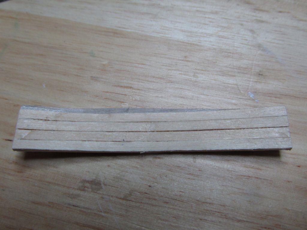
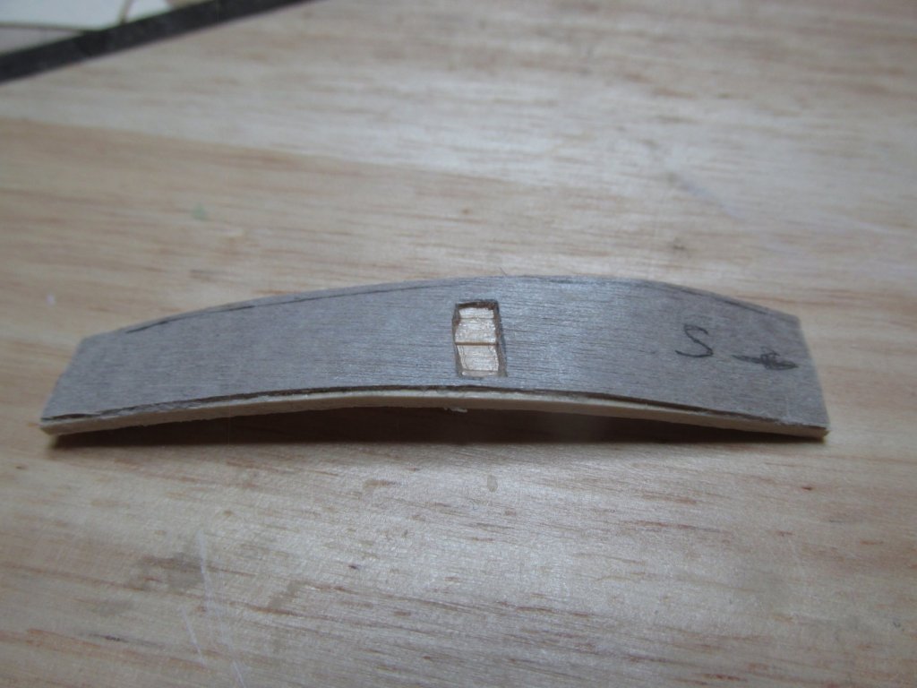
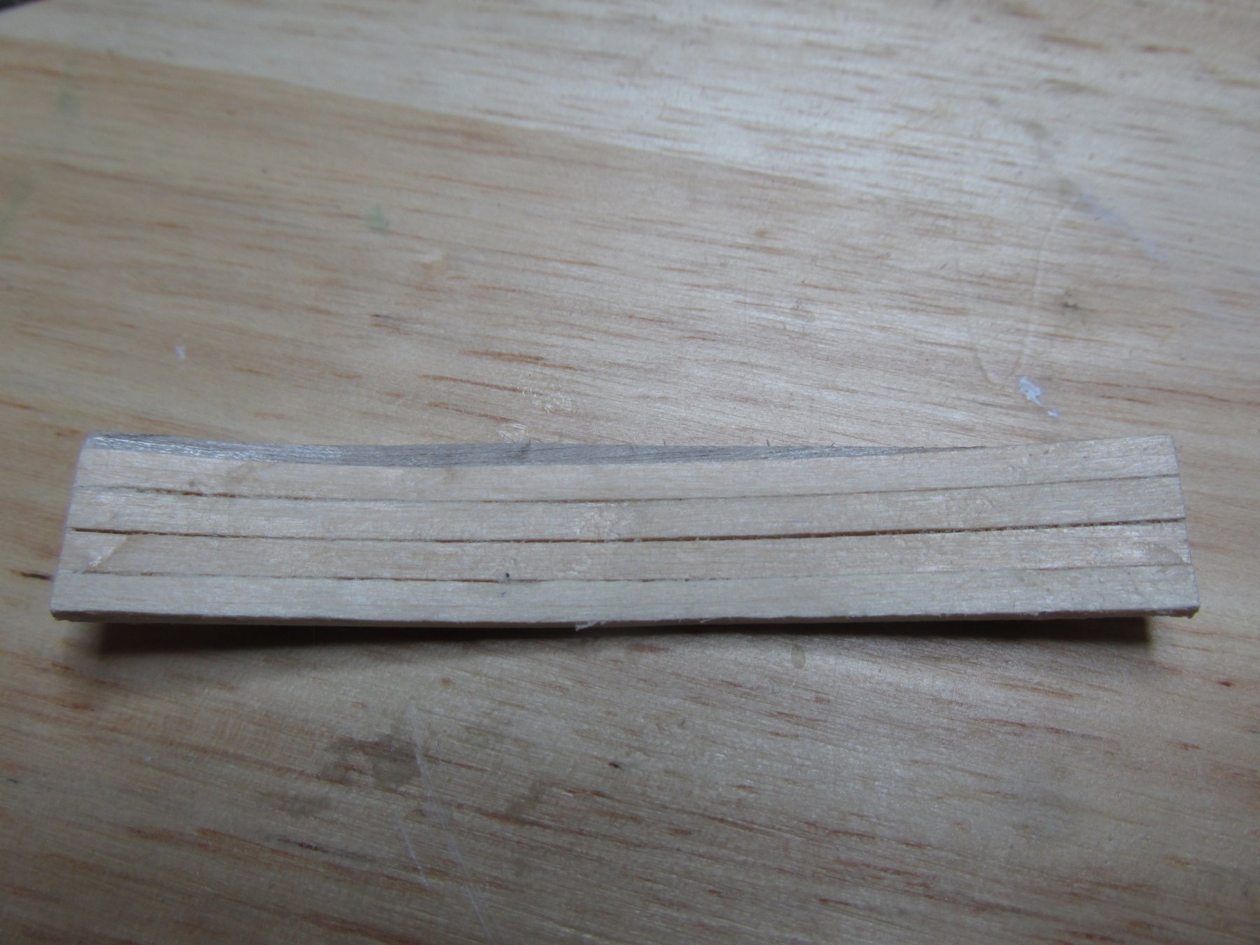
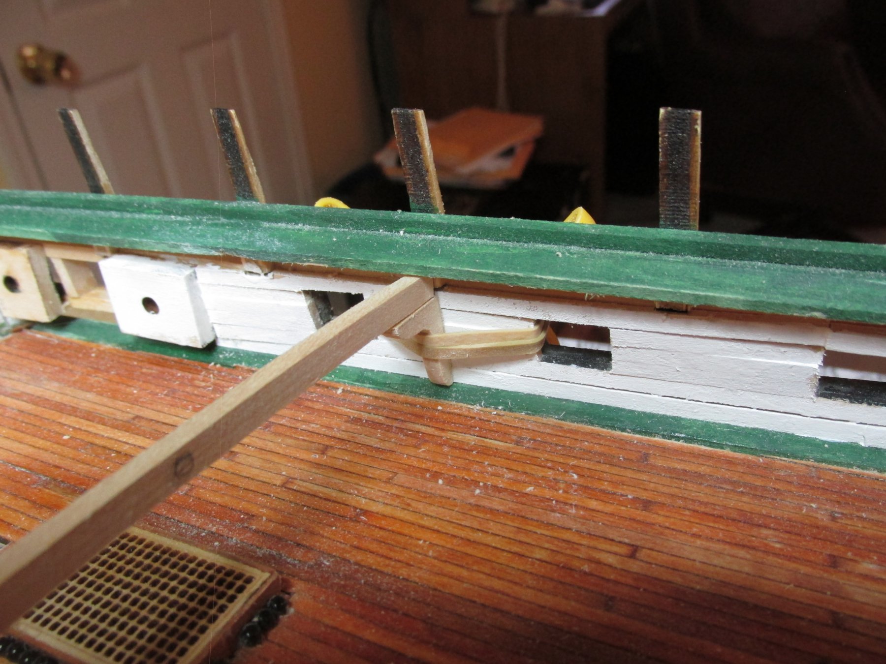
Like the plywood, strips of 3/32” x 3/64” basswood supplied by the kit were cut to the approximate length and soaked. I was able to press the wood to the complex bends for these pieces with my fingers against the now dry and formed backing. The wood strips were glued right over the cathead openings cut into the plywood and left to dry. The markings on the backside of the bulwark backing shown below, indicates that it fits on the Starboard side and the arrow points to the bow.
-
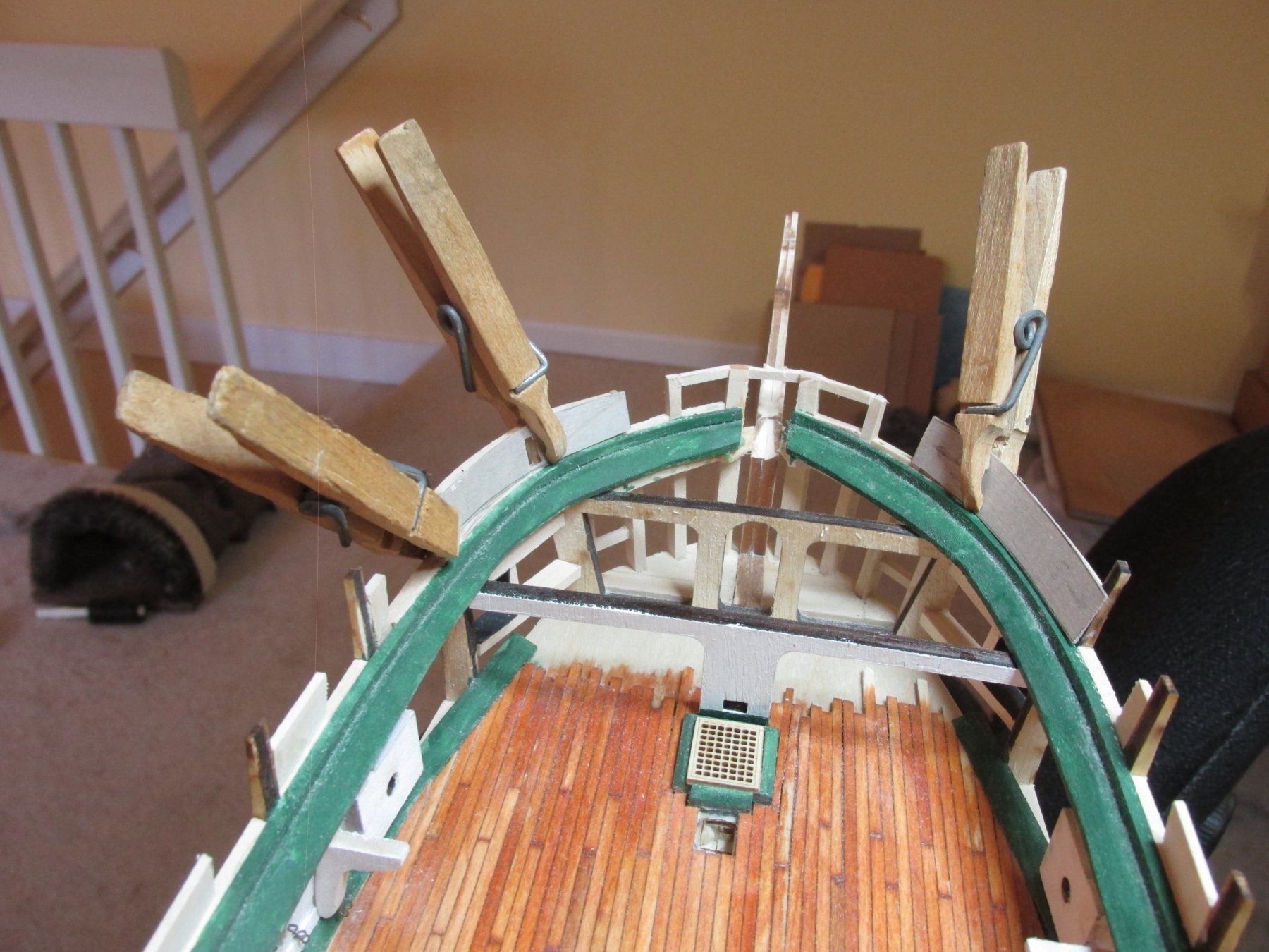
Since I started the bulwarks at the bow with my prototypes, I just continued aft. The bulwarks next to the bow I consider to be the toughest to make…so far. Every piece of these bulwark constructs must be formed into a curve shape conforming to the frame. After numerous false starts I started to make some headway.
As before, I started by making card stock templates for the 1/64th birch plywood backing. After I marked and cut out the openings for the catheads in the plywood, I soaked them in water for a few minutes to make them flexible. The backings were then placed in positioned and held in place with clothespin clamps. I left them there overnight due to its complex bend. The bow curves both horizontally and vertically as the bulwark angles outward around the curve of the bow.

-
Good to have you back
- JeffT, CaptainSteve and mtaylor
-
 3
3
-
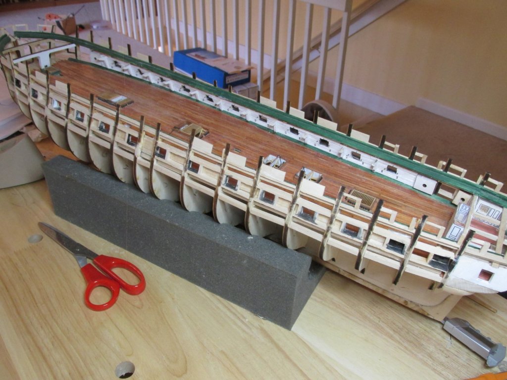
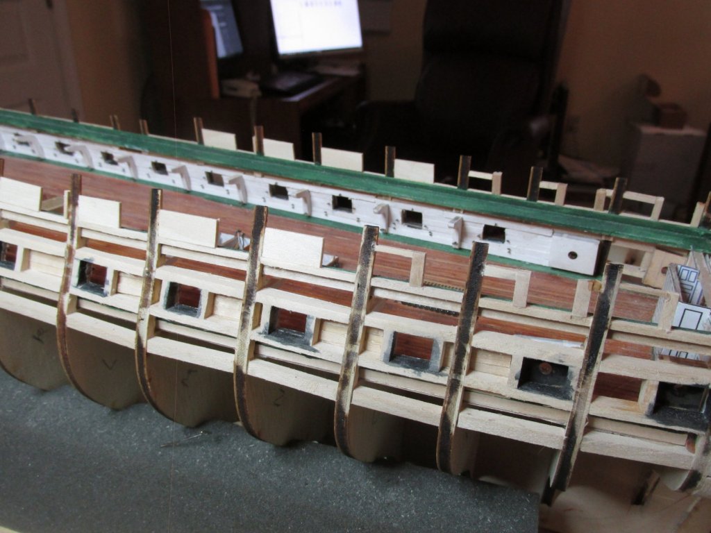
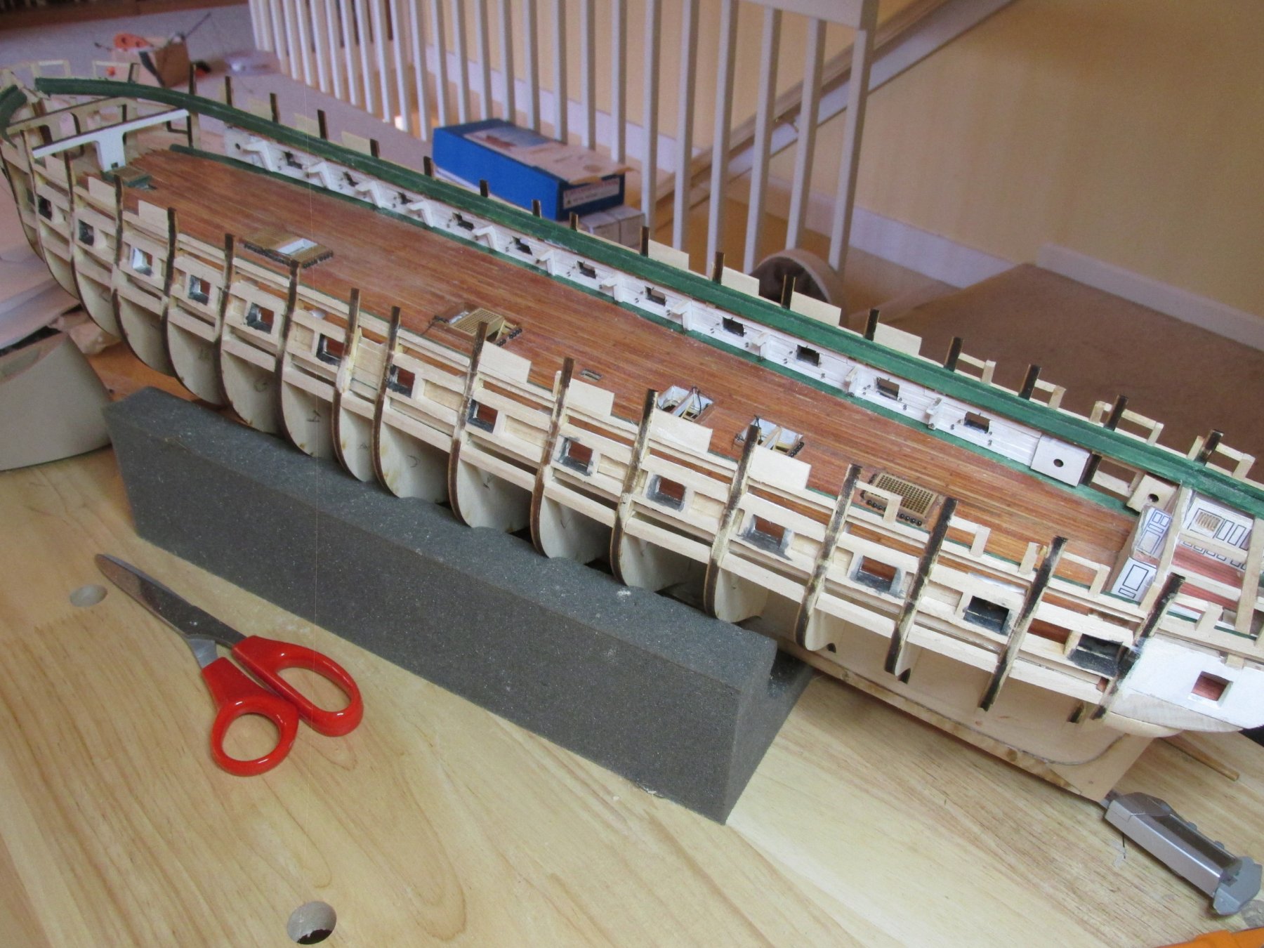
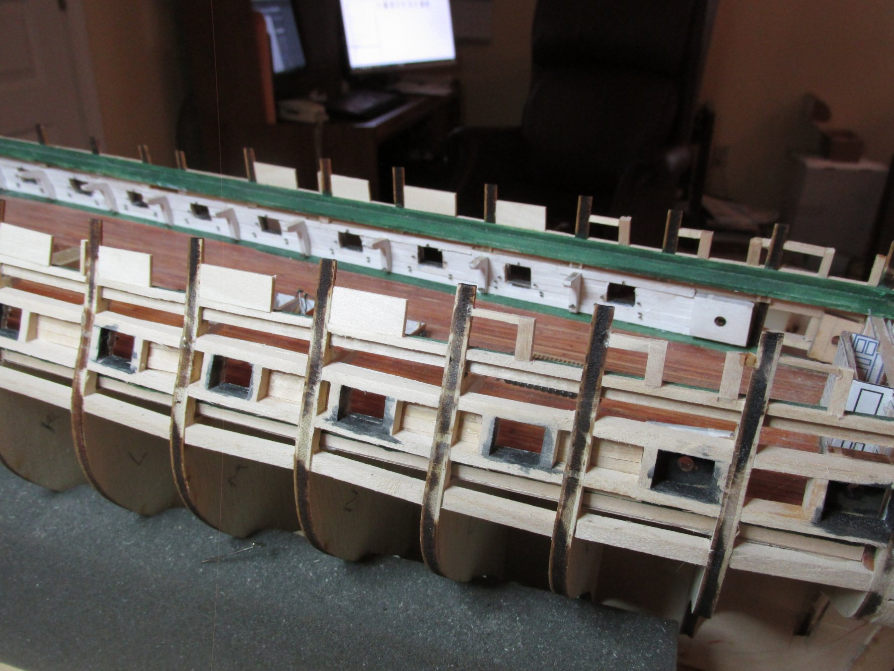
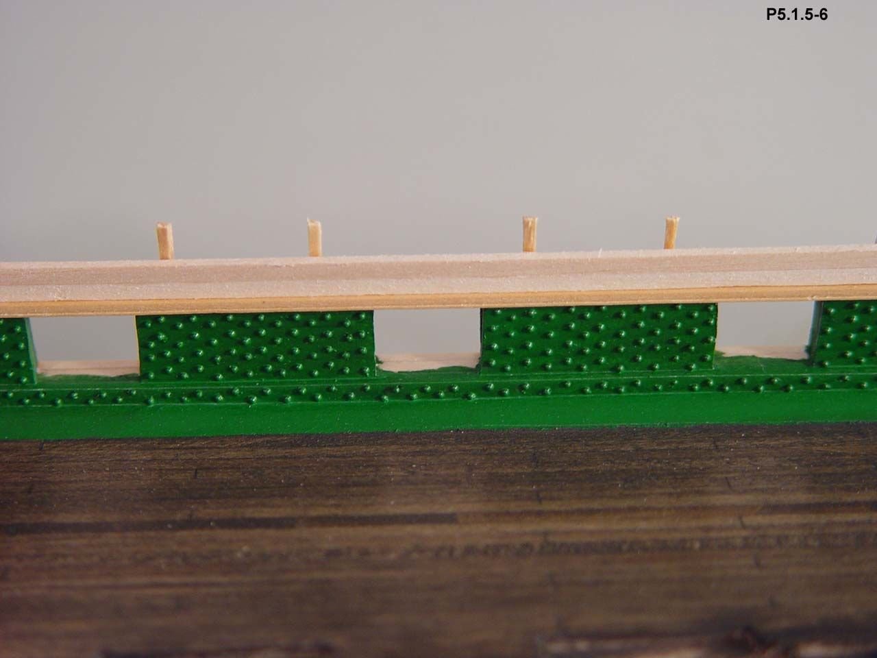
Well after spending time away from the shipyard visiting Mom in Florida, I got back installing the framework for the spar deck bulwarks. As usual, I try to follow the instructions when I can, but it dawned on me that there was an easier way to make these. The top part of the bulkheads is no more than 1/16”. Instead of forming a frame with small pieces and trying to align every, I could a single wide piece of stock basswood 1/16” thick. It was easier, went faster, and seemed to work. You will notice that I was working from the stern, forward and you can see the change.
- poundemin59, CaptainSteve, J11 and 3 others
-
6
-
You make sound so simple
-
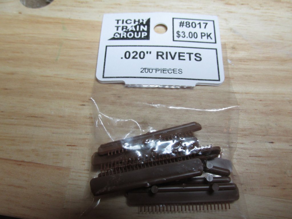
Keith - I did look into the transfer rivets. The main problem I had with them is that they are designed for model railroad use and as a result, the rivet spacing is way too close together. Also, flexibility of use on ship models was limited.
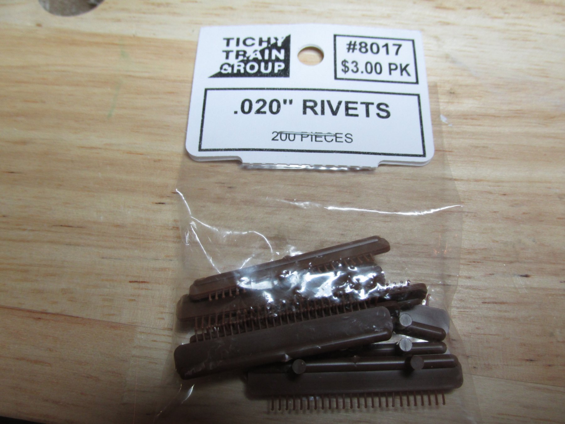
Ken - I was aware of these beautiful mini rivets but not of the MSW members' ability to purchase them in bulk packs of 1000. I saw the posted price of 50 for $6.00, which if other people's estimate of the number bolt heads required as 3000 is correct, that would have meant I needed to lay out $360, hence my brass punch, which cost me around $80.00. One sheet of brass costs $3.50 and I can make thousands of punch-outs. Any idea what the rivet bulk pack cost is?
Thanks for looking in guys, Jon
-
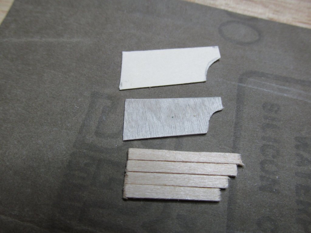
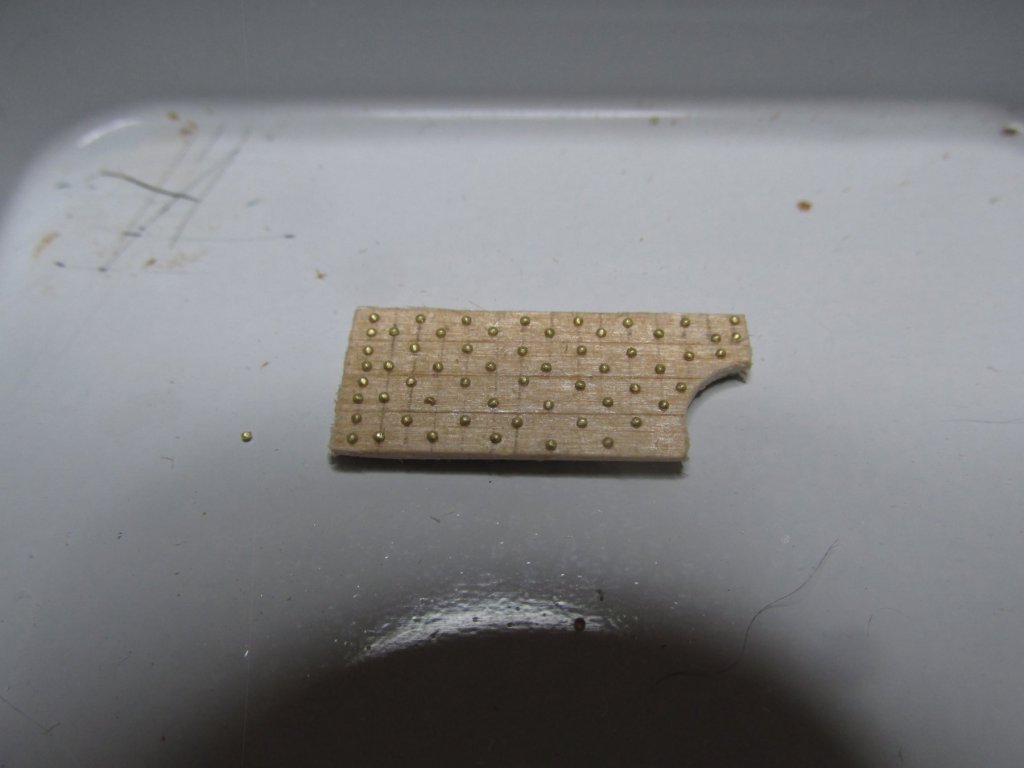
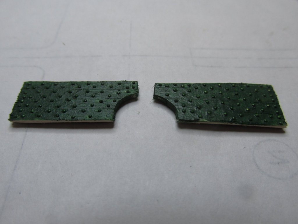
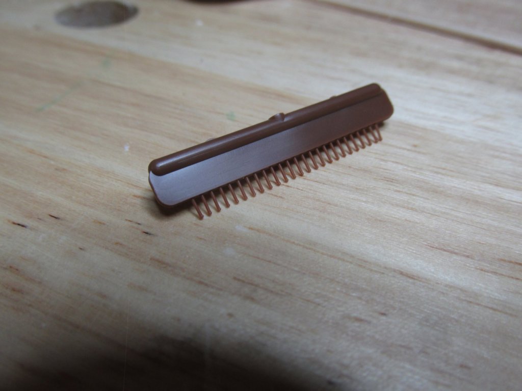
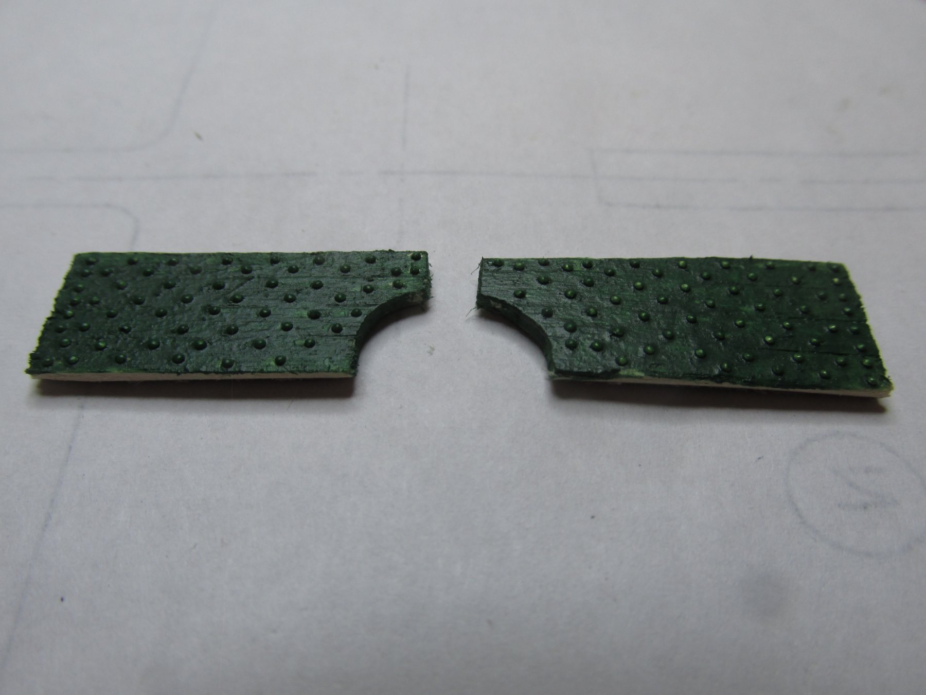
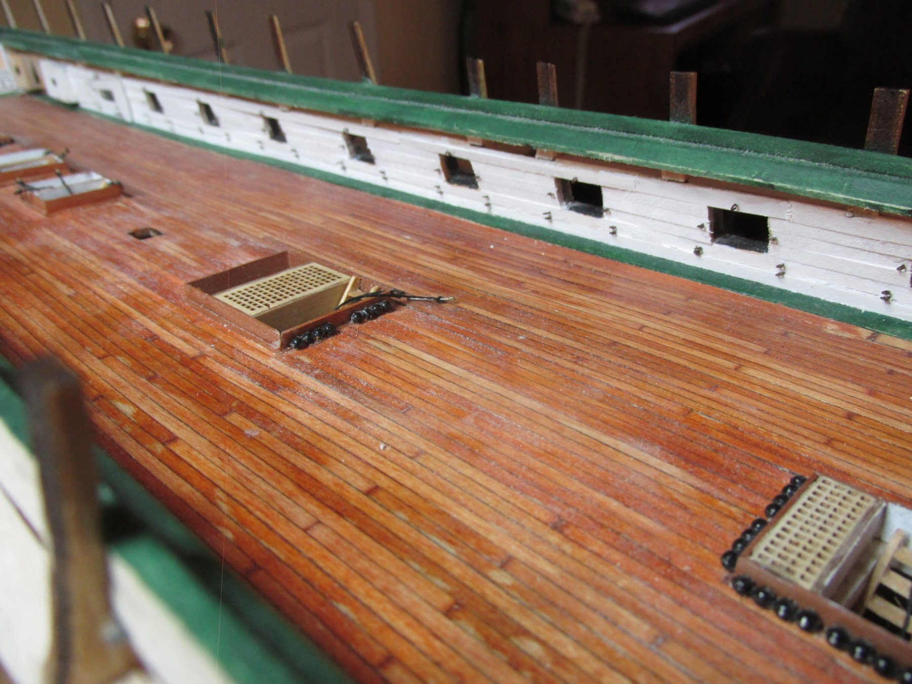
I started with the bulwarks that surround the bowsprit. I made templates out of card stock and transferred the shape to the 1/64” plywood backing. Once the plywood was cut out and fitted to the bow, I glued the planking to the plywood. The plywood was then trimmed. Then I punched out approximately 100 pieces of 0.6 mm brass. The bulwarks were marked with parallel lines 1/16” apart as instructed by the practicum. Using a small brush, Wipe-on Poly was applied in the area where the brass punch-on was to go, The brass punch-outs were placed individually, one by one, into position with the damp brush and X-acto blade. Once the surface of the bulwarks was dry, two coats of Model Shipway Bulwark Green were applied.
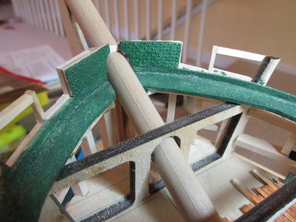
In the last image below, the two bulwarks are dry fitted into position over the partially formed bowsprit. I now plan to frame the remaining gun ports and other openings on the spar deck so that I can continue with the spar deck bulwarks.
- Geoff Matson, BenD, CaptainSteve and 4 others
-
7
-
Installing the bulwarks is another matter. Looking at my gun deck bulwarks, I needed a way to ensure those walls has a smooth for the spar deck as they will be in direct sight of the viewer. Therefore, I plan on using a technique that Mr. Hunt used in his Rattlesnake practicum – a substructure. Some modelers skipped the substructure method and their made their bulwarks directly out of sheet wood made to look like planks. I’m going to use 1/64” plywood as a base and fasten the planks to it. This way I can also make sure all the bolt heads line up the way I want them to. Then I’ll take the sub-assembly and install it onto the model. That’s the plan anyways.
-
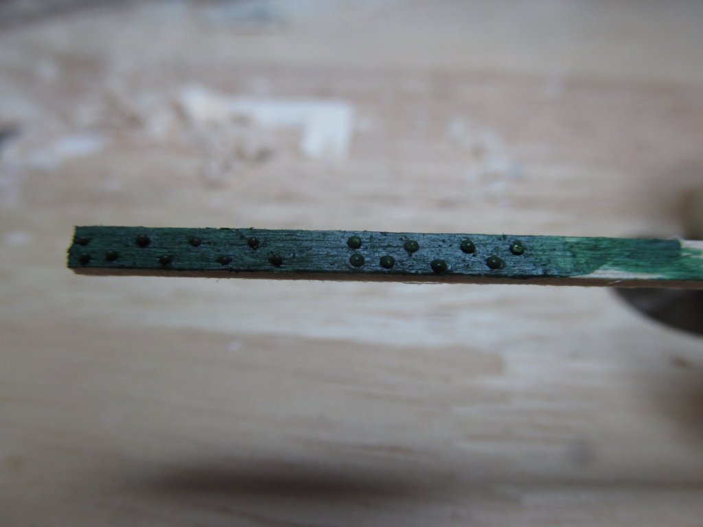
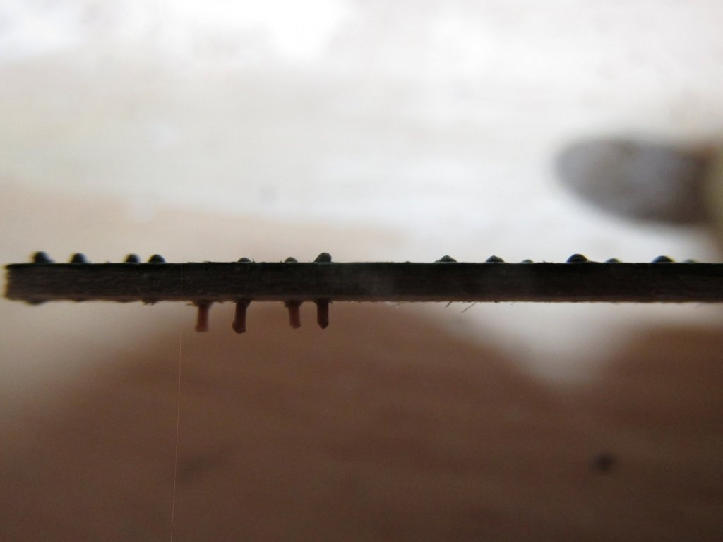
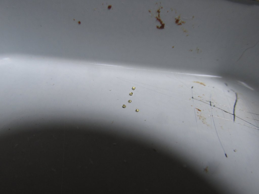
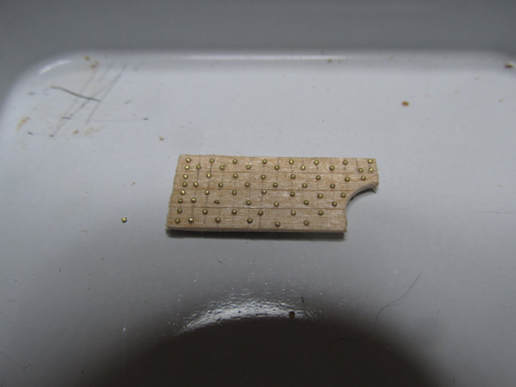
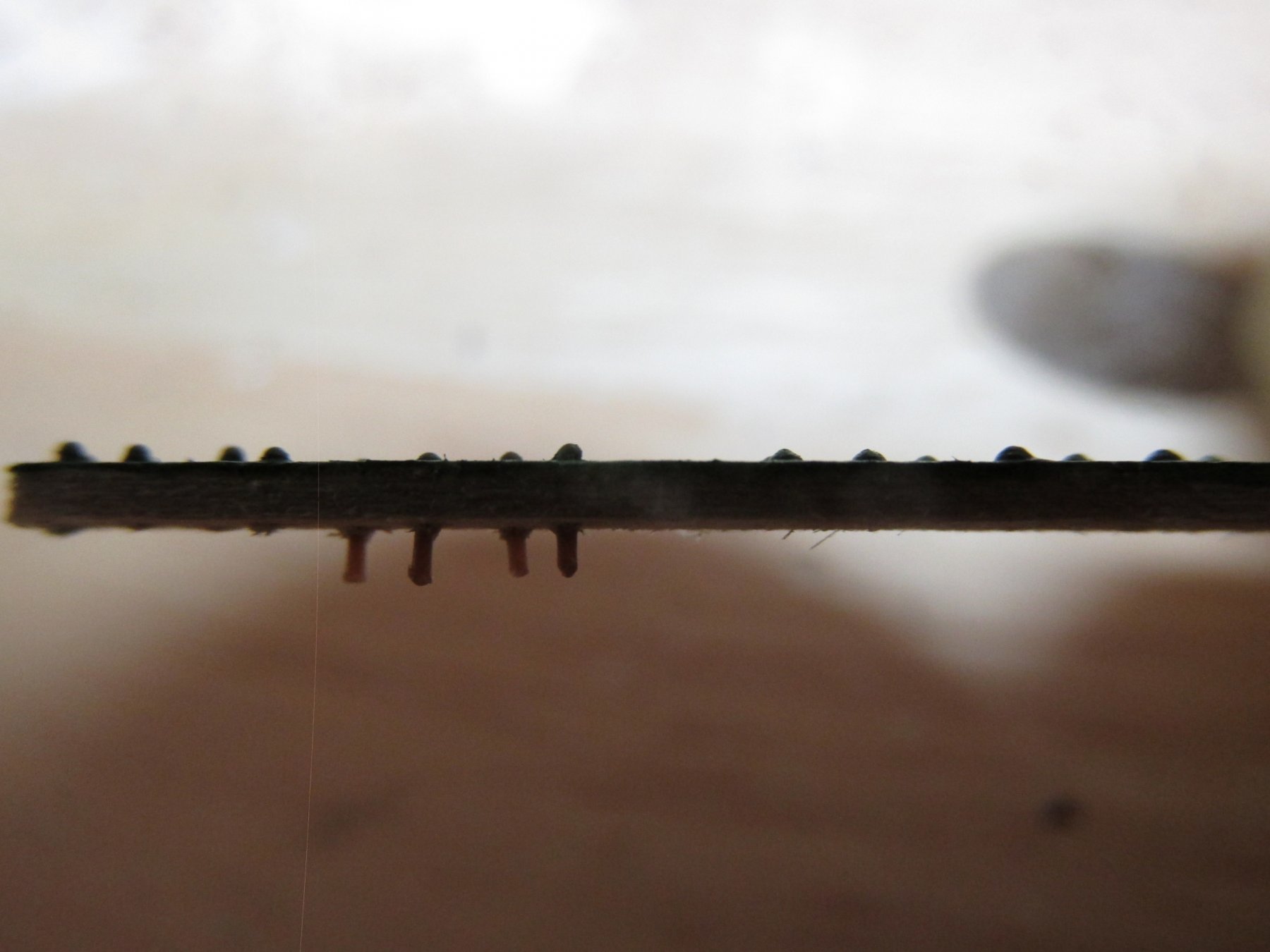
Finally, the surface was painted bulwark green. The paint acted as glue for the plastic rivet and a secondary adhesive for the brass. The results are fairly close, but the brass gave a consistent diameter and height above surface. I am going to start with the brass punch method although I may also use the plastic rivets if the need arises. There is no way I could do this directly on the model. How Mr. Hunt accomplished that feat, is beyond me. In the images below, the left side of the plank are the plastic rivets and the right the brass. I tried showing the height above surface in the second image. Sorry for the poor lighting, but to get these closeups, the camera lens was practically touching the wood blocking my light source. So now I will have to start making over 3,000 pieces of this brass pixy dust. Unfortunately, I still think the results still show the bolt head too high off the surface for both methods, but it’s the best I can do. And to answer your question, yes, I’m out of my frigin’ mind!!
- kmart, Nirvana, CaptainSteve and 1 other
-
4
-
The working surface will be coated with Wipe-on Poly and the punched brass will be picked up and placed on the working surface using a small damp brush. Maneuvering and positioning the punched brass into its final position will be accomplished with the point of an X-acto knife. Still tedious, but at least I can re-adjust the bolt head position if need be. I will very nearly match my initial guesstimate of 1” dia. x 1½” with 1½” dia. x 3/8” bolt heads or so goes the theory.
I made a test plank with both methods. Using the plastic rivets, I had to be very careful how I held them in my tweezers. The point of my tweezers was almost the length of the shaft of the rivet so trying to insert them into the predrilled holes can be very delicate. Sometimes the rivet would shoot off the tweezers if the tweezer points moved the wrong way. There is no point in looking for them because they are so small, they are gone…just gone. For this test, I lost 4 of the 9 I originally started with. I found that I had to use the full length of the rivet shaft to get a proper grip to allow me to push them to the drilled holes.
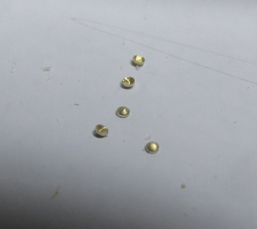
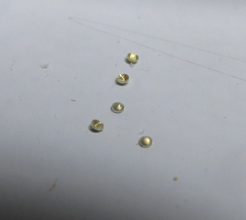
Using the brass, punching out the rivets was very easy but boy are they tiny. There is no way you can pick them up with a tweezer. I thin coated the area I wanted to fasten the bolt heads with Wipe-on Poly and using the same damp brush, I picked up a punch brass piece. Getting the bowl shape so that its convex surface was facing outward was fairly easy, as was positioning.
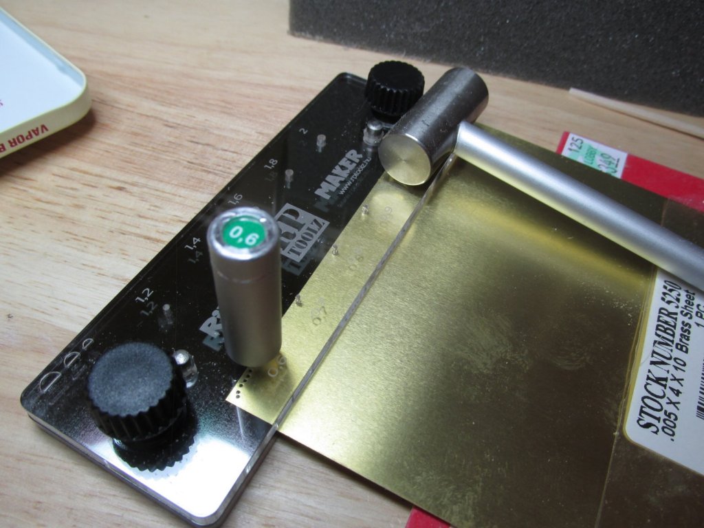
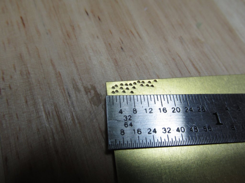
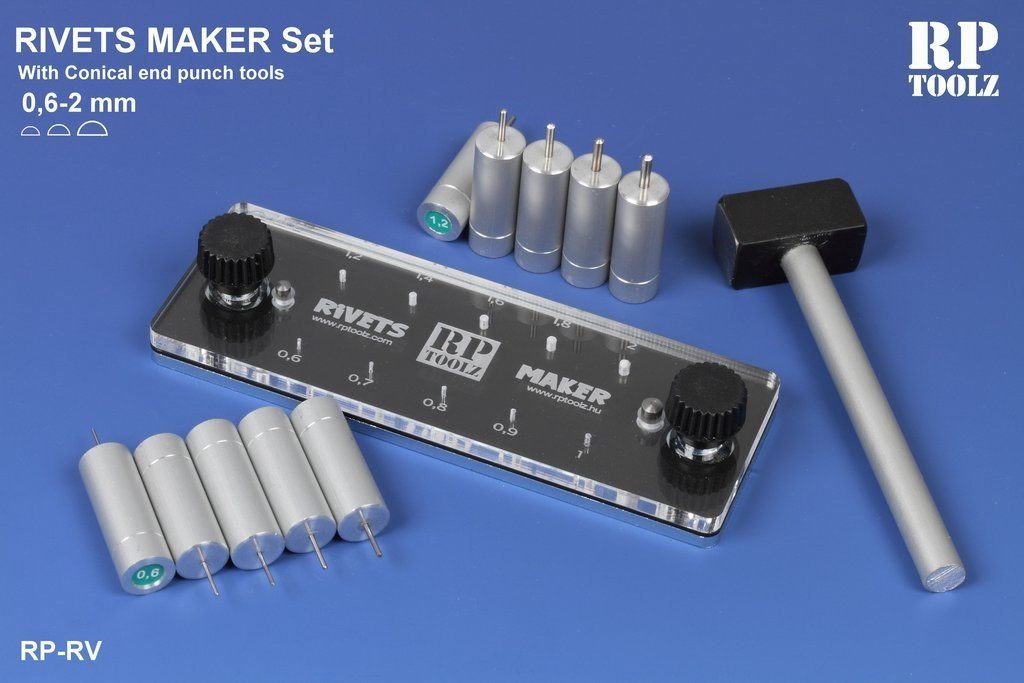
Both processes required the work to be done under magnification. In the images below, is the punch set-up, the brass plate with the punch-out holes, the punched-out brass, and a close-up of the punch-out brass.
-
I ran across a tool, which I hope will solve this problem – a precision punch made by RP Toolz called a Rivet Maker Set which can make a rounded rivet head using 0.06 mm to 2 mm punches. I’ll be using 0.005” brass plate (3/8” equivalent) as the bolt head raw material, and the tool’s smallest punch, the 0.6 mm (0.023”) equivalent to 1½” dia. head. The punch is designed to create a bowl shape punch-out.
-
To install, each rivet shaft must be removed from the spruce tree, making sure they don’t fly away when cut off, and fitted into a hole that must be pre-drilled precisely in the right location. The plastic rivets, due to the nature of the molding process, are not very precise so thickness and shape vary. Mr. Hunt drilled the precision bolt holes directly on his model; a very difficult thing to do and I have no idea how he did that. He did a beautiful job.
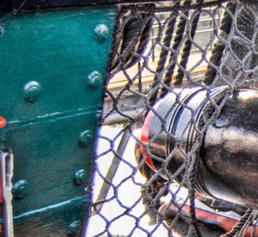
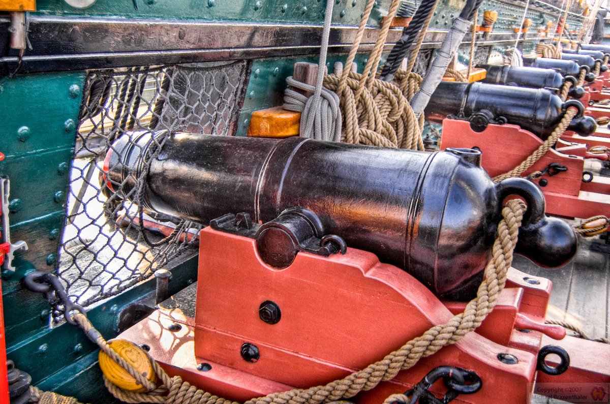
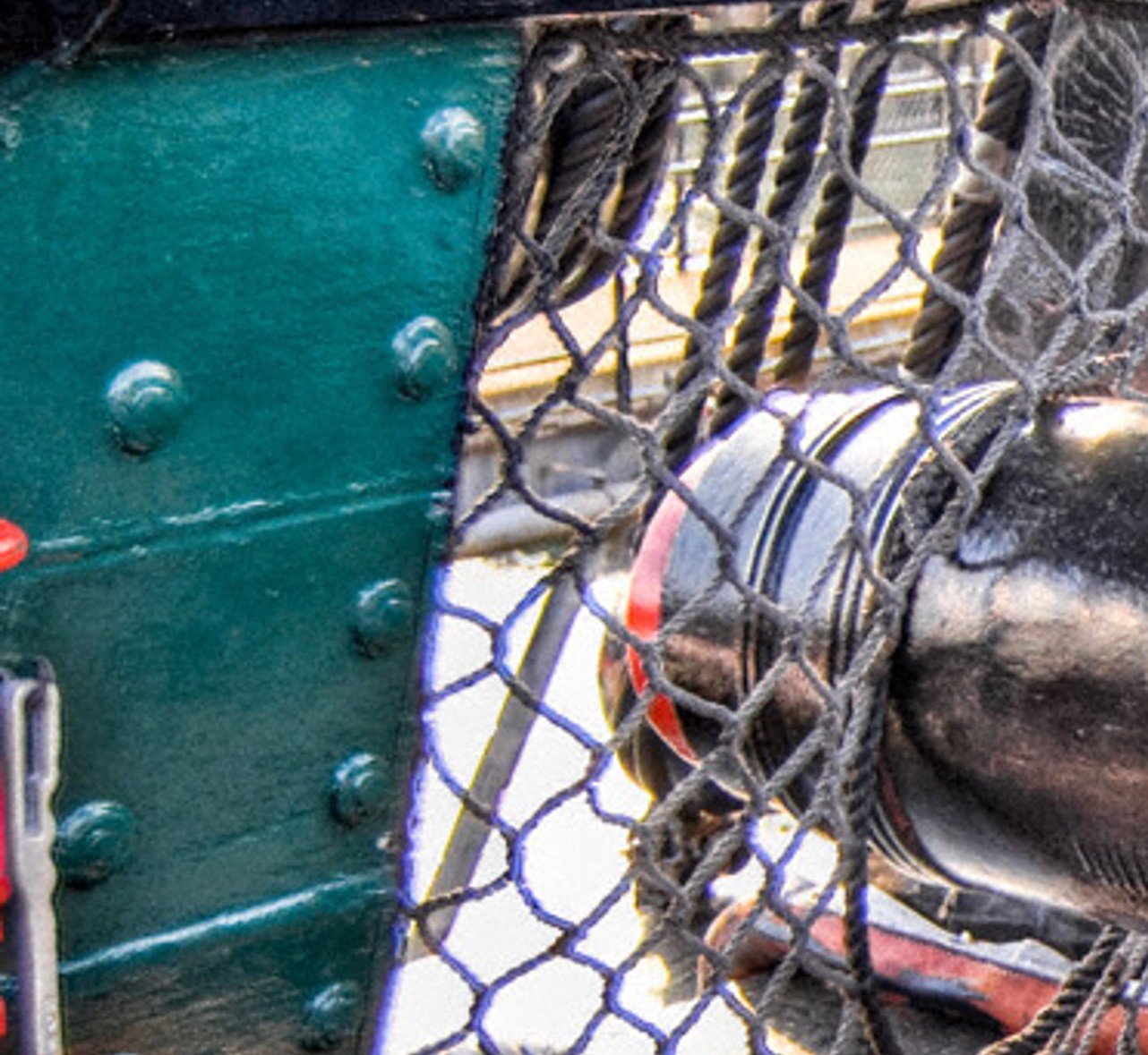
The problem I had with his results, was as neat and pretty as it was, they looked out of scale, i.e., the bolt heads looked too high off the surface of the bulwark, in my humble opinion. Other modelers have attempted this tedious, labor intensive endeavor using his method or other ones. They also had results that looked to me out of scale. Usually the bolt head diameter was too big as well as too high, again in my opinion. Compare the actual with the model.


- CaptainSteve, Geoff Matson and kmart
-
3
-
Robert Hunt in his practicum, added the bolt heads to his model using Tichy Train’s 0.02” (#77 drill size) plastic rivets. The dimensions refer to the rivet shaft. The rivet head diameter and height above surface are not indicated.
-
Spar Deck Bulwarks
One of Murphy’s Laws states: “No matter what you have to do, you have to do something else first.” In order to install the spar deck bulwarks, I must prepare the 3/32” x 3/64” basswood stock as planks. That requires the installation of bolt heads.
Bulwark Bolt Heads (“Rivets”)
The bulwarks, both the gun and spar decks, have their planking fastened with bolts but are commonly referred by many as “rivets.” However, I did not simulate the bolts on the gun deck, again citing too much work for poor viewer visibility. The spar deck is another story. They are very prominent and visible to anyone who has visited the ship.
The bulwark “rivets” are bolt heads with a raised rounded edge washer. Due to repeated painting over the years, the thick paint build-up covered the bolt head and washer merging many of them into a single mound looking like a big rivet. I could not find a source that would give me the dimensions of the diameter of the washer and bolt head combo nor the height they raise above the surface of the bulwarks, so I took a guesstimate of 1” dia. x ½”. At scale, this reduces to 0.013” x 0.0065”. VERY TINY, but because there are so many of them, they are noticeable at least on the spar deck.
-
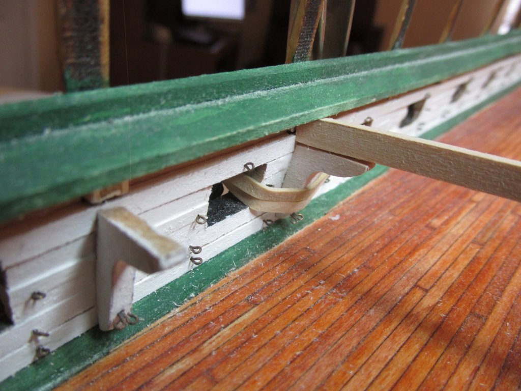
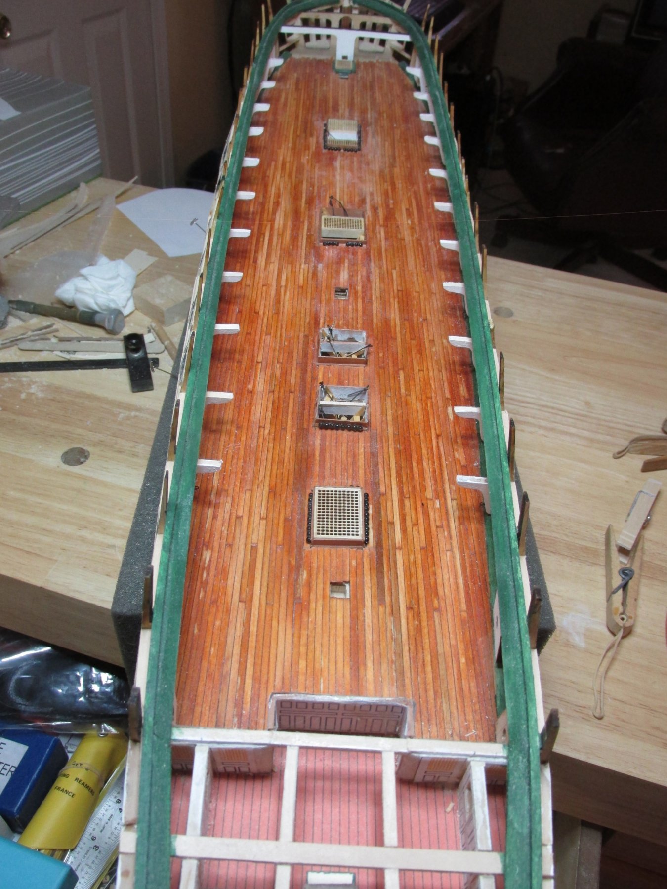
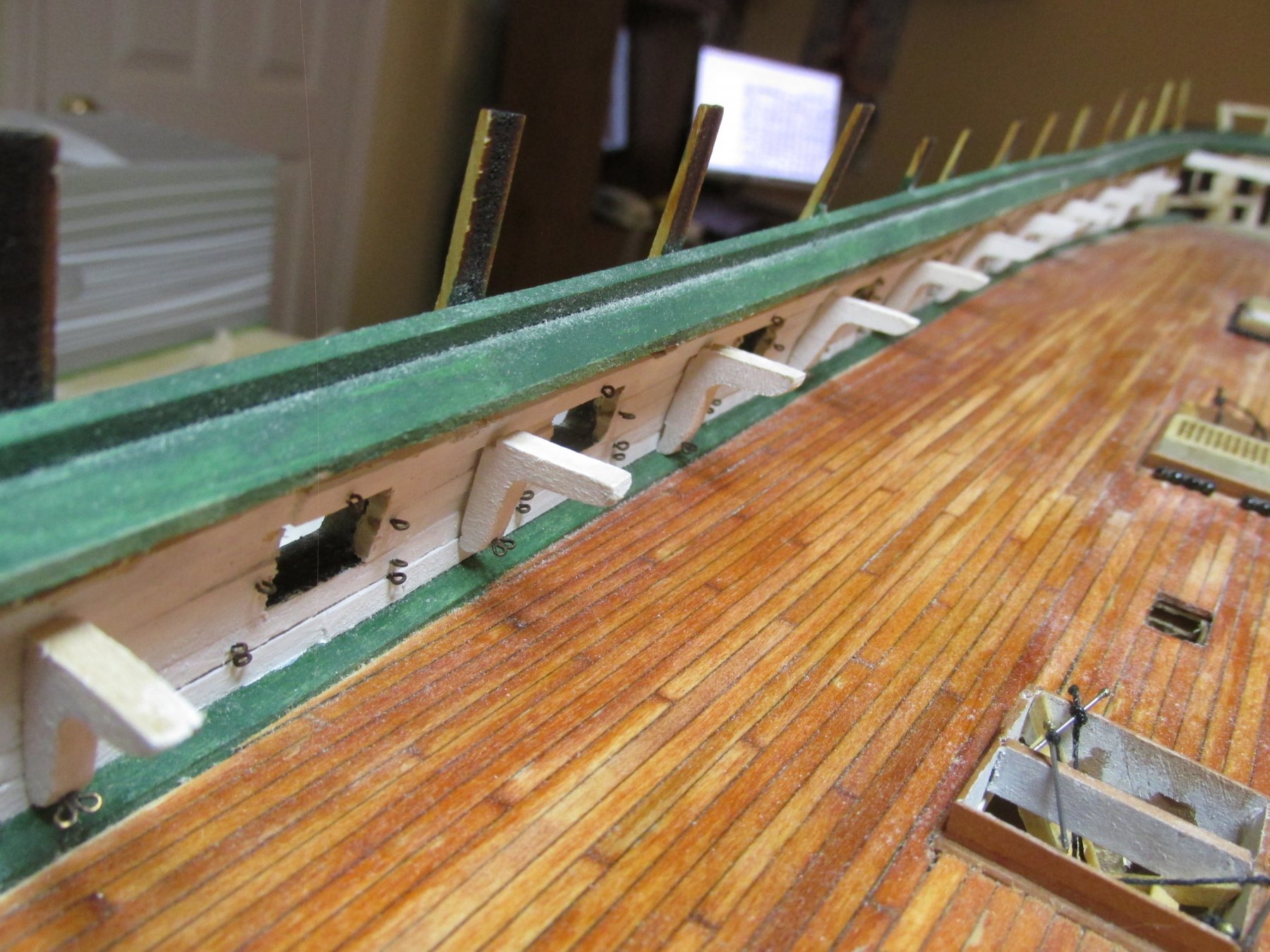
All 22 visible and potentially visible hanging knees with double eyebolts have been constructed, custom fitted to match their individual bulkhead contours, are now installed. Their associated deck beams and the deck beams above the gun ports openings and their associated diagonal knees will installed at a latter date. I still have a bunch of stuff that needs to be install ed on the gun deck and those beams will close off any access if they were to be installed now.
Trying to get back to the practicum, I think building the spar deck bulwarks and caprail should be the next step. Well at least it will strengthen the bulkhead wall extensions so I will stop breaking them


-
-
-
I’ve finally completed installing 154 eyebolts for the gun ports. I had to drill 7 holes per gun port using a push type hand drill: 2 sets of two for the breaching rigging, one eye bolt on either side of the gun port opening, one centered above the gun port opening. All, but the top vertical eyebolt, are orientated horizontally. The 1/16” eyebolts were pre-blackened, trimmed to size, and inserted into the drilled holes. I’ve now started to construct, position, and install the remaining hanging knees.

-
Walker_Wheeler - Considering that the pin stays are located on the gun deck bulwarks, and will be tucked under the spar deck planking, the dark lighting in that area, and the physical size of the hardware, using two eye bolts installed one over the other, no detail of the pin will be visible to the casual observer. The viewer will be looking through openings created in the spar deck where I will be omitting planking for that purpose.
I could have done the something simpler for the double eye bolts located on the the hanging knees, but I wanted to try my hand at silver soldering to see if I could make something that looked like the real thing. I could, so I did. If that didn't work, I was going to use a larger eye bolt so that two hooks could be attached. The layman would not know the difference.
-
-
I decided to take the simple route for the breeching hardware and just used two 1/16” eyebolts. The hard part about this was drilling the holes into the bulkhead. Used tenacity and force of will to do that. That was proof of concept. Now I must do all of this again twice per gun port. Joy.

-
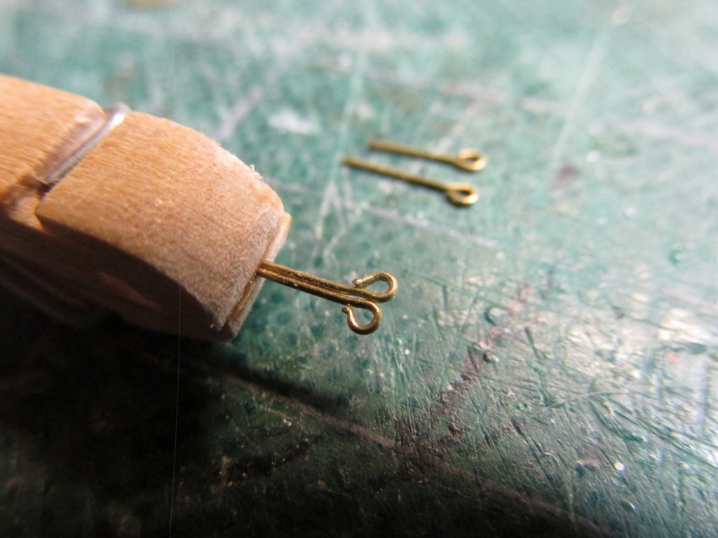
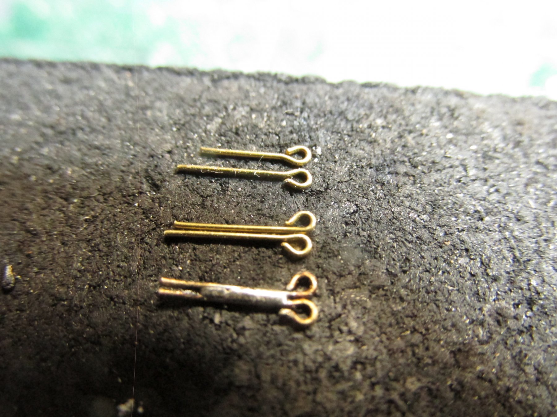
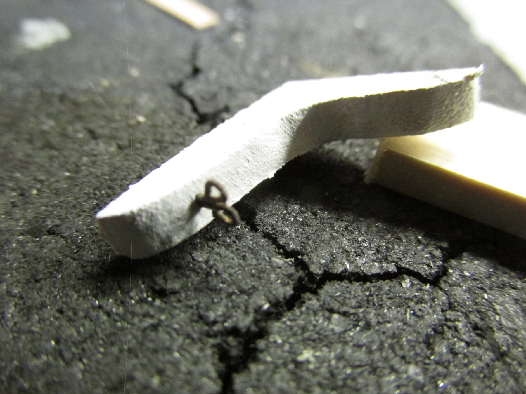
I took it as a challenge to create the double eyebolt, but it really wasn’t too difficult. Using 1/16” eyebolts, I bent the loop such that two eyebolt could lie next to each other without any overlap. These were placed into a slightly modified clothes pin used as a clamp and silver soldered together. I tried using silver solder paste but due to the small and rounded surface area, I could get the paste to stick where I wanted it or well enough. So, I resorted to using flux and a very thin sliver of silver solder from a roll. That worked great. After some filing, trimming, and blackening, I inserted the double eyebolt into the vertical knee.

- usedtosail, tasmanian, CaptainSteve and 2 others
-
5
-
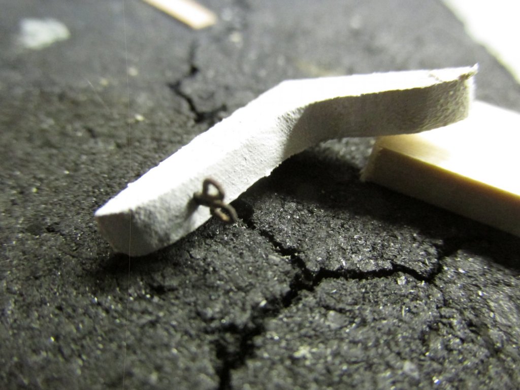
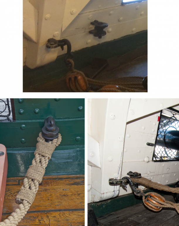
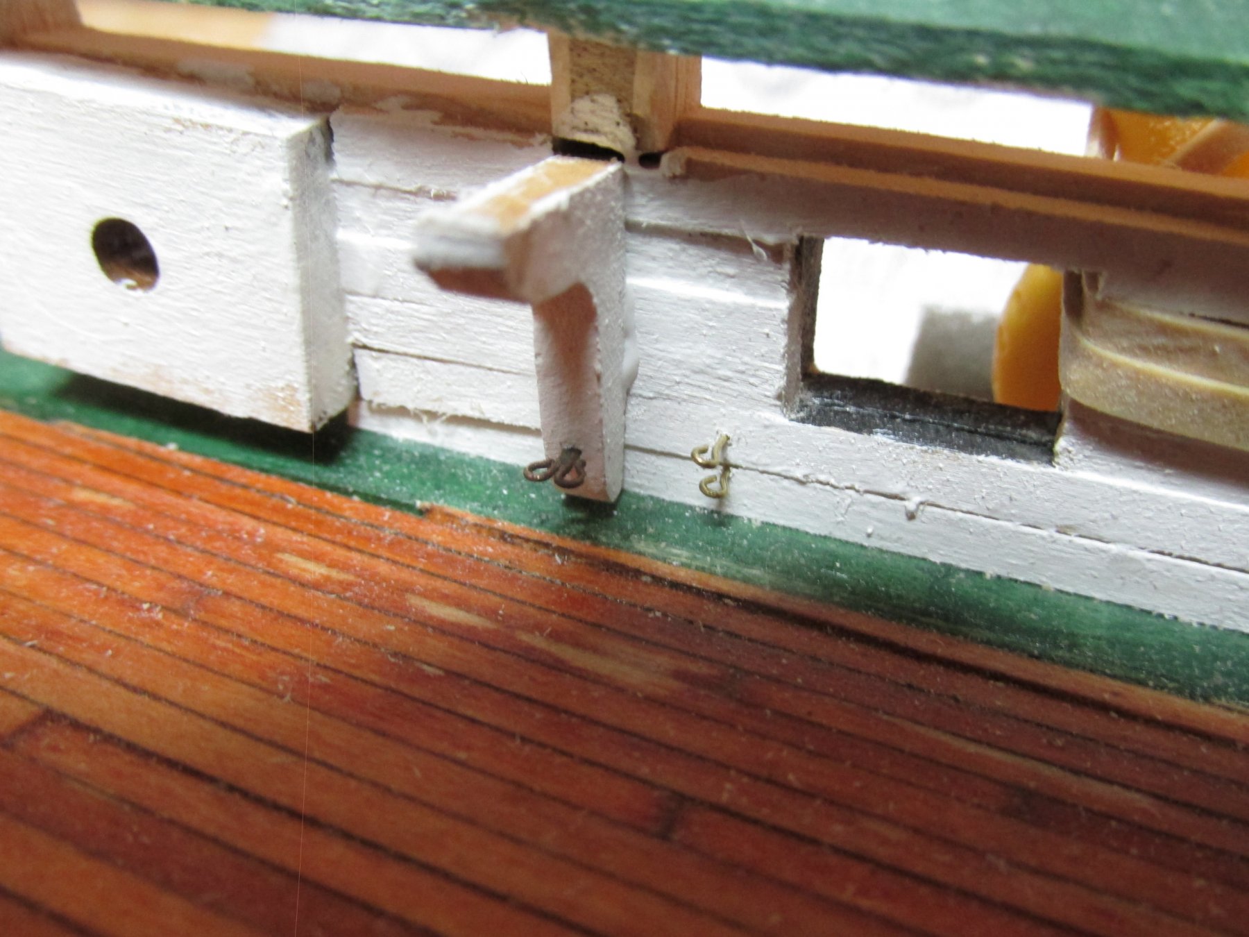
As it turns out, the rigging hardware are not your typical eyebolts. The side tackle of the gun hooks into a double eyebolt while the breeching tackle connects to two rings, one over the other, on the bulwarks using, such a seized loop of thick rope fits between the two rings and is held in place via a pin which drops through the top ring, through the loop of rope, and finally through the bottom ring. It appears the pin has a cap which prevents the pin from dropping all the way through.
- tasmanian and CaptainSteve
-
2
-
The hanging knees for each brace must be custom made as the bulkhead changes angles along the length of the deck. But before any vertical knee is glued into place, the rigging hardware needs to be installed now. To do that latter, would make the task much more difficult.


![1930 - _00_00_ix21_b[1].jpg](https://modelshipworld.com/uploads/monthly_2019_02/839463123_1930-_00_00_ix21_b1.jpg.2d5d35c16f6f5146a4ed3070fc106ecb.jpg)


USS Constitution by JSGerson - Model Shipways Kit No. MS2040
in - Kit build logs for subjects built from 1751 - 1800
Posted
Then, the excess wood was cut away by turning the rudimentary bulwark over and cutting through from the backside of the backing’s cathead opening. Excess wood was filed off the ends of the bulwark and fitted into position to ensure proper fit. The kit supplied cathead was used to fine tune the final shape of the cathead openings. Whether or not I will use the kit supplied catheads, or make my own, remains to be seen at a future date. The rest of the bulwark constructs won’t need extensive bending (I think, I hope).