


JSGerson
-
Posts
2,171 -
Joined
-
Last visited
Content Type
Profiles
Forums
Gallery
Events
Posts posted by JSGerson
-
-
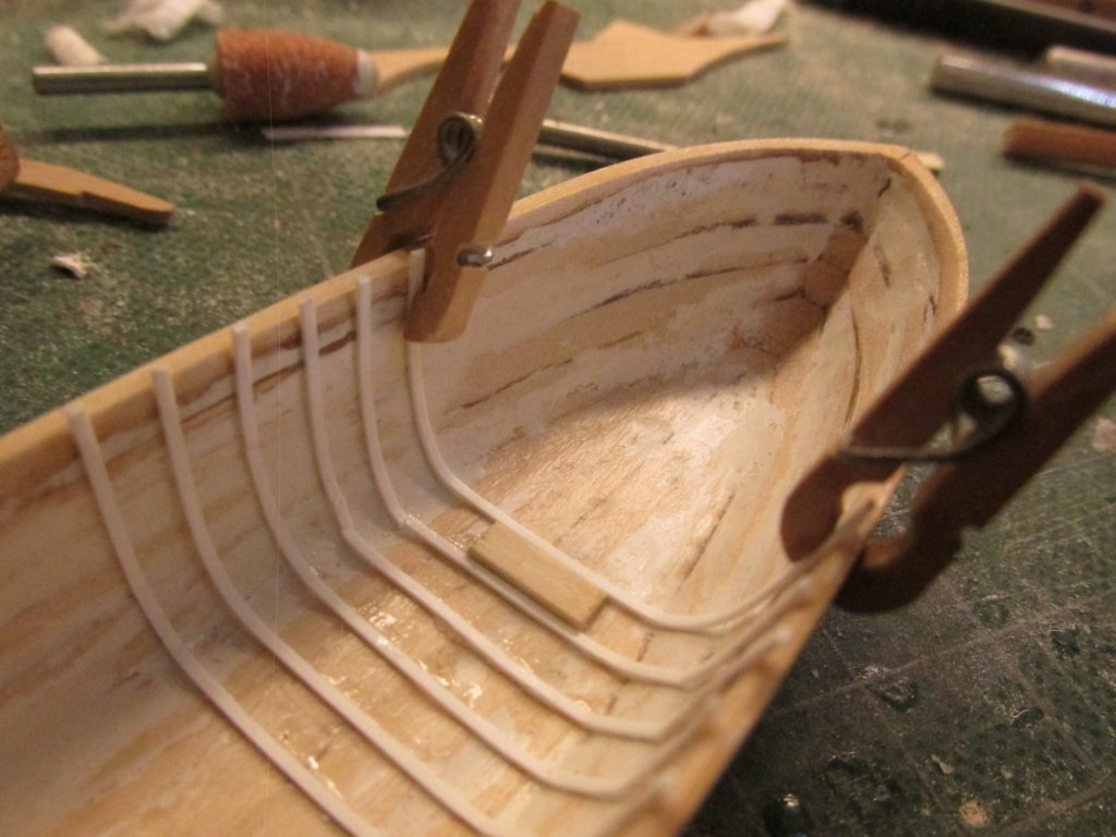
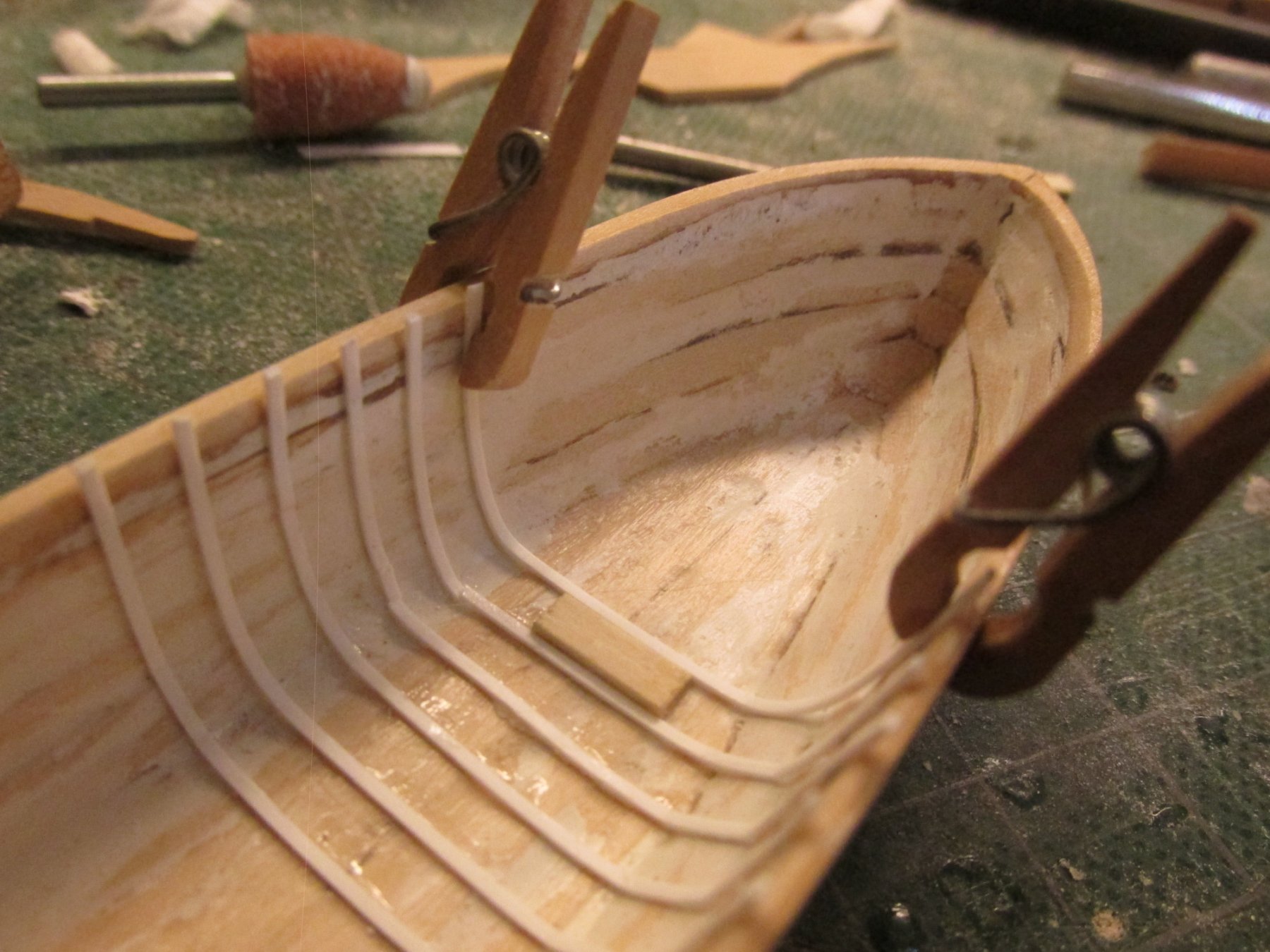
OK, back on course, if pardon the nautical reference. My styrene arrived and I proceeded to start the ribs. Having looked at several build logs, this didn’t appear to be too much trouble to do…riiiggghhht. I started by drawing a center line down the middle of the inside of the boat shell to ensure that when I glued the apron, keelson, and the stern knee, it would be properly positioned. Then I marked the position of the center rib. Using CA glue, I cemented the rib in place a bit at a time. I was using clothes pin clamps and I didn’t want those to get glue on them. When I was done, I saw that the rib had shifted a bit so it was not perpendicular to the center line. This was important because all the other ribs would be position off this rib using a spacer block; so it had to be right. When I tried to lift the rib from the shell with very little pressure with an X-acto blade, it snapped. The CA glue had made the flexible styrene brittle. So when gluing these ribs, they have got to right the first time.
Another thing I noticed while reviewing other build logs where they have documented their ship’s boats construction, is that no two pinnaces were built the same even though MS provides a detailed plan based on the US Navy plans. I can understand when the actual ship and or plans no longer exists so the builder has a lot of room for interpertation. Well, I guess I will find out why as I progress through the construction of this beautiful little craft.
Following the construction process of the practicum, I used a “spacer” to maintain the separation of the ribs as each one was glued into place.
-
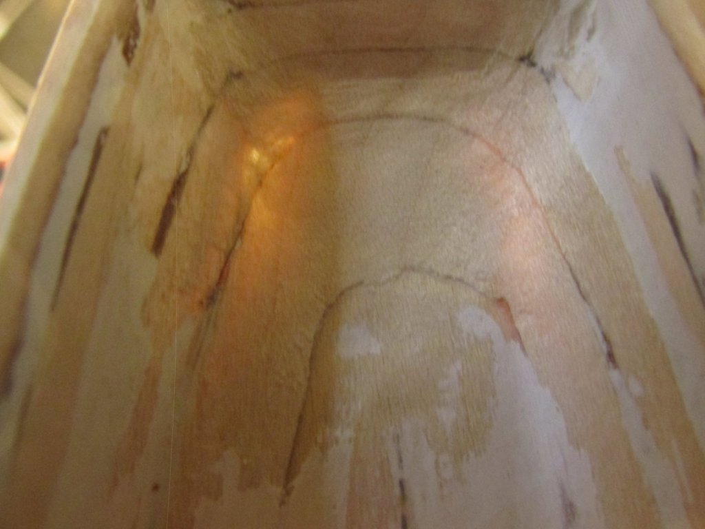
I got out the rotary tool and put the sanding drum on it and sanded down the stern to match the plans, added more filler to smooth out the minor imperfections, and then applied the three coats of Minwax Polycrylic to the newly exposed wood again.
- Geoff Matson, KenW, Bill Morrison and 2 others
-
 5
5
-
Those ratlines look gorgeous!
A few questions if I may: Are you using the line that came with the kit or an outside supplier (e.g., Syren). Also, are the sizes of stay and ratline lines as dictated by the kit's instructions or are you going by some other source? Details, alway love the details 8-)
Jon
- xken, CaptainSteve, Canute and 1 other
-
4
-
That's one handsome looking model!
- Ryland Craze and EJ_L
-
2
-
I'm always curious as to how everyone makes their ladders since they have been a bane for me. Yours caught my eye because I've never seen one done quite that way - notched in back. Now I don't want to be a critic, but the steps appear to be 90 degrees to the side rails. Since the ladder is being used at an angle, shouldn't the steps be at angle also so that they are level? Love your work by the way.
Jon
-
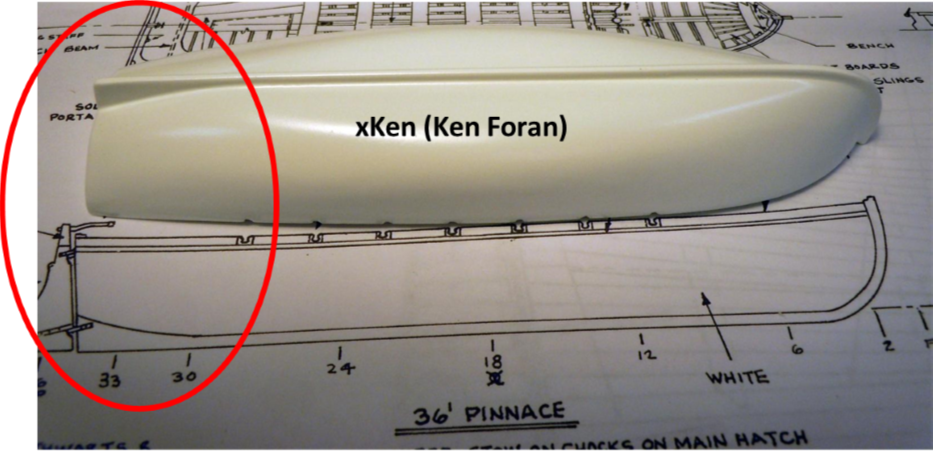
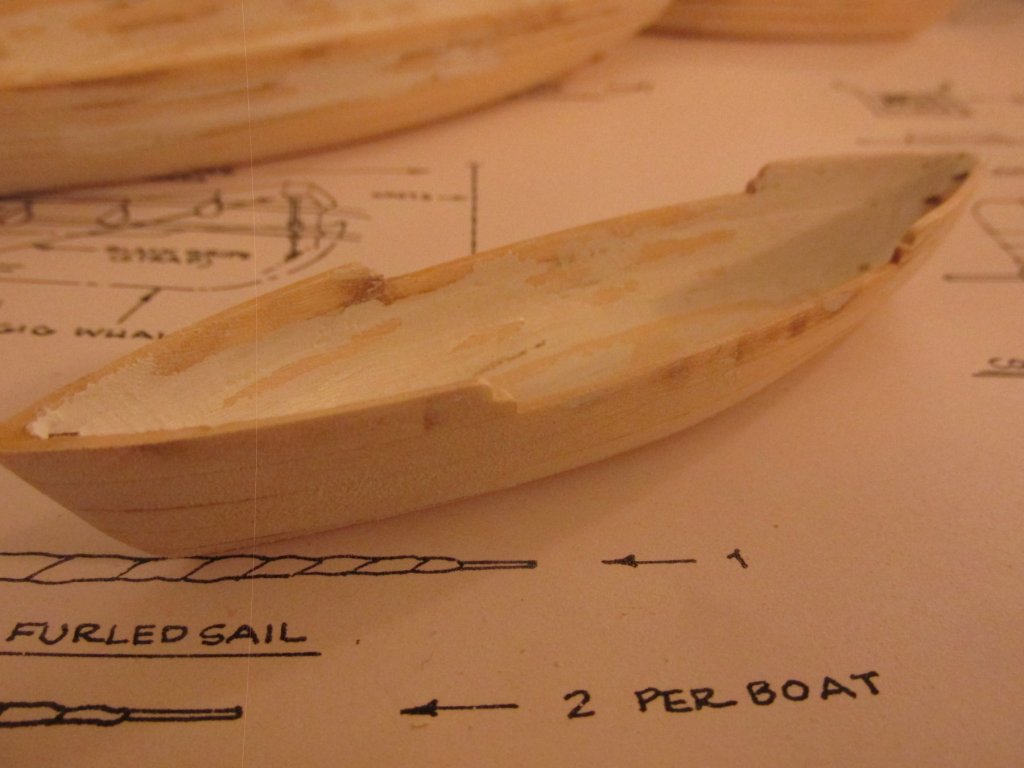
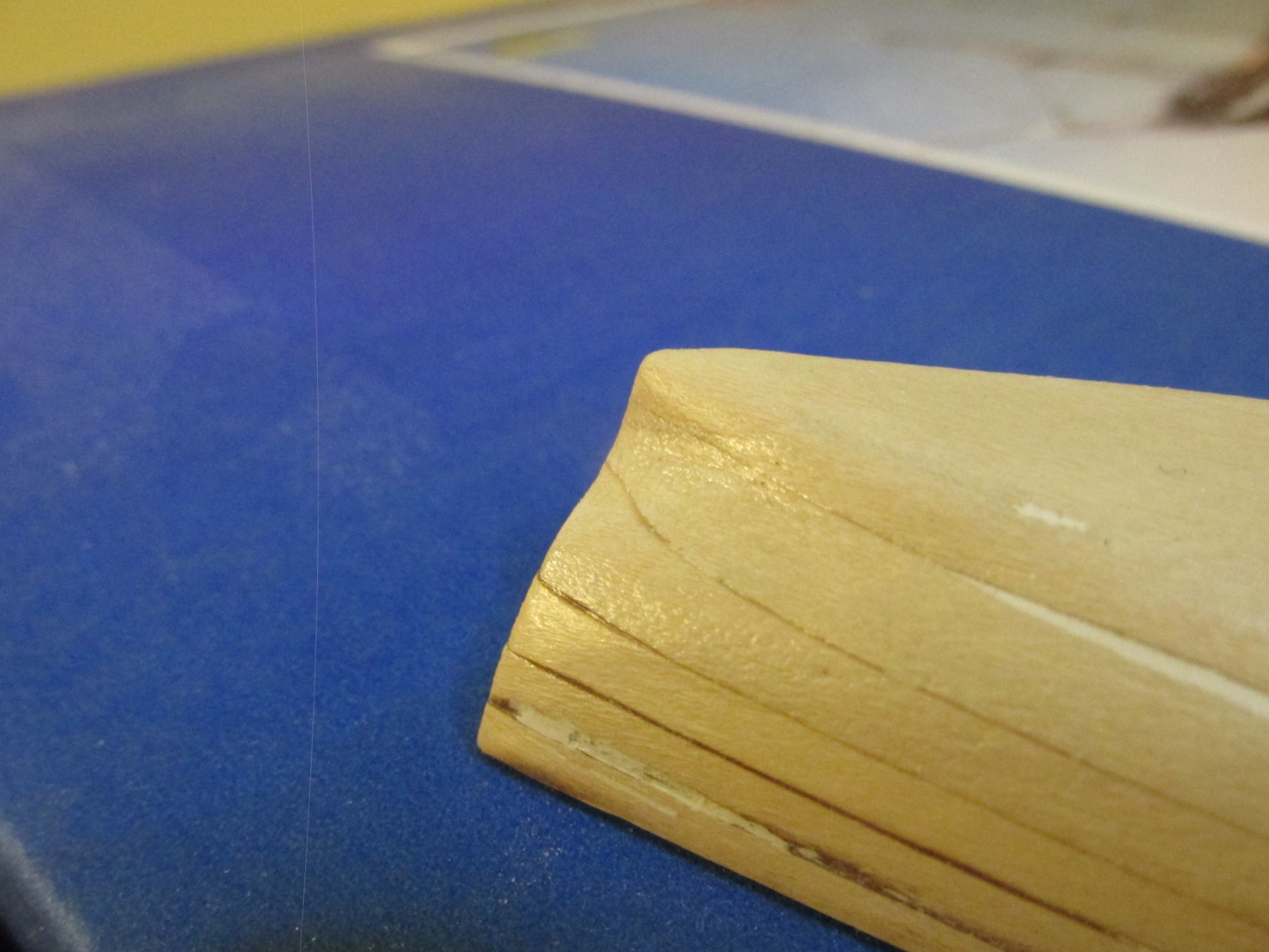
Moving on, I thought I would make the stem and keel parts while still waiting for the styrene strips. It was at this point that my good feeling sank a bit. Looking at the practicum, my pinnace shell looked very similar to what was shown. However, when I looked at the plans to make the templates for the keel and stem I found another problem. The aft end of the boat angled up. See the pictures below. I checked other build logs and those with images of the pinnace that showed the bottom of the boat, all agreed with the plans, not the practicum. So, I have a bit more carving to do. In case you haven’t noticed, I’m still a novice when it comes to reading ship lines on plans.

- CaptainSteve, zoly99sask, kier and 6 others
-
9
-
I checked the contour again and it was very close to what the plans required, so I cut out the knee and apron with my 40-year-old Dremel scroll saw. One of these days I’m going to get a new one that doesn’t vibrate so much and is a lot quieter. With a few minor adjustments with a file, they fit!!! I felt a whole lot better now that it was done right
- zoly99sask, CaptainSteve, WackoWolf and 5 others
-
8
-
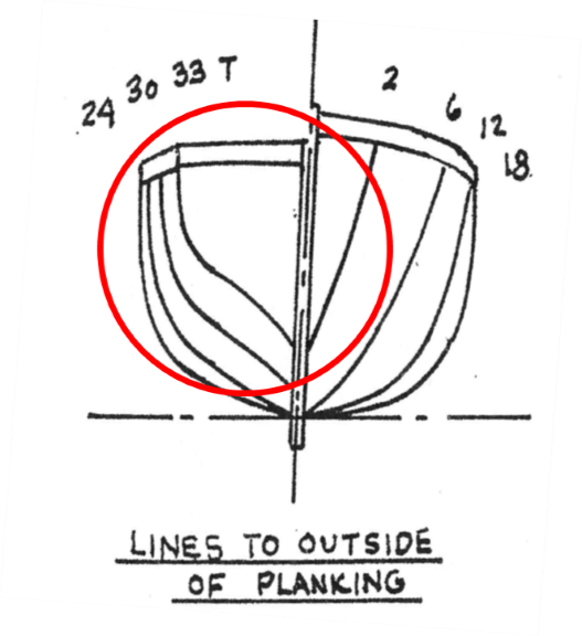
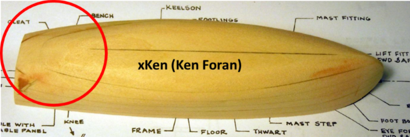
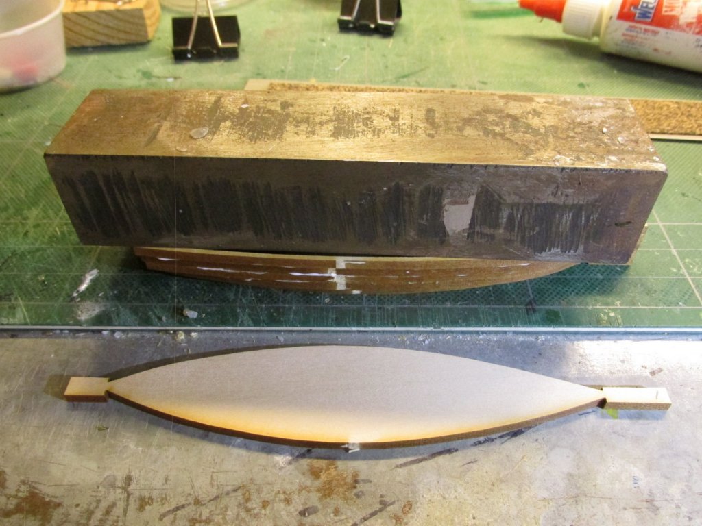
Looking at the pieces to be cut, I began to wonder if they (especially the knee) would even fit on my boat shell. Using a contour gage, I took the profile of the transom. Not only did my transom not match the plans, it wasn’t even close. My boat transom contour better matched the outer surface of the knee than anything. I needed to remove more material in the bottom corner where the knee was supposed to fit.
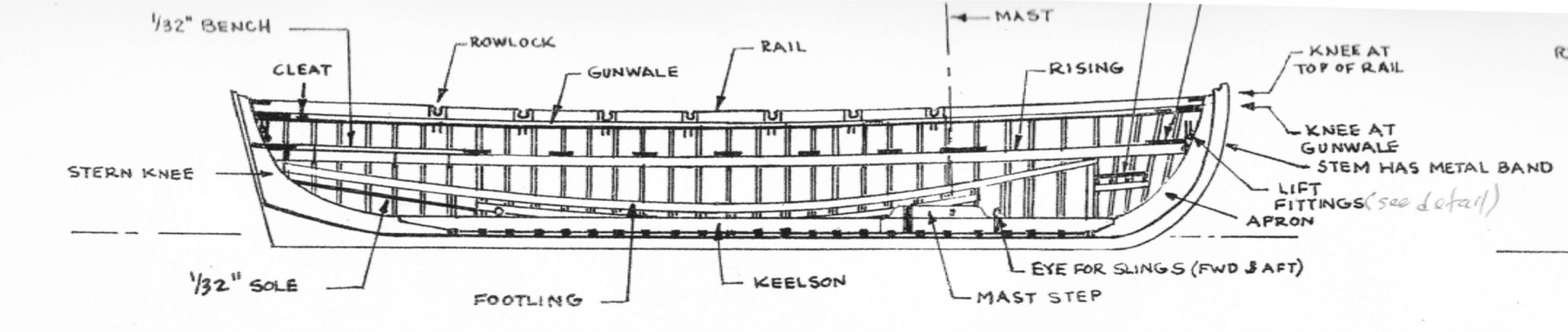
If you look at the boat’s plan above, it shows the transom to be 1/32” thick. That is paper thin if you carving it, which I was. The only way I could achieve that thickness would be to slice off the transom and rebuild it with 1/32” planks. My Byrnes saw can only cut at best 1” thick pieces. I wouldn’t attempt this with a hand saw even if I had one. Due to the confined space in the bottom corner of the transom, as best I could, I removed as much material as I dared using my rotary drill. I used a ball cutter for the wholesale removal and various shaped diamond tipped metal grinding heads for finer removal. The grinding heads removed material slowly for better control. Putting the shell up to the light, I could almost look right through the wall. Bob Hunt in his practicum actually wore right through his boat and had to make repairs.
-
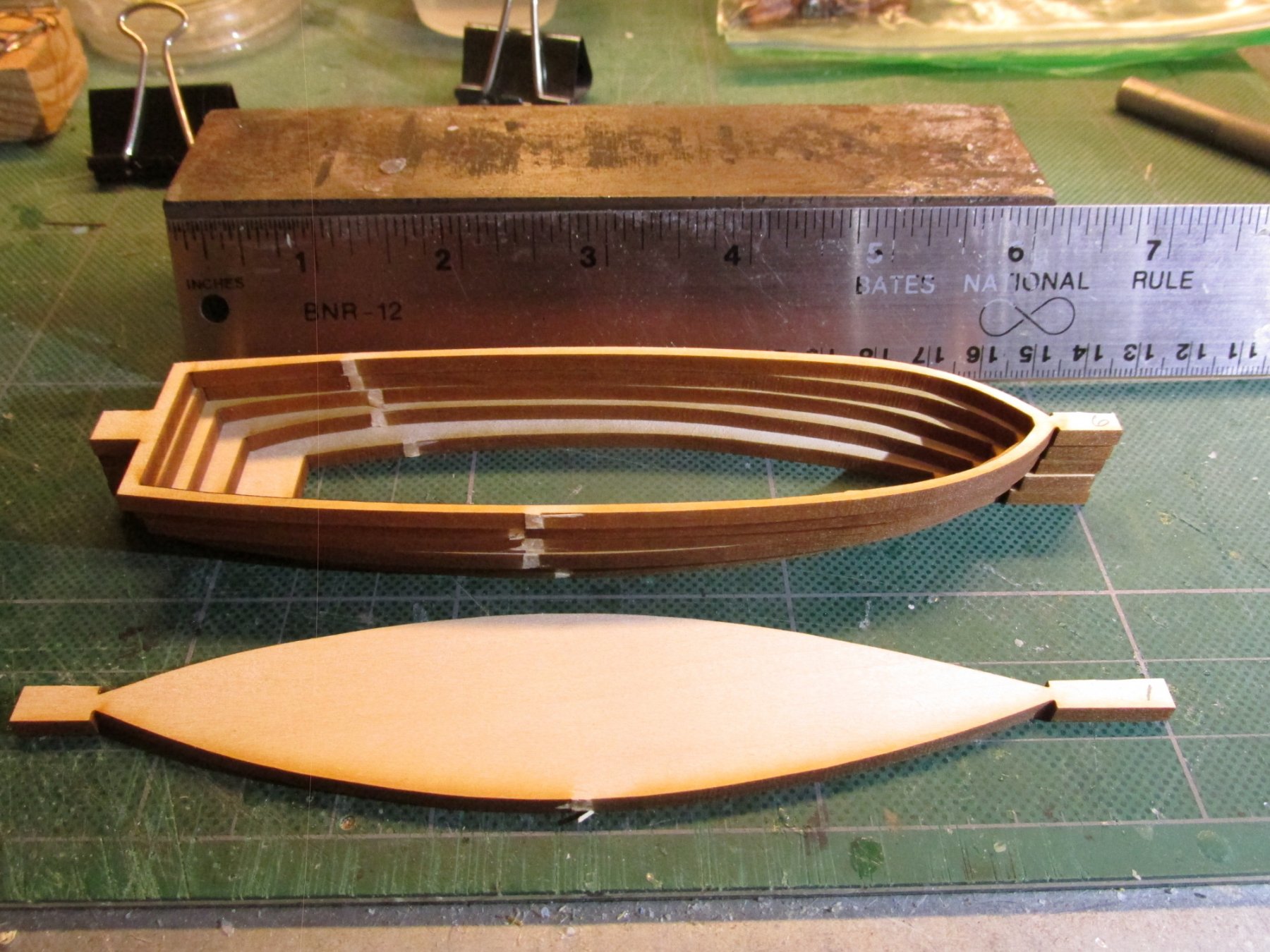
Once the shells were sanded, 3 coats of Minwax Polycrylic were applied with fine sanding in between. The next step was to add the frame ribs. Starting with the Pinnace, the kit calls for 1/64” 1/32” (0.016” x 0.031”) stock material. Bob Hunt in his practicum chose not to use wood, but substitute Evergreen 020" x .040" styrene strips styrene strips (Evergreen No. 122) because “they bend easily to conform to the interior shape of the boat.” Since these parts are going to painted, struggling to bend the wood made no sense, I agreed with him.
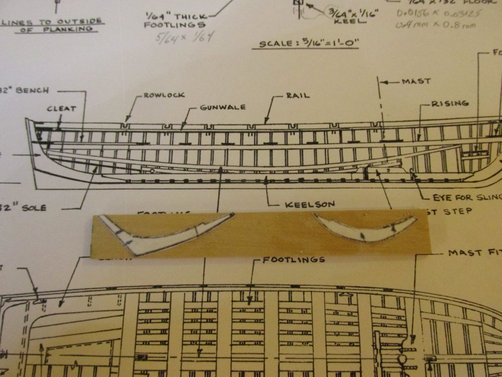
I did not have any styrene strips in stock however; I had to order some. Looking at the Pinnace plans, I noticed that the boat’s stern knee and apron (like an interior stem) are mount directly to the boat’s shell whereas the Keelson rests on top of the frame ribs. Therefore, I could move ahead and install those or at least make the parts while waiting for the styrene…or so went the theory.
I made a copy of the profile plan of the pinnace to use as a template to cut out the shape from 1/16” x 5/64” boxwood (my choice of material) since I like it a lot better than the kit’s basswood. It’s a hardwood and holds an edge much better than basswood. I cut out the knee and apron templates and rubber cemented them onto the stock boxwood (left over from my Rattlesnake).
- KenW, WackoWolf, zoly99sask and 4 others
-
7
-
-
-
I also made my Rattlesnake's euphroe with a Dremel clone rotary drill. I had the advantage of a Dremel drill press stand for their drill plus an X-Y table which allowed me to measure the exact fine spacing between the holes by the number of turns on the crank. The drill press rig ensured that the holes were all perpendicular. From what I can see, you did a very nice job.
Jon
-
I like it! It sure beats my hand cranked version seizing machine.
- CaptainSteve, xken, mtaylor and 1 other
-
4
-
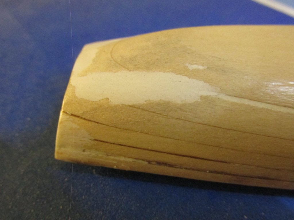
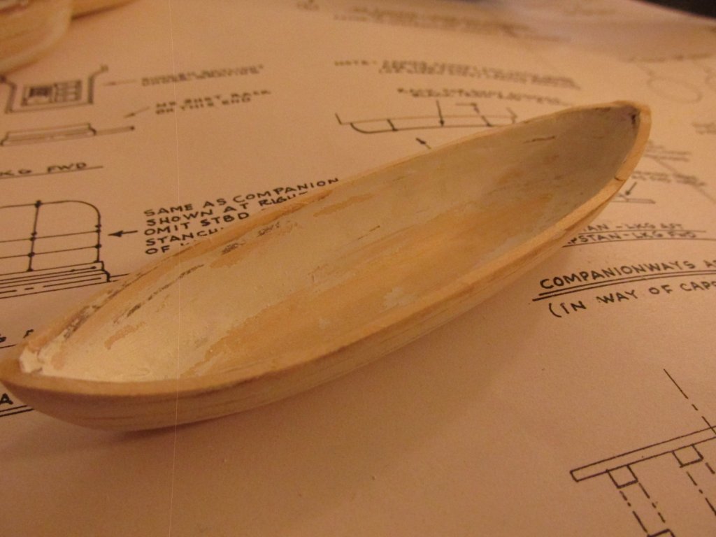
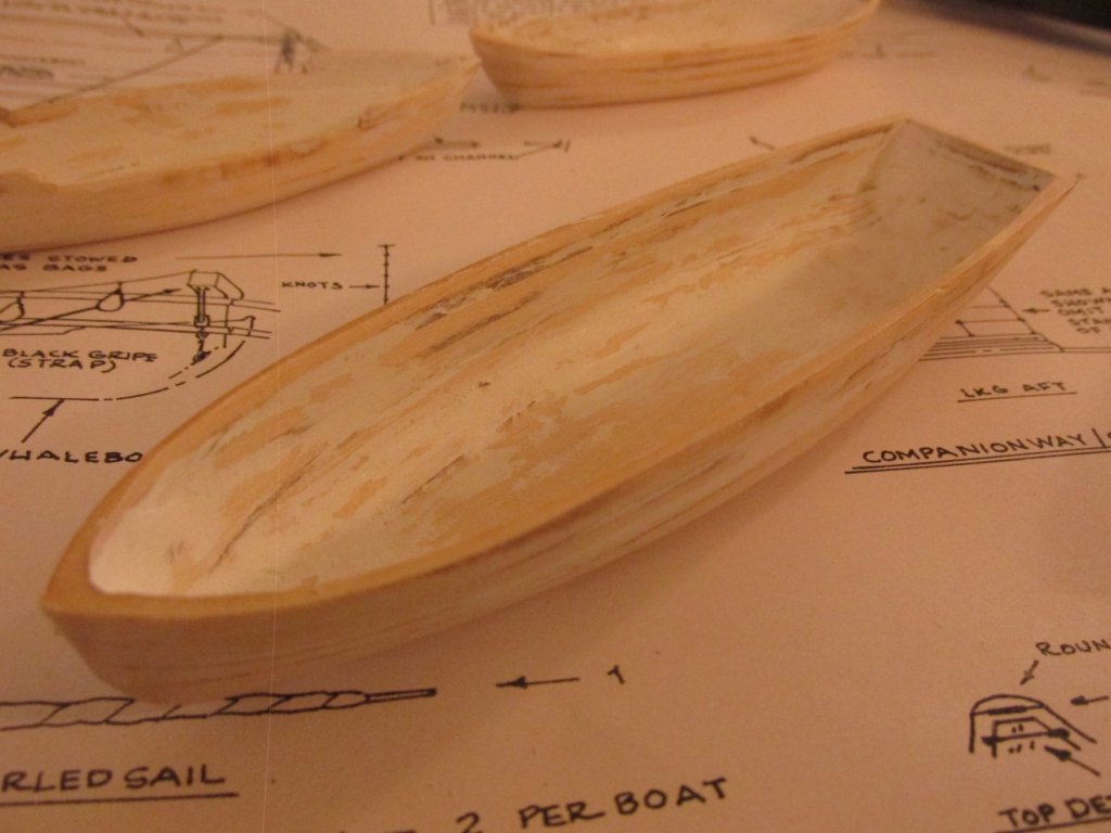
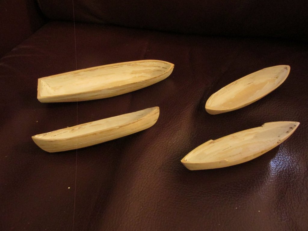
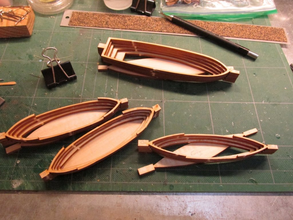
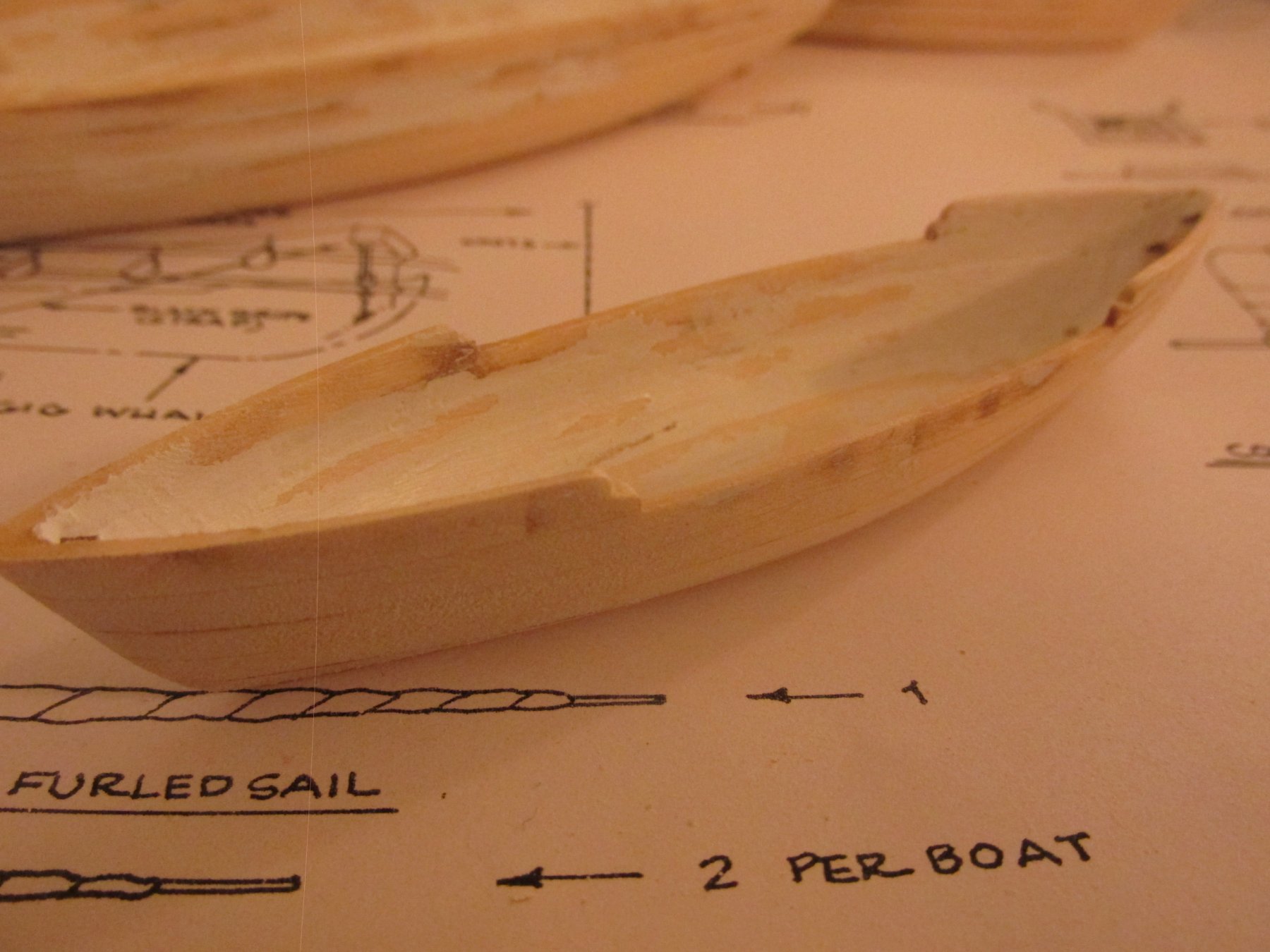
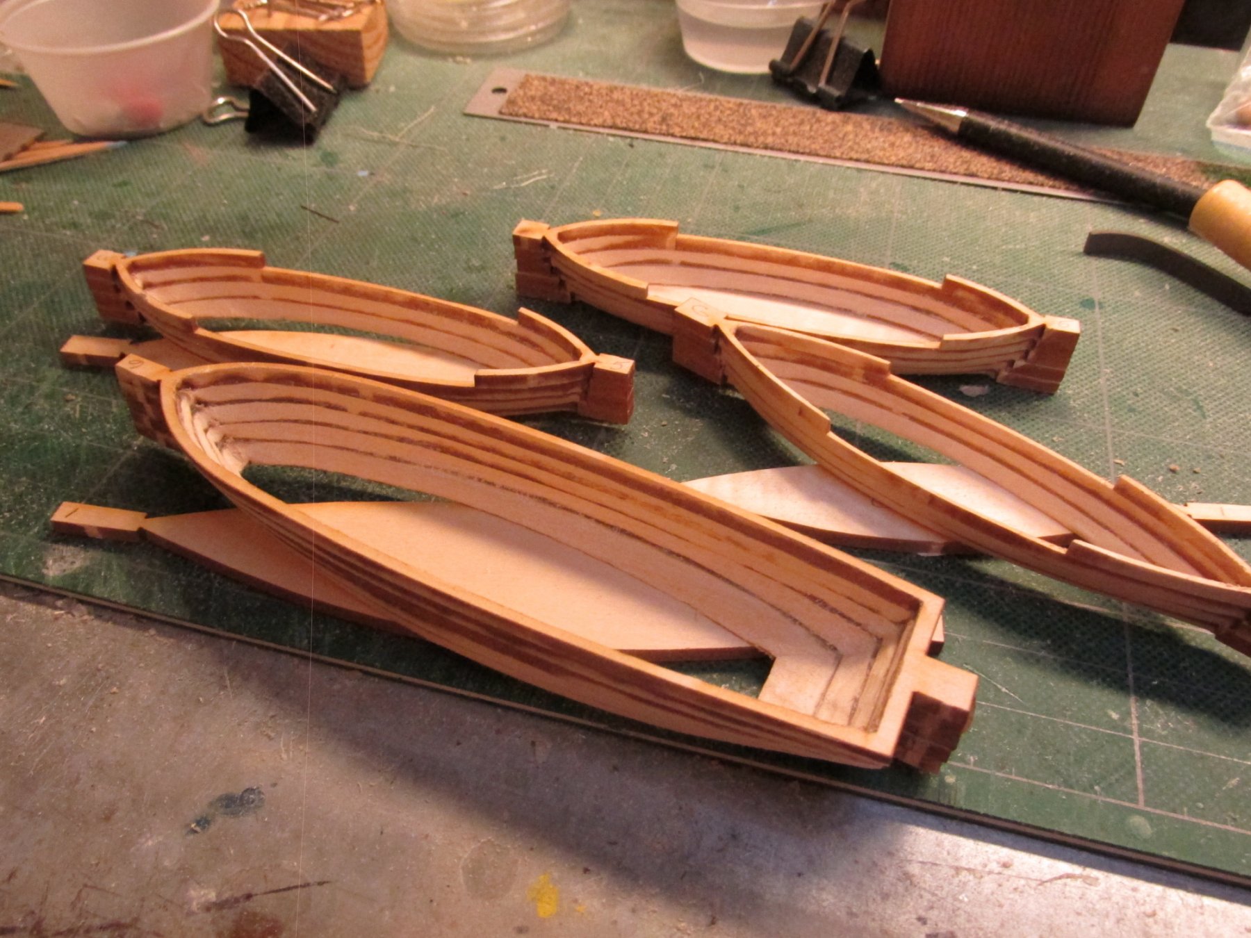
The bottoms were then glued on, the stems cut off, and the final shaping of the boats commenced. The final shaping was done using just files and sand paper. Following the lead of xKen, I used 3M Acryl-White Glazing Putty as a wood filler to smooth out the little inconsistencies He also suggested Bondo Glazing & Spot Putty – I just found the 3M version first. I just smeared it over the void waited about a ½ hour for light coats and a bit long for the thicker ones then filed or sanded off the excess.
-
Using a no-name Dremel like rotary tool with a drum sander for the wholesale removal of wood, various cutting bits for the more finer cuts, and finally hand files and sand paper for still finer detail shaping, I arrived at the basic shell shape of the boats.

- MEDDO, CaptainSteve, KenW and 3 others
-
6
-
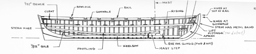
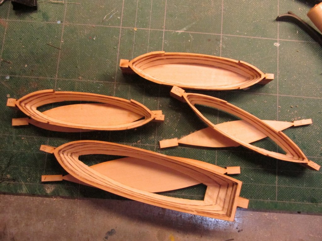
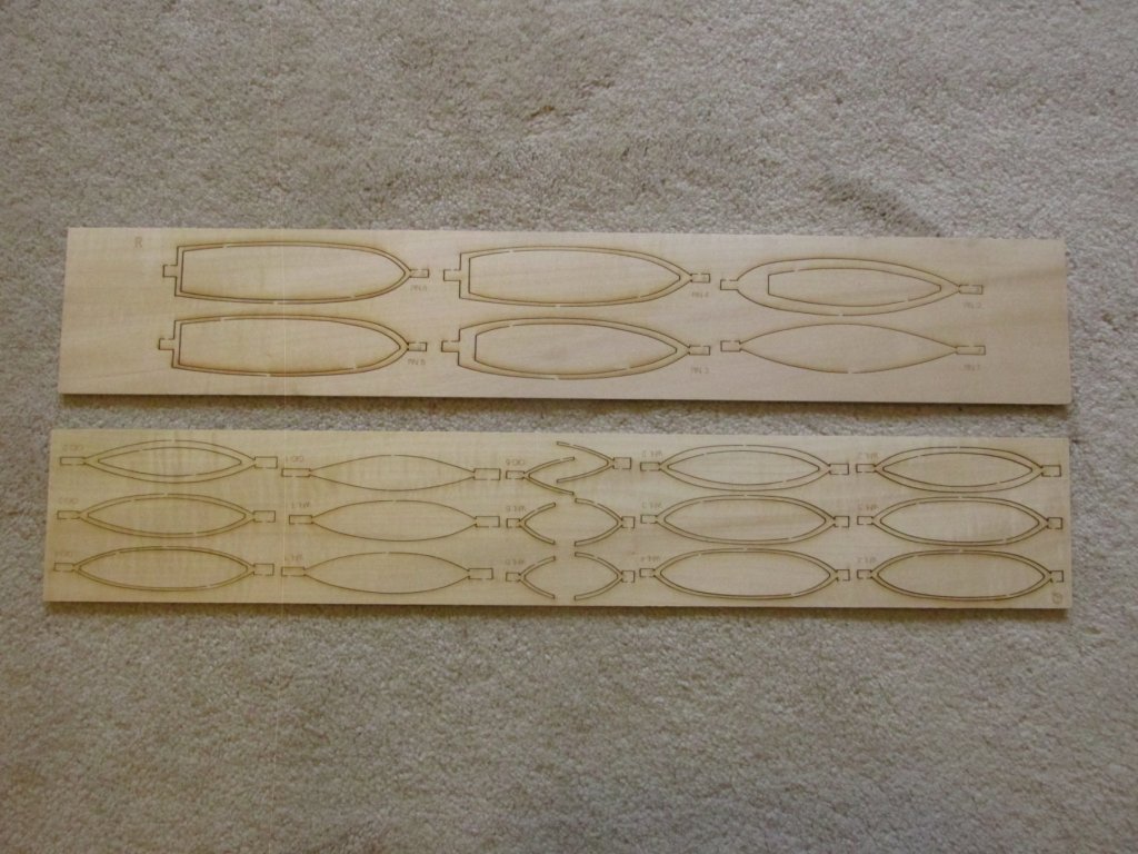
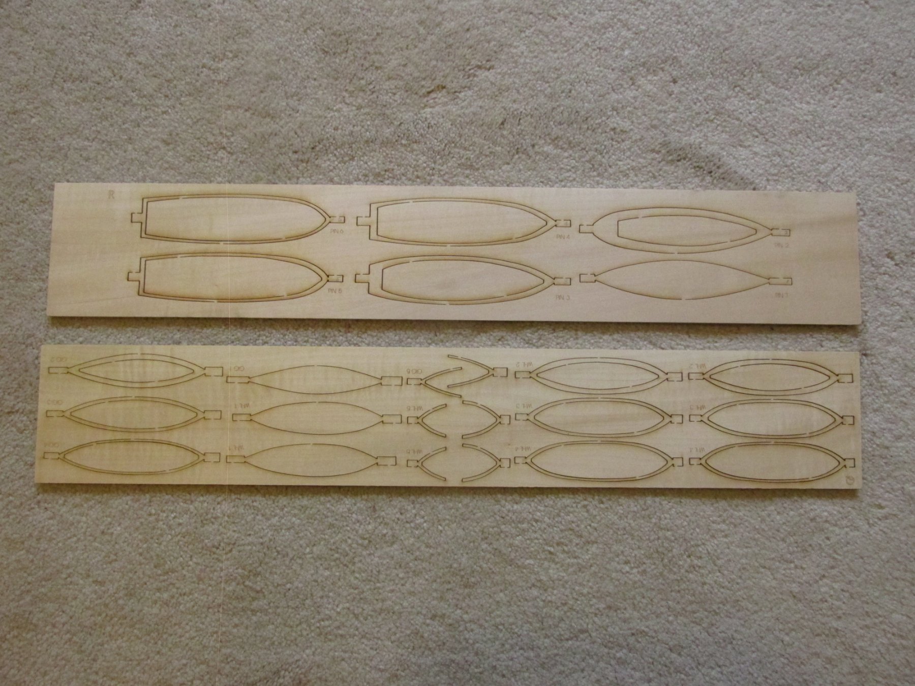
OK, it been almost two week since my original post and as I had mentioned before, I’ve deviated from the practicum by starting on the ship’s boats first. These boats are designed to be built as a layer cake, a method I have never done before. Using the tabs of each layer, the pieces are aligned for gluing. Having read numerous other logs, I knew not to glue the bottom layer so as to allow better access to the interior for carving, something the practicum did not do. Using my piece of nuclear grade stainless steel block of scrap metal I obtained many years ago, while working as a Quality Assurance Engineer at a nuclear power plant project (doesn’t everyone have one??), I simply weighted down the layer as they dried.

- KenW, Geoff Matson, CaptainSteve and 2 others
-
5
-
Thank you all! I did not realize I had created a "following" who looked forward to my next endeavor. I hope I won't disappoint.
Right off the bat I've deviated from the practicum and jumped into building the ship's boats first. I will post my comments and pictures soon; but if you've followed my Rattlesnake build, "soon" is a relative term. 8-)
-
-
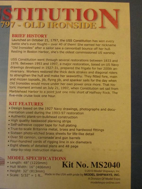
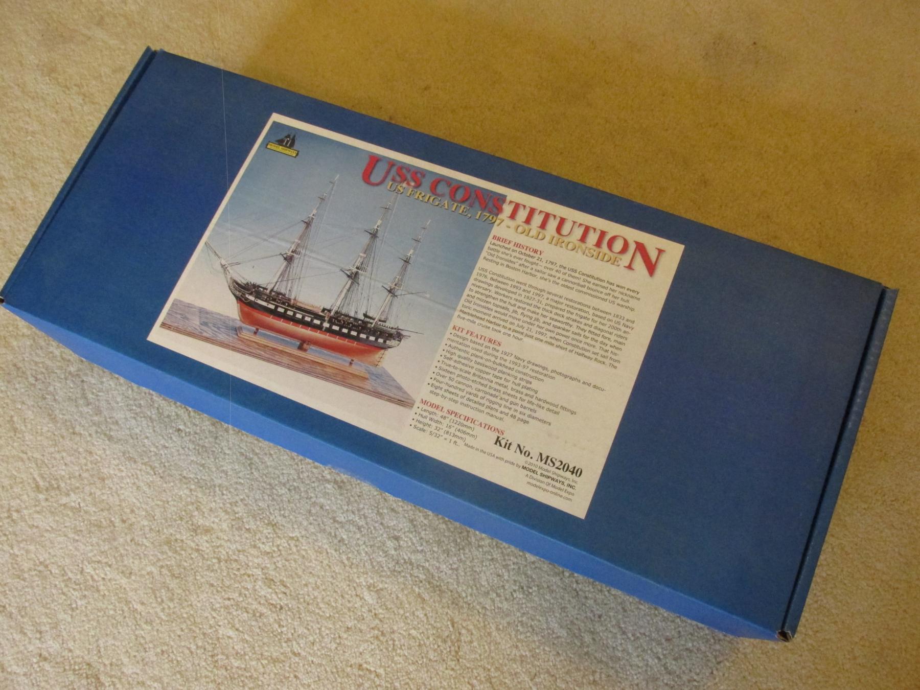
USS Constitution - Model Shipway’s Kit No.: MS2040
“Old Ironsides” 1797 Frigate
Scale: 5/32” = 1 ft. (1:76.8)
This is my second POB square rigged ship; I spent about seven years building my first, Mamoli’s Rattlesnake. Like the first one, I will be following Robert Hunt’s practicum, but unlike the first, I have a multitude of excellent build logs and books to supplement it and help guide me through the inevitable pitfalls that are sure to raise their ugly heads. Hopefully, based on this and my hard-earned experience with the Rattlesnake, it won’t take another half a lifetime to build.
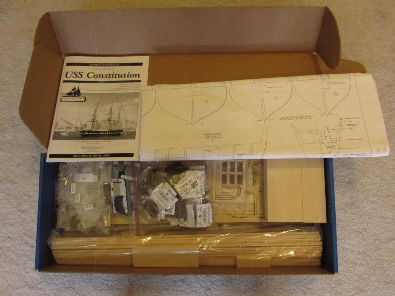
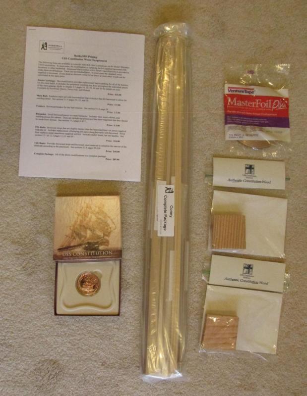
Now for the obligatory part. Below is the kit box and contents. I won’t bore you with showing all the little packets that are stuffed in the box, that has been done very well by numerous other builders. I will state that in addition to what came with the kit, I purchased a few more items:
· Robert Hunt’s practicum
· Hobby Mill’s wood supplement package (based on Hunt’s practicum) *
· Additional copper plate tape (as I understand it, the kit was a bit too frugal with their supply)
· 2 - 2½” x 2½” x ¾” genuine pieces of USS Constitution wood **
· Medallion made from genuine USS Constitution copper plate. Not sure yet how or if it will be used.
* Wood package purchased before HobbyMills closed shop. The supplement package was derived by HobbyMills where Mr. Hunt made his substitutions in the practicum. It was not identified as a package that could be purchased in the practicum. I have the original price list which describes what the wood is being substituted for and where in the practicum it is being described. If anyone wants a copy of the supplement wood list, please send me a PM.
** Constitution wood was purchased from the museum just before the ship went into drydock, December 2014. I have since tried to get a larger size for the keel or nameplate but accordioning to popeye2sea (who as I understand it volunteers on the ship), the US Navy is withholding any more wood from the public for now for reasons unknown. The museum told me, maybe in the Spring sometime.
This will be my third attempt at constructing this model. The first attempt was done when I was a child building Revell’s small plastic model which I really botched. I hadn’t yet learned to read and follow instructions, but just dove into assembling the parts with expected results. My second attempt was as a young teenager and when the wounds of that failed build had waned, went a bit better. This time I got the larger plastic model. I did follow instructions and even painted the parts but had absolutely no idea how a rigged ship worked let alone how the lines were attached or what they were for. It looked decent to my young ignorant eyes at the time. Both models met their demise at my hand with firecrackers; usual method of disposing such items
This time I expect a glorious finish…I hope.

- Duanelaker, Bill Morrison, Nirvana and 6 others
-
9
-
I'm overwhelmed! Thank-you all.
Jon
- Blue Pilot and Martin W
-
2
-
Gregory - I wasn't kidding about not having a woodworking background. When I started the Rattlesnake I owned some screwdrivers, a hammer, some wrenches, you know, your typical household repair stuff. I did not own a saw. When I started to buy tools, they were all for the model making. So I now have a Brynes saw, a Brynes thickness sander, a 35 yr old Dremel scroll saw, and rotary drills with a drill press accessory. Any wood working stuff I have is all for model making. I still don't own any full size wood working tools. 8-)
Jon
- CaptainSteve, russ, Jack12477 and 1 other
-
4
-
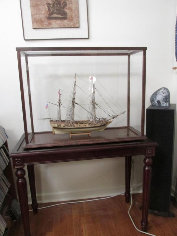
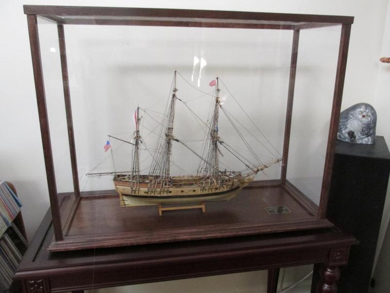
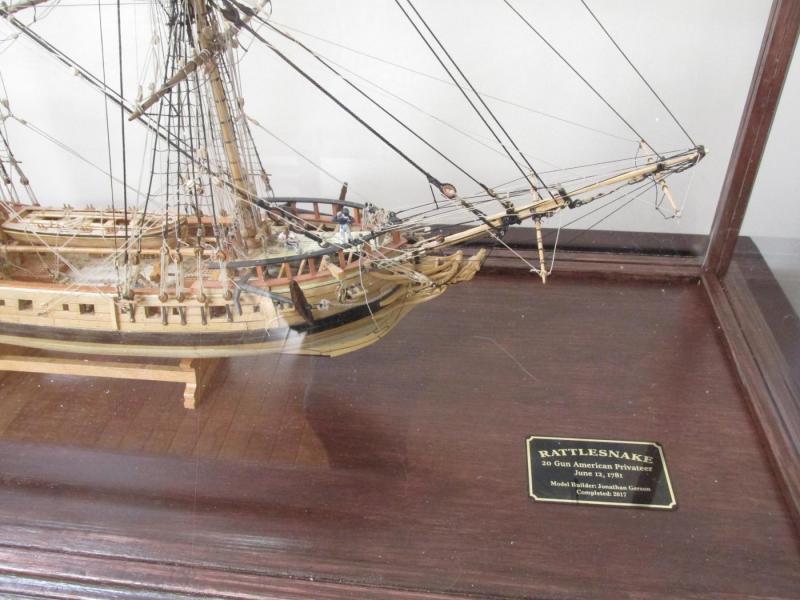
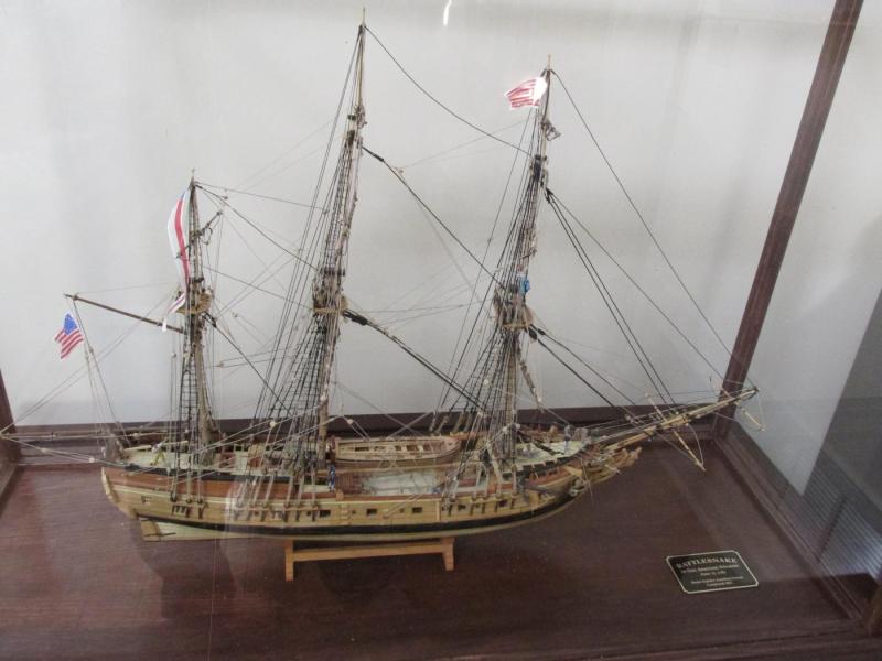
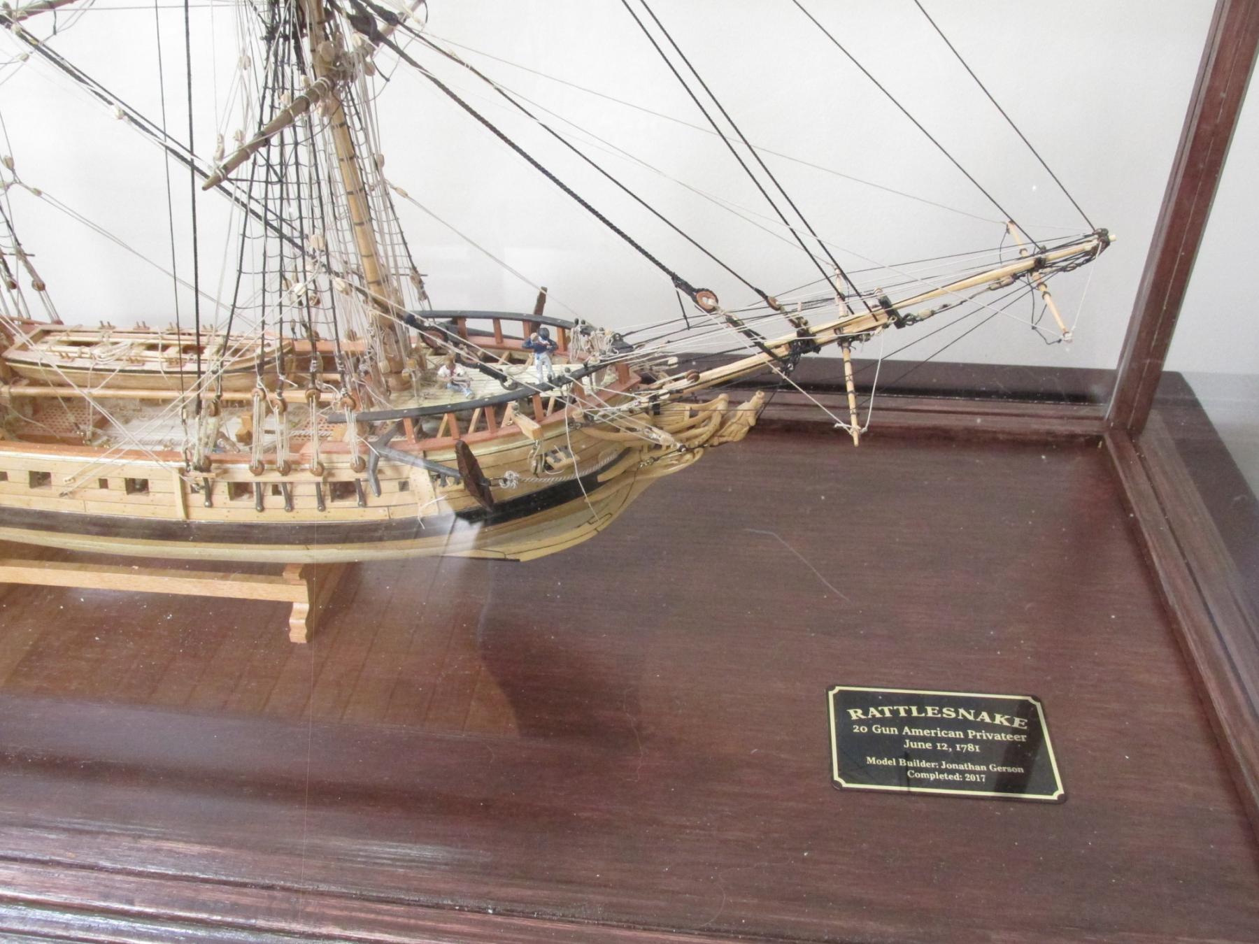
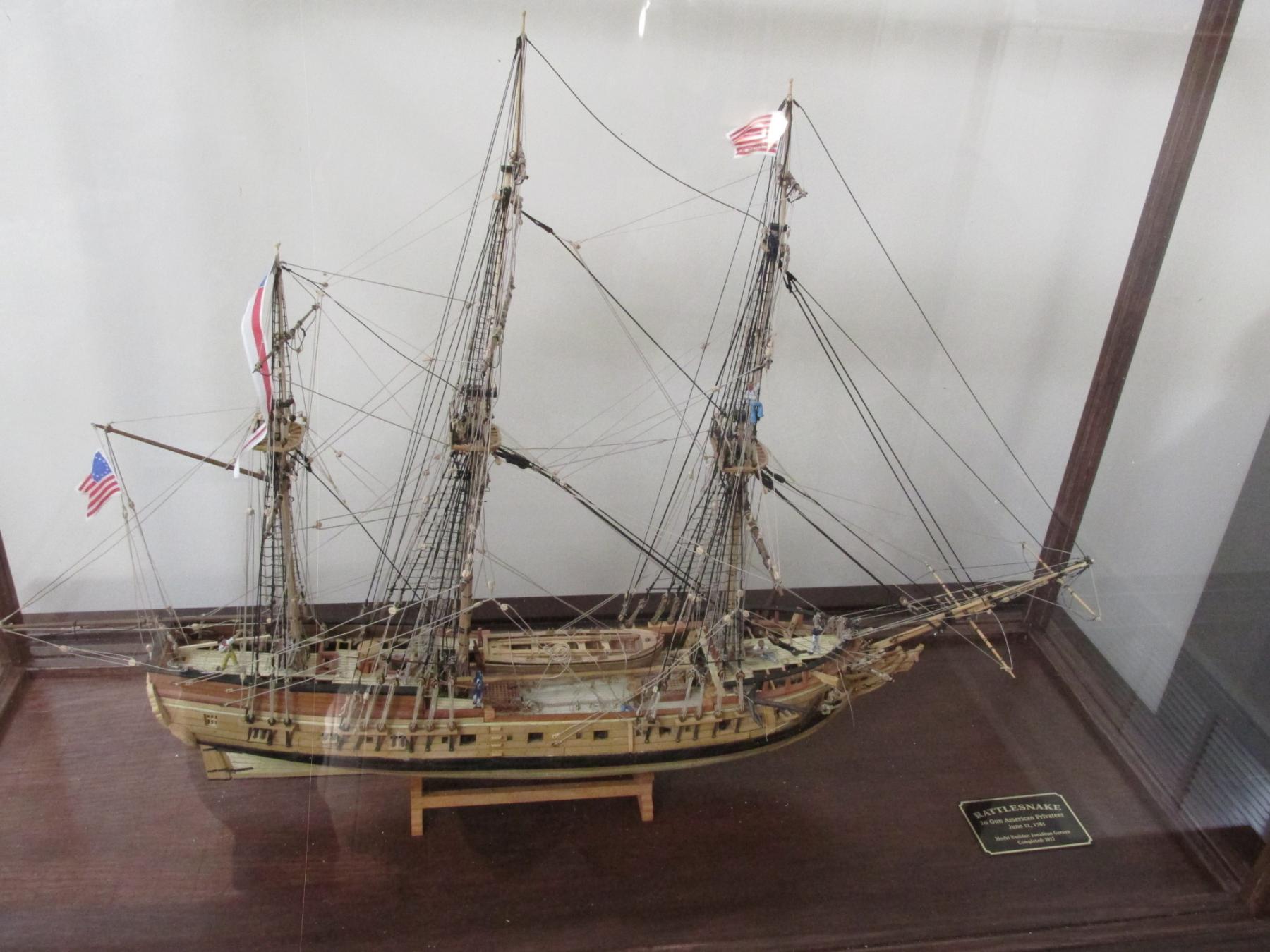
FINISHED
Well here they are, the last planned official images of my Rattlesnake, safe and snug in her case. For those who followed my loooonnnnnng and s l o w build over the past seven years, once again, thank you for being so patient and thank you for all the “likes.”
-
-
KenW - I got the 1/8" plexiglass at my local glass shop (auto and other repair). I initially tried Lowe's but they were all out. The I went up the street to Home Depot (they always seen to come in pairs, don't know why) and they did have it but they would not custom cut it like Lowe's would have. The third try was a charm; the glass shop had it and custom cut for me. They even re-cut it again (no charge) when I realized my dimensions were a little off and it needed a minor trim. I had to get 1/8" thickness because that is what the case required. Once the wooden frame was around the plastic, the panels were very sturdy.
The case (No. GM7W) I got from Model Expo as I mentioned in post #949 above
Hope this helps
To all - Thank very much for your "likes" and following me on this long slow journey. Once I've buttoned up the model in the display, configured and customized my new computer, and taken a small breather, stay tuned and I will start the next journey on the USS Constitution
Jon


USS Constitution by JSGerson - Model Shipways Kit No. MS2040
in - Kit build logs for subjects built from 1751 - 1800
Posted
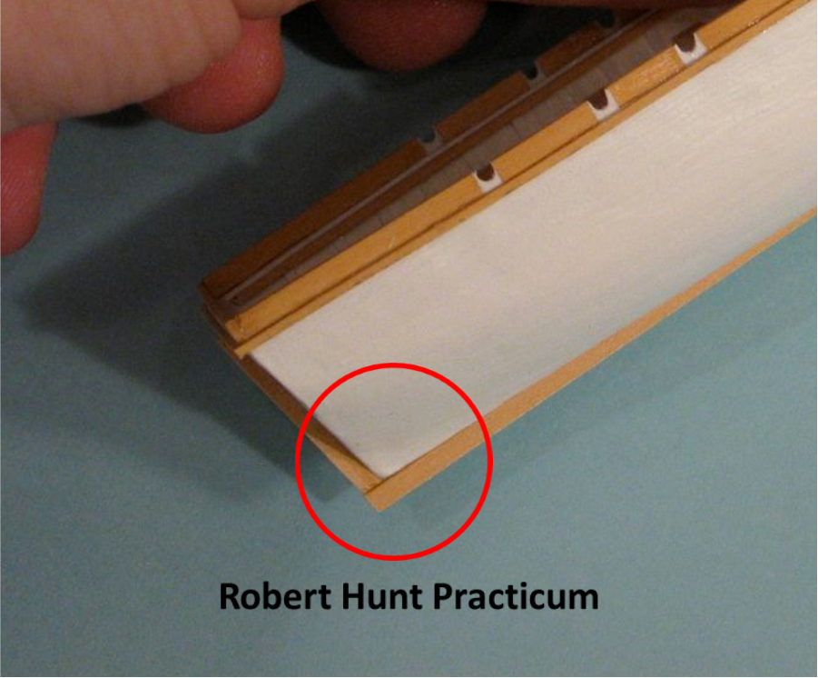
The practicum showed that Mr. Hunt had glued all the ribs in place and then glued the apron and knee on top of them. Both the MS plans and the US Navy plans show the apron and the knee glued directly to the shell with the ribs butting up them. This is what I did. Both plans show the keelson notched for the ribs and footings (which have yet to be installed) so it can be glued on top of the ribs and footings.