HOLIDAY DONATION DRIVE - SUPPORT MSW - DO YOUR PART TO KEEP THIS GREAT FORUM GOING! (Only 13 donations so far - C'mon guys!)
×


Piet
-
Posts
3,568 -
Joined
-
Last visited
Content Type
Profiles
Forums
Gallery
Events
Everything posted by Piet
-
 Very nice planking job Sjors. Looking forward seeing the copper going on her. Cheers
 -
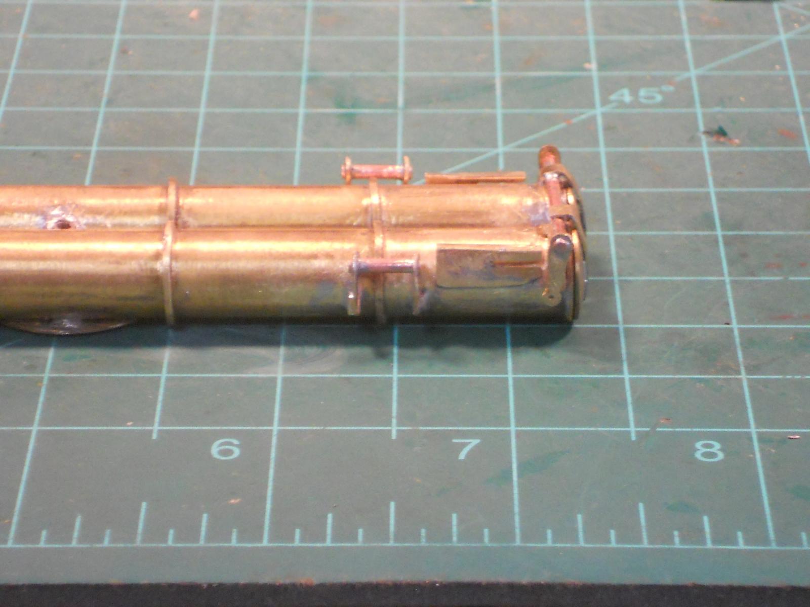
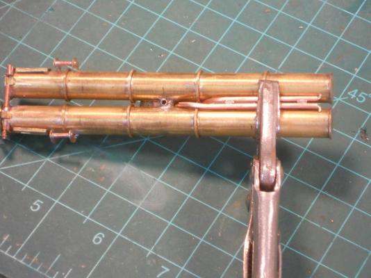
Hello everyone and thank you all for your approval of what I have done so far. Today was my third visit to the urologist center for my BCGI treatment. I figured not being able to accomplish anything because I have to be VERY close to the tinkeltarium. When the urge comes to pee I should be there already before I have an accident and Gwen would not appreciate that The garage, aka shipyard, is at the other end of the house - - - hmmm, what to do - - - - - Well, I figured the h--l with it and I'll use the great outdoors That's one of the advantages of being a male Okay, so I continued with the piping on top of the launcher, all running fore to aft or aft to front if that pleases you The cross pipes seem to fit over them. I hand-shaped each pipe to fit on their respective side and position and then tack soldered them to the launcher tubes. I could have used a third hand though but it all worked out okay with some Rube Goldberg rigging I only took one picture, y'all know how to bend brass rod to make it fit where you like to have them. All slow going, one bend at a time. Bend, try, adjust, try again till being happy. The cross pipes will be done some other day. Today was a challenge on the physical side but I did accomplish something anyhow. Here is the picture for your perusal. There is still a lot of cleaning up to do and some final pushing or pulling to get the pipes just right. It's starting to look a little like the photo now, which makes me happy. Cheers,
-
Hello Omega and welcome to my humble shipyard, glad to have you. No, my friend, to the contrary. I do like the accolades - that keeps me on my toes not to mess up on things Besides, my father was a very critical man when it came to the safety of the crew and this build is in his honor and all those who sailed on her. In a way I feel his eyes peeking over my shoulder, which keeps me from screwing up - - - most of the times All the accolades I receive is taken as an expression of your approval. I also welcome constructive criticism and questions because sometimes I don't see the trees for the forest. Oh, I used to have this problem with being a little conceited at times - - - a little, my wife used to say, ha! - - - well, that quickly knocked the wind out of my sails. No, this model will be static, not RC. As mentioned throughout this log the build has gotten a life of its own. It started out as a simple 1:100 scale model without any working parts. Well, it kinda grew to what we see today, which caused many challenges, to say the least. Come and visit again, the coffee is always brewing Cheers,
-
Superb workmanship Pete, just a great looking hull. Cheers,
-
Hey Mark, kudos to you for a daring operation. Now you know how I felt hand drilling holes in VERY expensive aircraft parts. Sometimes, with really complicated parts I used two assistants to eyeball the drill motor being square to te part. Can always blame it on them when miss-drilling Cheers,
-
Congratulations Nenad, the copper plating really looks great and will even look better when offset with the black paint above it. Cheers,
- 4,152 replies
-
- 1
-

-
- cutty sark
- tehnodidakta
- (and 1 more)
-
Hello Pete, no problem with building the airplane but it was time and money though. But a nuclear submarine??? Oh, I had some crazy plans of building a mini sub out of steel 55 gallon drums but that's another story. Then I was going to build a ferro cement sailboat in the backyard. Lots of plans, lots of ambition but it was always time and money that stood in the way. Oh well, it's nice to look back on but I'm not complaining, can't turn the clock back. Cheers,
-
Thanks everybody for dropping in and your comments - - - and all the likes !!! Hoi Remco, thank you, it's my pleasure and it's to entice others to try there hand at metalwork. It appears to have worked, looking at your musket! I would have like to see how you fashioned the striker assembly though Hmm - - now - - a steam locomotive?? Live steam? It's a funny thing you mentioned that, there was a time before I got married with Gwen that I was seriously thinking about it. But alas, I bought an airplane instead - - - which I had to sell when we had our first daughter, and starting a business. Seriously though there are brass loco kits available. That's also a serious hobby here in the states and when done right can fetch a good price. Hey Dave, good to see you again but a nuclear boat????? Hmmmmm - - - maybe not You are overestimating my abilities, there are limits to what I can do. But thank you - - - oh shoot, my halo just lit up Actually, making a model of a nuclear sub is no challenge. Awesome as they are, it's just a long black cigar with a conning tower on top, no deck furniture. What I really wanted to build was a four place single engine airplane! I still have the drawings. I was going to install a 180 HP four cylinder Lycoming engine in it with a controllable pitch prop. But - - - life got in the way and so - - the plans are all in a box. Perhaps in my next life Hi Pat, thanks for visiting and your compliments!! Spaghetti junction indeed. Did you see that photograph? I don't think I can put all them pipes and tubes on this launcher but we'll try to make it look like they all belong there. I'll just keep that photo hidden
-
Hoi Remco, SUPERB !!! Cheers,
-
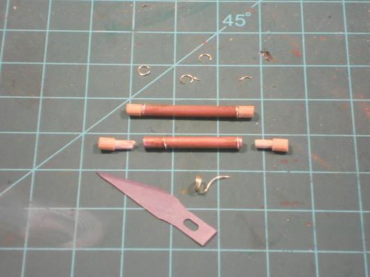
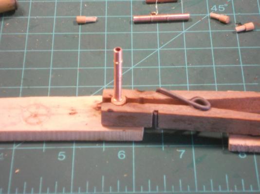
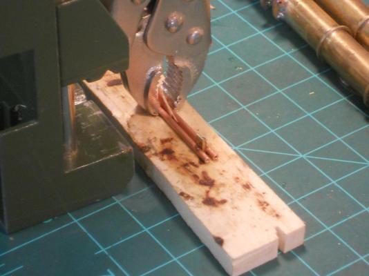
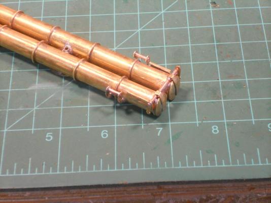
To everyone who visited - my heartfelt thanks and your likes. Well, after the center pipes were installed I moved to the aft outside of the torpedo launcher. I wanted to fabricate the two, what seemingly appear to be high pressure cylinders. Perhaps one of the sub guys with knowledge of WW II era subs can tell us. In any case, what they are is at this time not important. All I want to do is make this thing appear kinda similar as what the original photo shows. I'll have to do a lot guess work as far as the aft end is concerned. Okay, I cut two 12 mm lengths of 3.1 mm copper tubes for the cylinders. Then I needed to fabricate the domed ends. I could have made them from brass rod but decided to use hard-wood dowel, a little easier to work with and faster These pieces are just a smidgin larger in diameter then the copper tubes, which is great. Then I cut formed them into a mushroom style plug. The pictures below show you what I mean. I also needed to make flanges just behind each plug, I made them from 0.05 brass wire that I hardened by pulling it. Then I wound it around the 3.1 mm tube to make at least 4 rings. Now I had to solder these rings at each end of the tubes, aka cylinders. I made a larger version of a mushroom type plug so that these rings could but against them. This assured me that they are at the end of the tubes. Then I rigged up a clamp from a large cloth pin to hold the large plug. I shoved the bras rings against it and started to solder, easy, peasy. Just a little cleaning away of some solder. Next I epoxy cemented the wooden plugs to the tubes and let it cure before fashioning them into the domed cylinder ends. As the epoxy was curing I started to make the air or hydraulic lines. I used 0.9 mm brass rod for them, at least that's what looked about right for scale. By the time I made three of the lines it was time to make the domed ends. I first carefully sanded them to the correct lengths on my Large Craftsman sanding machine and then by using a file fashioned them into nice domed ends. They looked good to me and are now ready to be soldered to the launcher. Hmmm, that's going to be tricky because I have only one flange on the launcher tubes I can solder them to. I'll have think of a way for one more fastening point but that can wait till another day. I'll let you know that I also relocated the door actuator cylinders a little more aft. This'll give me a little more room for the articulating rods. I don't know how much time I'll have tomorrow. I really need to cut back a lot of vines and palmettos that are taking over in the vacant lot next to our house. The vines are spilling over the fence and are generally a nuisance. Well, that's it for today and here are a few pics for my own archive I'll share with yuns. Here I have laid out all the parts that make up the two cylinders as mentioned above. It's kinda self explanatory. This shows my soldering set-up. Yep, it's crude but itworks. Here you see the copper tube set on the wooden end piece that I clamped in a clothe pin. The brass ring is now pushed tight against the wooden plug ensuring it's at the end of the tube. Just a light touch of the soldering iron and presto it was done. All I had to do was clean off a little solder. This shows the finished cylinders. There may be one or two of the rings that are not quite correct where the ends meet but they will be facing towards the torpedo tubes and out of sight You see Ian, I mostly use hand tools Here you see a few of the small lines, either air or hydraulic. I don't know yet how many I'll be making. There are whole bunch that seem to run cross wise with little gizmos between them, could be check valves. It'll make for a busy top-side of the Launcher. Cheers,

-
Hello Pete, thanks again for your compliments. It's a labor of love as your cup boats are. Hi Sawdust Dave, wow, you make be blush Such kind words! Now, as far as master craftsman is concerned - - far from it. After my service with the Federal Aviation Administration and before that as VP of Maintenance and Director of QC for airlines after oh - about 26 or so years, I lost a lot of my former dexterity with tools and fabricating things. However, it's slowly coming back though It's amazing how the human mind and body are designed! Not to blow my own horn but yes, when I managed my own aircraft repair facility in New Jersey I was listed as a master welder and master aircraft and engine mechanic. I am extremely glad that everyone enjoys my work and hopefully pick up a few ideas and the urge to try your hands at metal work. That's one of the reasons for so much dialog but also so that I have a record for myself. Hello John, welcome again and thank you very much. Hi Ian, thank you too my friend. Ah yes, using power tools instead of hand tools. I only use power tools on these small parts when it does a better job. In this case I used a tapered rotary file, using the tip only, that worked better then my tiny rat-tail file. I also had better control over it because I worked over my lap with the left hand resting on one leg and the right hand with the tool resting on the right leg. After a while both legs start to cramp up though and then I take a water beak In previous posts I have shown and talked about how I filed the skin off my fingers because I use these fingers as a steady rest and guide for the file as I hold the part. Clamping the larger parts in a pin vice or small hand vice, as Remco told me to do, will help of course but many of my parts are just too small to do so, so I'm stuck using my fingers Cheers to all,
-
Great show Pete, thanks for the tutorial. Had I known before glassing my O19 hull with the stuff I am used to from my aircraft fixing era, I would certainly have used this stuff. Oh well, always good for the next build. Cheers,
-
Hoi Remco, that's some serious looking metal work, especially the flint striker assembly. Fantastic job. btw, how many are you gong to make for ship's compliment??? Cheers,
-
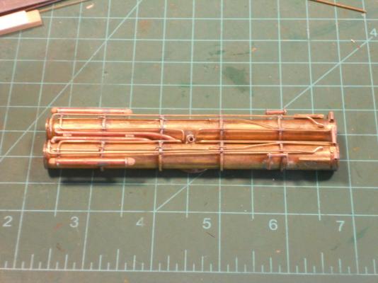
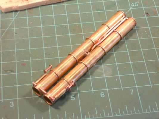
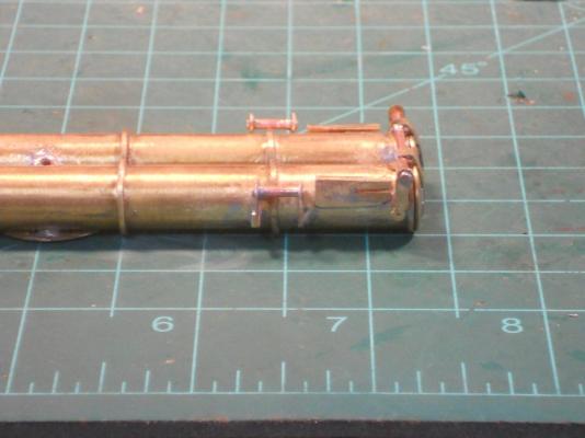
Thank you all for visiting and your likes, much appreciated. I'm glad that all yuns like my build!! After helping Gwen sawing off a few dead branches from our bottle brush bush and some other minor yard work I mozied on into the garage to work some more on the torpedo launcher. I decided to move to the aft end of the launcher unit and attempt to fabricate the center air tubes and hopefully solder them to the launcher. I'm still thinking about the door actuating system. I may have to move the actuator cylinder back a few mm's to give me some more space for the wiggy waggy rods I took a 1.6 mm copper tube and cut two pieces off that would fit as the photo shows. To make the bends down between the two tubes I inserted a small length of brass rod, to prevent the pipes from collapsing, and carefully started the bend from the end of the tubes and worked my way back till I had the right bend. Oh, I checked it several times though I must have bend hundreds of aluminum and steel pipes of various sizes for aircraft fuel and oil systems. There we used sand to fill the pipes and plug them with wooden dowels. Then we use commercial pipe bending tools. Well, these pipes are just too small to use that system. Sorry, no video but yuns know how to bend tubing, yes? I figured they needed to be slightly separated from each other and cut two small pieces of 0.6 mm brass strips for that purpose. To solder these pieces in between on the ends I placed first a sliver if thin wood, actually a piece of one ply from some leftover plywood. Then I could clamp the two tubes together where I put this piece of wood as a spacer and the clamp also acted as a heat-sink for the joint flanges. No problem so far and set this all up like a Rube Goldberg solder jig. It required very little heat and the solder flowed nice without much to clean off. The dry test looked good and fit okay. I next had to make the 90 degree angle at the aft ends for the air pipes to mate with the torpedo tubes. I filed the ends to about 45 degrees and cut two small copper tubes with one end also filed to 45 degrees. These small pieces of 1.6 mm tubes are also about 2 mm long and I figured I can file them to fit when checking again before soldering this assembly to the torpedo tubes. As one of the pictures show I took two small pieces of 0.6 mm brass rod and bend one end to about 45 degrees. I slid the longer end of the bend up rods into the pipes and then the small copper tube pieces on the short ends till they met the 90 degree cuts of the pipes. They mate up pretty good and figured that the solder would fill in the gaps and I could file a nice looking end bend in the pipes. This may be a crude way of making a 90 degree bend in a pipe but it could not be done any other way with such a tight bend. I jigged this up again and soldered the pipe ends to the pipes. It worked okay and after filing away the solder and dressing it I had good enough looking bend pipes. Dry fitting, filing, dry fitting, filing, etc till I was happy with the fit and looks. Okay, now came the time to solder these air pipes to the torpedo tubes. I used a small pair of vice grips to hold it all together and used it as a heat sink. First I soldered the front of the left pipe to the flange. I cranked up the heat on the soldering iron to about 425 degrees F. It worked great, used very little solder. Now to solder the aft parts of the pipes to the last flange. It worked great as well and I'm a happy camper. It's beginning to look more like the photo now Okay, here are a few pics of today's work. This shows my Rube Goldberg soldering jig for soldering the spacers. The pipes are shown upside down. This shows both spaces soldered between the pipes. Here I'm dry fitting the pipe assembly. The aft ends still need work. Here you see my trusty vice grip plier to hold things together and as a heat sink. Here I have not yet filed the 45 degree angles to the pipe ends but I have made and inserted the small rods for the bend ends. I did not make a picture of fabricating the small ends of the pipes, sorry. But here is the completed air pipe project and you can see the 90 degree ends. Cheers,
-
Thanks Popeye for your encouragement, always a pleasure hearing from you. Hello Ian B, well - - yes but in this case it and everything else on the model must be painted. I am replicating my father's boat as she appeared in 1939 when my father sailed on her to the Dutch colonies, and after, till the end of 1940. The boat was made from steel and thus had to have a protective coating of paint on everything and lots of grease. Actually the paint will enhance the looks of all the parts and make it more visible. Just wait and see Good evening Pete, yes, I told her you like the pics and she grinned. Glad you enjoyed them and me trying to explain how I do things. I encourage everyone not to shi away from doing metal work, if you can build models from card or styrene then you can use metal as well. It's just a harder material to work with and instead of glue we use solder. Thank you for the compliments, always appreciated. Hi David B, yep, blackening does make metal parts really look great, but as I mentioned to Ian it would be totally out of place on this model except for the pulleys. Airbrushing certainly works great on small models and parts. On this model I used high quality RustOleum rattle cans because of the size. If I had used the airbrush I'd have to refill the cup a gezillian times. I still have two high volume professional DeVilbis spray guns that can use 17 CFM of air and a small professional airbrush. Still left over from my aircraft repair business in New Jersey. Only the airbrush still sees some activity. Cheers,
-
Hoi Remco and great seeing you back in the shipyard. Nice looking planking job, looks very spiffy. Cheers,
- 1,214 replies
-
- 1
-
-
- sloop
- kingfisher
- (and 1 more)
-
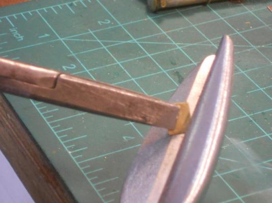
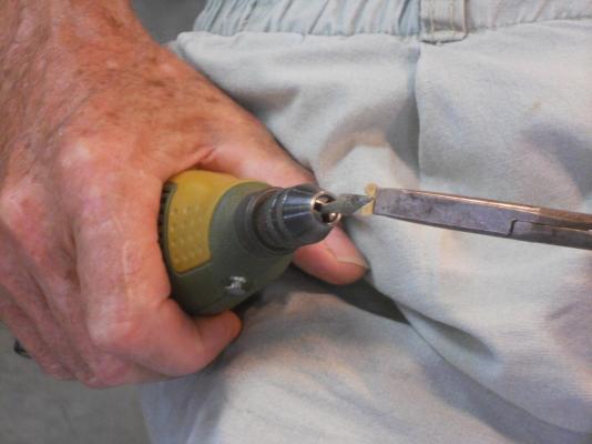
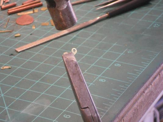
My wife Gwen saw me the other day with those big sheet metal sheers snipping away at those poor little parts and just shaking her head. Then yesterday evening she offered to take a few pics of me doing that to show all y'all that I was not kidding using those big sheers on these little parts. So this morning she snapped a few and I like to post them for you all. Today I continued with making a few more brackets and then attempting to solder them to the tubes. I again tinned the flanges and the spots on the tubes where the brackets are to be. I had to do it this way because I am only one guy and with only two hands. I placed a very small vice-grip plier in the already soldered parts on the launcher tubes as a heat sink because the forward bracket is close to shoe bracket. Holding the actuator bracket in my left hand with a small needle-nose plier I eye-balled the location and positioned the bracket to the tube and applied heat. I had to reposition the bracket several times before I was satisfied. Then I had to do the same thing with the aft bracket. That one too took several tries before it lined up horizontally even with the forward one. Cleaned up the solder around the brackets and then inserted the 1.6 mm copper tube into the holes and soldered them secure. I repeated the same procedure on the other side with the same shenanigans with having to reposition the brackets several times before they too lined up with each other and the one previously soldered on. Well, so far so good. Now I'm still thinking how to make the connection between the actuator and door handles. This has to be an articulated connection because the handle describes an arc. The photo shows it clearly but translating that to my model is a whole other thing. Oh, the difficulties we create for ourselves trying to make things work at this scale - - - - - - Okay, here are a few pics. This shows my large sheet metal sheers in action. I normally hold the piece between my fingers but they obscured the piece of metal for the picture so I held in a pair of duckbill pliers. It works really great, even snipping inside the curve. Here I am using my Poxxon hand tool with a tapered rotary file, works great but have to take the file away often to let the metal cool so as not to burn my fingers This shows my method of bending that 1 mm flange to the bracket. You can see the business end of my little hammer. This shows the launcher with the door actuator cylinder assemblies soldered to the launcher tubes. Another view. Cheers,
-
Hey Dave, with 20 mines on board I can block all yun's harbors and start shelling with my deck gun That way I'll miss the danger of your sonar equipped hulks and have free range to do some serious privateering - - bwaha ha ha ha laughs he with glee, wringing his hands in anticipation of plenty of booty. Hi Pete, yes, indeed they are awesome creatures. Early in the morning after breakfast I sit with a cup of java in the backyard and not too far from the flowers and feeder. The other day one of them flew very close past my head and even felt the displayed air as he or she went by with a buzzzzz zound. I was thrilled. And thank you for your comment. I just like to see people taking a stab at it and not shi away from doing metal work. Cheers to all,
-
Wow Pete, that's some serious boatbuilding! What a great display of those wonderful hulls, looking really very nice. I like your epoxy treatment. Cheers,
-
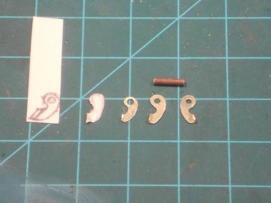
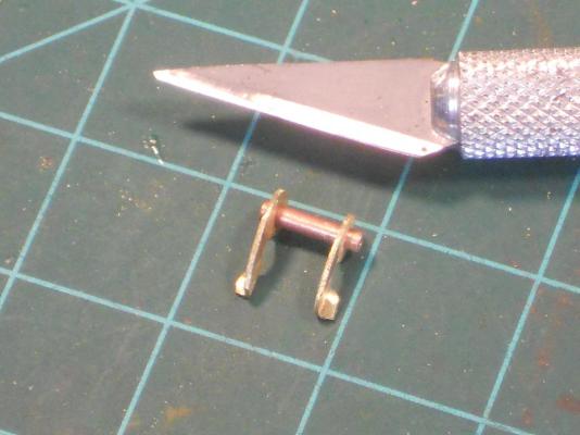
First of all I like to thank everyone for visiting and enjoying the build of my father's beloved boat by clicking the like button. Hope to see all y'all again soon. Today started out with doing some fish pond maintenance. Had to remove two pots with my leopard calla lilies to let the corms dry out a bit. Then mowed the front yard. I also mixed two cups of humming bird nectar for the pair of ruby throated hummers that come and visit our backyard. It's just a joy to see these tiny birds feed. We have a few nice flowering bushes they seem to like but not enough flowers to satisfy them. Okay, enough about our varied wildlife in the backyard and on with the O19. I managed to spend a few hours I the shipyard this afternoon and started fabricating the torpedo door actuators. Each one consists of three parts, at least that's what I'm doing. There's more to it then that. I have to close off each end but make a small hole in the front end for the actuator rod. Hmmm, another can of worms Obviously the first thing we need to do is studying the parts by looking at the drawing while holding the launcher next to it. I have done this now for the last few days to create a good mental image of how I am going to make this assembly. So, today was the day to make a start of it. I first made a sketch on some card stock of how I saw it in my mind and where the cylinder brackets have to have a flange where it'll be soldered to the round torpedo tube and at what angle. I used a small piece of the same size of tube to check the form and fit. After I had what I thought should work I cut it out and with a pair of tweezers held to to the launcher tube. In this case I saw that I needed to change the flange of the flange a little more to fit better to the round torpedo tube. Next I transferred this shape to a small piece of 0.1 mm shim stock to cut the prototype out for a fit. It's a lot easier to cut thin shim stock then the 0.3 mm I'll eventually use. A little shaping and filing then I bend the flange and held it up to the tube for a fit. Hmmm, not too bad but it still needed a little more angel at the flange to meet the curve of the tube better. I now transferred this shape to a small piece of 0.3 mm brass sheet and cut it out with a pair of rather large sheet metal sheers. Yeah, don't laugh but it's actually rather comical using such large tools on a piece that's smaller then your fingernail. But hey, it works for me. I bend the flange to it by holding it in my specially ground duckbill pliers and with a small hammer tapped the flange over. The width of these flanges are about 2 mm. I finished the bracket with a tiny rotary file in my Proxxon motor tool and small hand files. Then made the hole for the copper tube that'll act as the actuator cylinder. Checking it against the tube it seemed doable. I now had to make three more with two of them with the flanges bend in the opposite direction. I want these flanges to be on the outside for ease of soldering. I only completed two brackets for one side but started with the next two when it was time to quit. Eyes were getting tired and I needed to do some correspondence. The reason I am going into a little more detail is so that anyone who is a little afraid making small metal parts is to show that it's really no magic but just careful eye / hand coordination and shaping the part as your mind sees it. As you can see I don't have fancy miniature tools but only what I have from my days as an aircraft fixer. So give it a try, all you can do is waste some brass stock and time. It's a fun challenge. Okay, I made a few pics of what I have done this afternoon, doesn't seem like much but it all takes time, including the sketching and head scratching, This picture shows te steps involved. The first one on the left is the sketch. #2 is the rough cutout in card stock with the flange bend up on the left bottom. Not quite happy but remembered where to make adjustments. #3 Transferred to 0.1 mm shim stock and fashioned it to what I felt should fit. Drilled the hole by starting with a 0.2 mm drill bit and then successively larger drill bits. Not quite happy with the angle of the flange but remembered where to make the adjustment and transferred to to - - #4 a small piece of 0.3 mm brass stock. Now I couldn't use my sewing sheers but my large straight cut sheet metal sheers to just cut the major pieces away. The rest I did with a small diamond rotary file in the Proxxon tool and finished with small files. Next I drilled the hole for the copper tube using the same method as described for the thin part. This should fit okay. # 5 is the aft bracket in this assembly/. The copper tube above the two brackets will function as the actuator cylinder. You can compare this with the photo on a previous post. I'll have to remove a little more metal from the brackets, they appear still a little too large. This shows the parts loosely assembled. I'll have to solder the brackets first to the torpedo tubes and then the copper tube last. It'll take a little more heat to solder the brackets to the launcher tubes then is required for that small copper tube, otherwise I may have a real problem on my hands. Cheers.
-
Thank you Pete, you are most kind. But when I look at your magnificent Cub boats I can say the same to you my friend. Your love and knowledge for these boats shine in them. Cheers,
-
Hot diggedy chetah Nenad, or should I call you Tarzal Nenad . Your plating is looking really nice. Cheers,
- 4,152 replies
-
- 1
-
-
- cutty sark
- tehnodidakta
- (and 1 more)
-
Beautiful, just beautiful Pete. What else can I say. Cheers,
-
Hi Kevin, the windows came out just great, congrats! And the ship looks awesome, holding it in front you gives an idea of how big she is. Cheers,
- 1,319 replies
-
- 1
-
-
- caldercraft
- Victory
- (and 1 more)