HOLIDAY DONATION DRIVE - SUPPORT MSW - DO YOUR PART TO KEEP THIS GREAT FORUM GOING! (Only 72 donations so far out of 49,000 members - Can we at least get 100? C'mon guys!)
×


Louie da fly
-
Posts
7,989 -
Joined
-
Last visited
Content Type
Profiles
Forums
Gallery
Events
Everything posted by Louie da fly
-
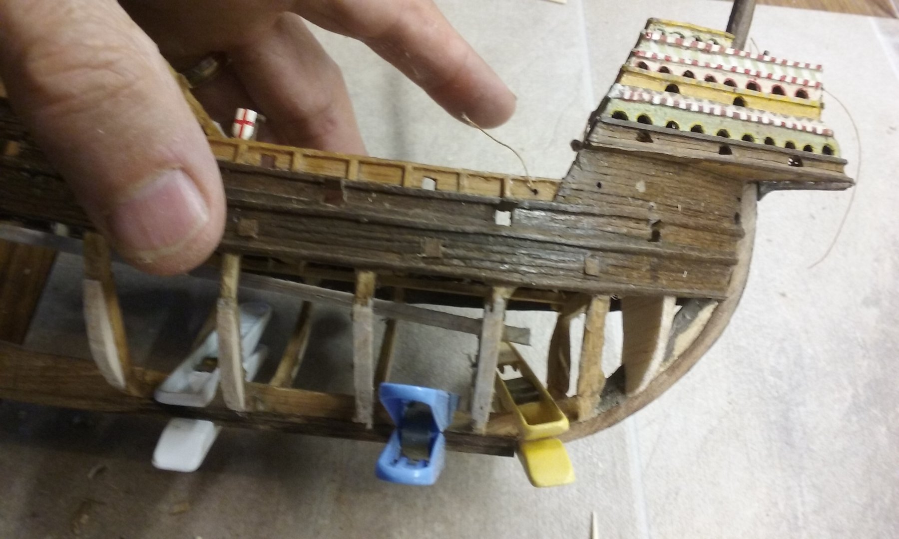
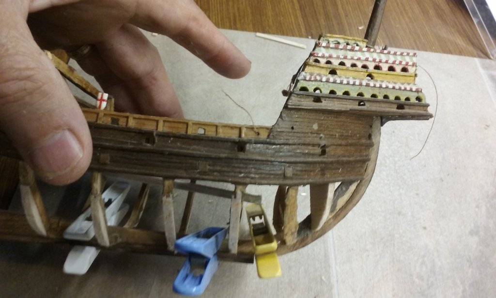
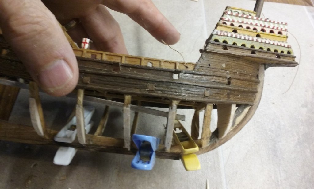
 I agree, Dick. However, it will be a while before I'm confronted by this problem and I've decided not to worry too much about it till then (the problems I have to resolve at the moment are quite enough for the time being). I'll be re-using as much of the original upper-work planking as I can, but there'll be a certain amount of new stuff I'll have to add, and the whole of the hull below the water line needs new planking. What I have now is walnut, rather than the "Queensland walnut" I used when I first built her. I think I'll be trying to match the timbers as closely as possible; the overall goal is to repair her to be as she would have been at the time, rather than to show up the repairs. The main deck is bamboo, made from old blinds. I may be able to get something similar. If not, I have a piece of bamboo I'll probably cut into planks for the upper deck. I've added the extra frames I needed. I had to reverse engineer frames, to be the right size to fit inside the existing planking (instead of making the frames first and then putting the planking on afterwards). The second-last frame is a bit skewiff so I'll have to undo and re-glue it, properly square. I've marked where the tops of the upper deck-beams will be on each of the new frames, and now I have to decide exactly what to do next. I'll be putting beams in, of course, but I may cut the frames off above the beams and add false frames where they're visible, in some wood more appropriate than balsa. Steven
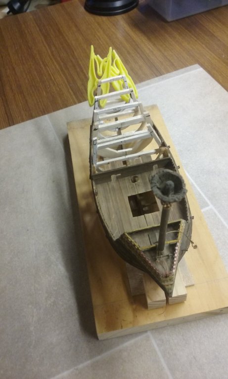
- 740 replies
-
- 5
-

-
- Tudor
- restoration
- (and 4 more)
-
Greetings from Wollongong Australia
Louie da fly replied to olopa67's topic in New member Introductions
Welcome to MSW, Paolo, from far-flung Ballarat. You'll find everybody here very helpful. Are you going to start a build log? Steven -
I think the idea that "My work is not good enough" is common to 90% of the people who start build logs, and often a disincentive to start one. But do it anyway. Nobody's going to criticize and you'll get a lot of support in your build. And (from my own experience) the "faults" that loom so large to you often turn out to be part of the learning experience. We've all been there, even the legends of MSW (which I hasten to add, don't include me). Fear of making mistakes often stops us doing anything at all, so jump in regardless - make mistakes and learn from them. And next time you don't make that mistake again. And every time you make a new model, it'll be better than the last one. Steven
-
Hi Kevin, Welcome to MSW. I agree, the members of this forum are unusual in their helpfulness and generosity. It makes it a lot better just knowing there's someone out there who can probably help with information or problem-solving if you happen to get stuck or need to find something out. It would be good to see some photos of your models in progress. Are you planning to start a build log? Steven
-
A nice piece of work. The ships of this period - the great days of exploration - are really interesting, and you're making very good progress with a very good-looking model. And I agree, a scratch build is a very special thing. I like the fact that you are cutting and seasoning your own timber for the ship. Walnut and pear are beautiful woods, and pear is also great for carving. You're lucky to have these timbers growing native in your country. In Australia where I live most people have to pay a lot of money to get even small pieces of European timbers. However, my home town of Ballarat is unusual; the street trees are mostly European - ash, oak, elm. Two of my neighbours have pear trees, and one had a walnut tree that died, so I got the timber. The translator seems to be working well. Though it uses unusual words for some technical terms (such as "plating" where we would say "planking") it's quite easy to make out your meaning. Best wishes with your project. I'm enjoying following it. Steven
- 197 replies
-
- 2
-
-
- santa maria
- carrack
- (and 1 more)
-
Thanks everybody for all the likes. Cog, unfortunately the wood is as tough as old boots, so I can't just shove a pin into it, much as I'd like to. And the smallest drill bit I can get is considerably larger diameter than a pin, so it would slop around in the hole. Druxey, Pat and Patrick, thanks for the comments. And Christos, Ευχαριστώ πολύ φίλε μου. Best wishes to all for the New Year, Steven
-
Beautiful weathering work, Greg. She really looks like she's been at sea for a good while. Looking at your post #173 I couldn't figure out why a WWI battleship would have a WWII funnel. Then looking further on I realised it was the funnel of the model behind her . . . Yamato? Steven
-
Another piece of "learning by doing" - probably the only possible way to construct the bow framing; hard to predict in theory, but the obvious road to travel when doing it in practice. Steven
- 263 replies
-
- 2
-
-
- nave tonda
- round ship
- (and 2 more)
-
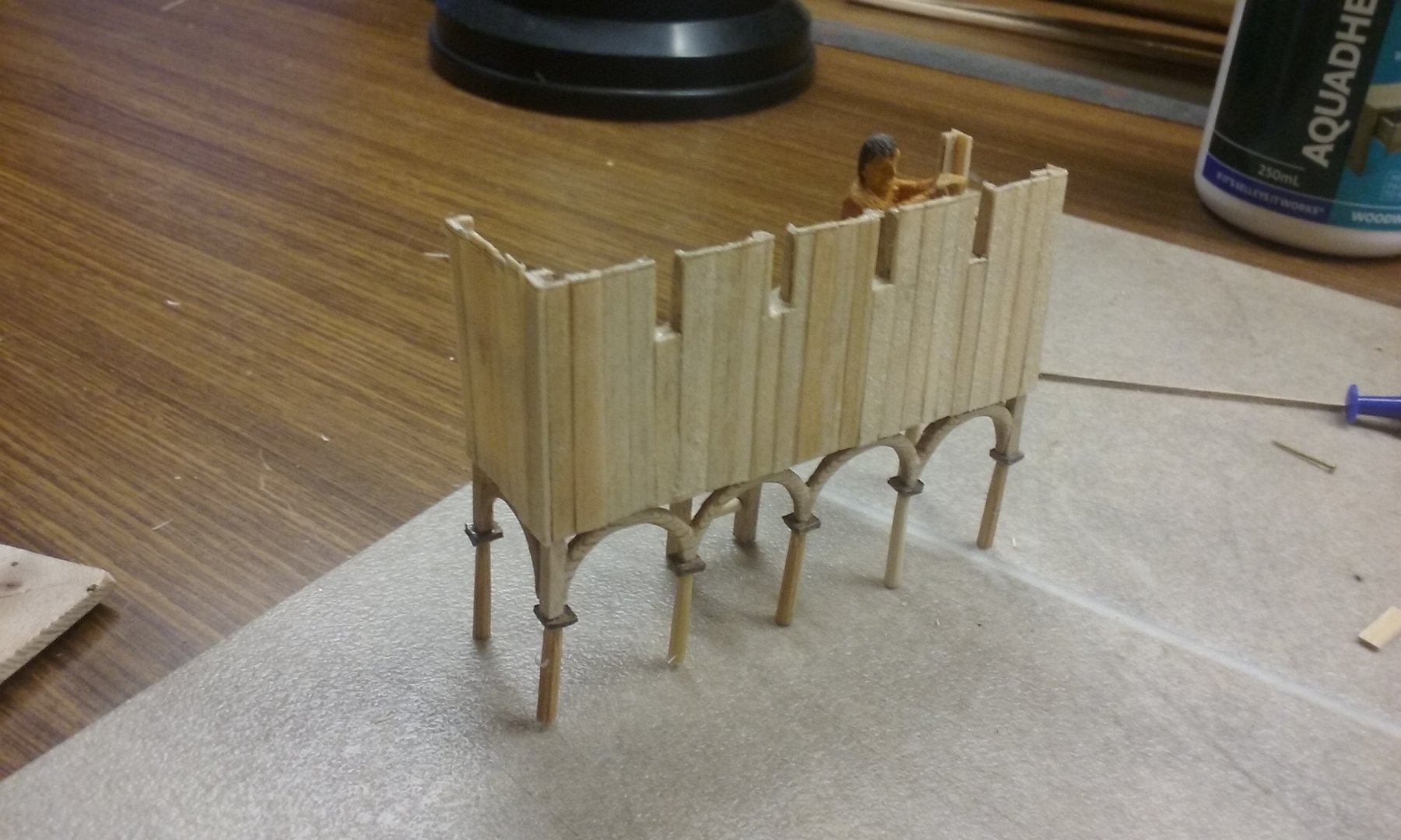
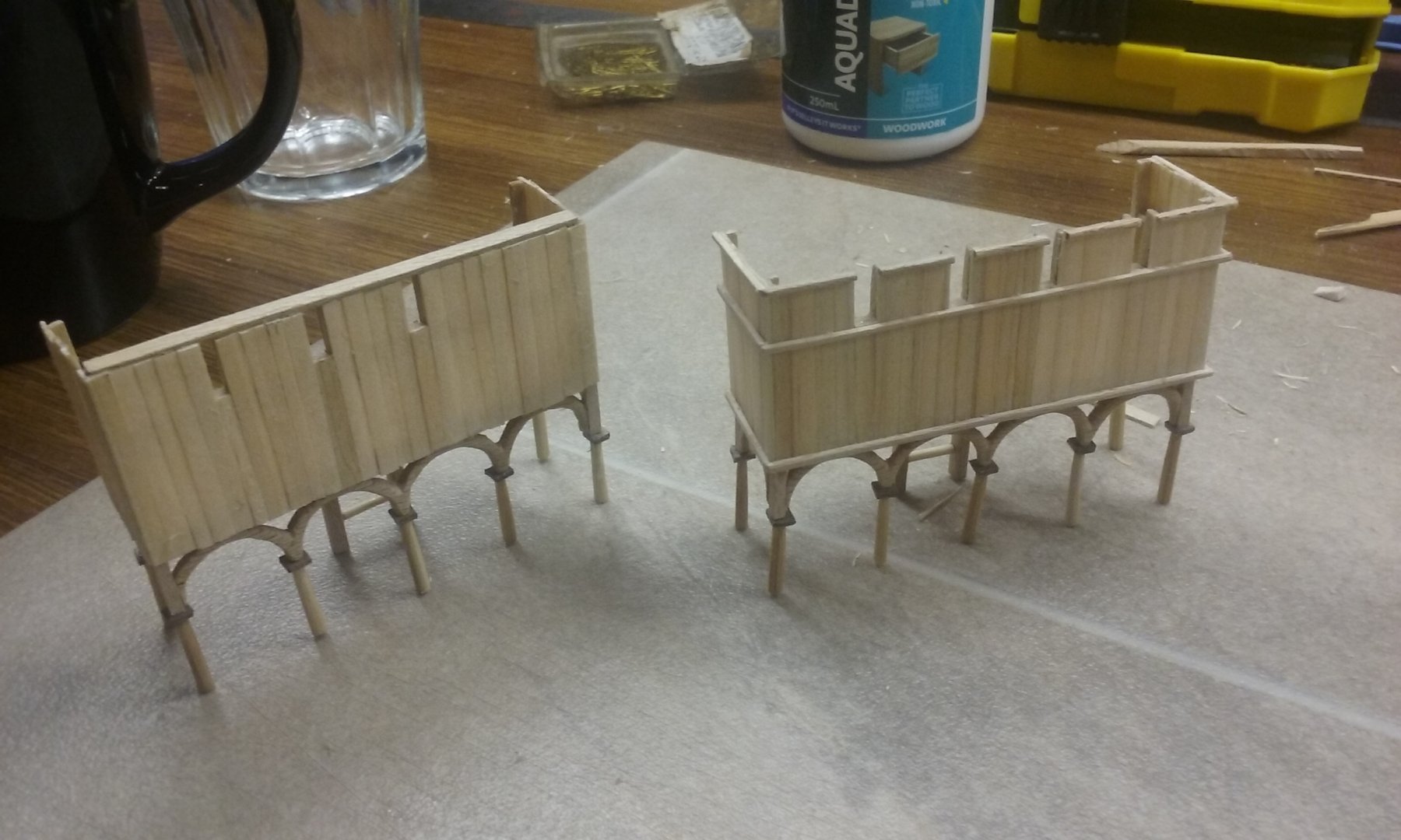
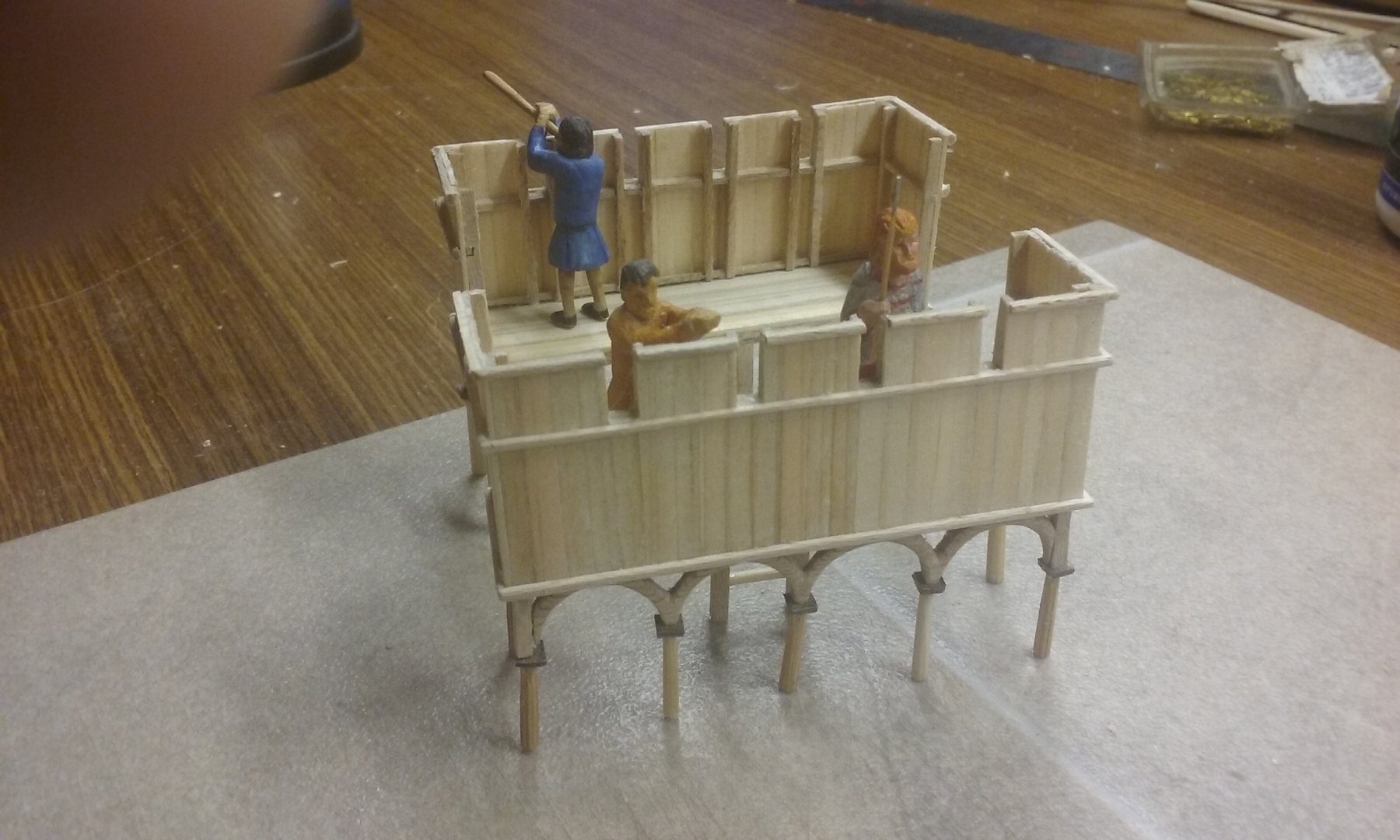
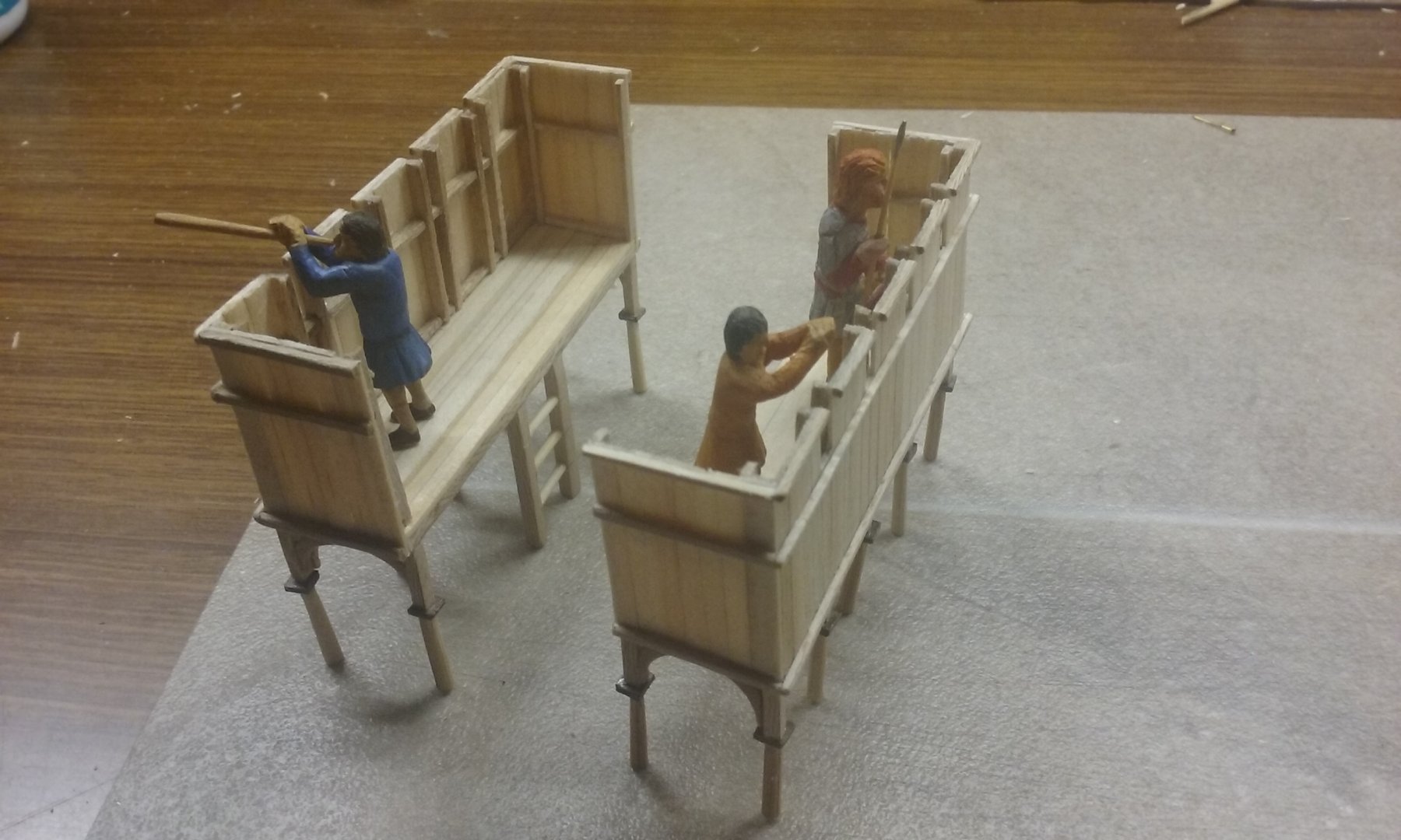
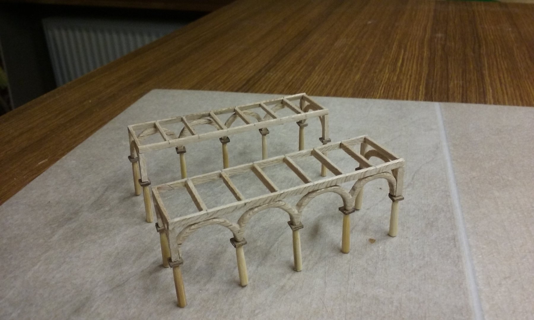
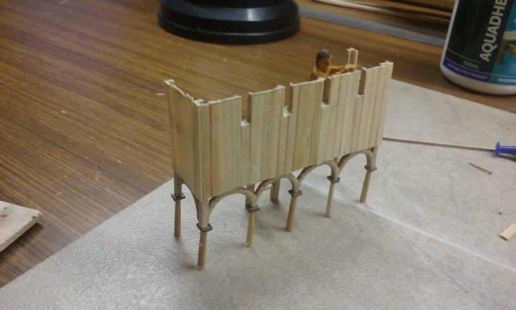
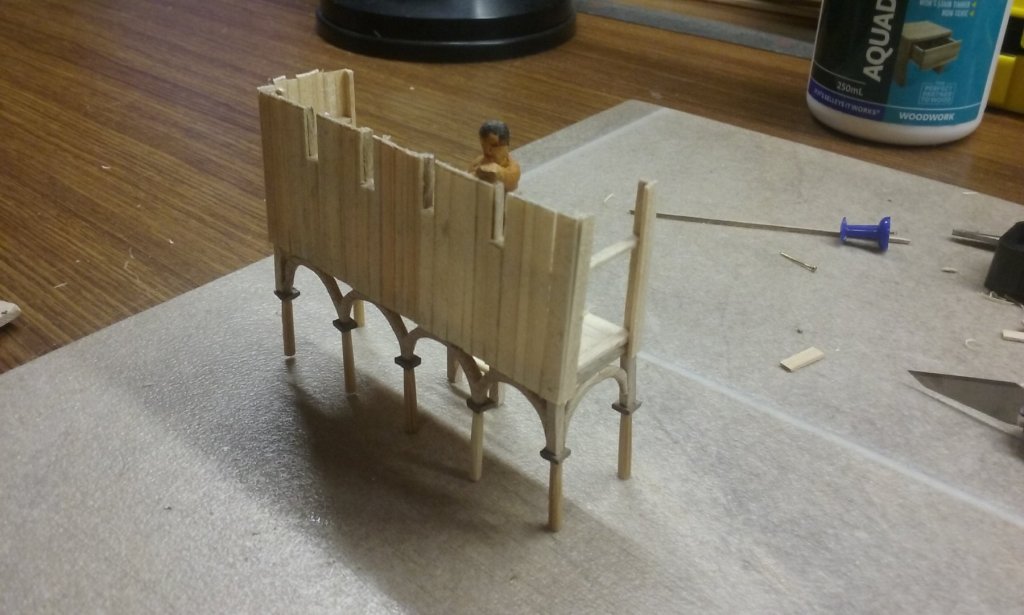
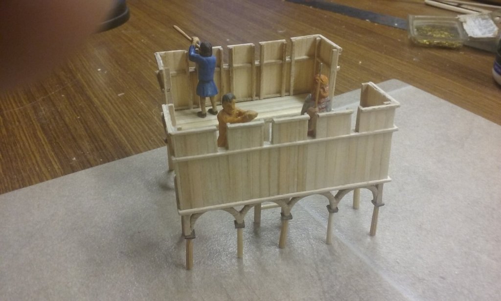
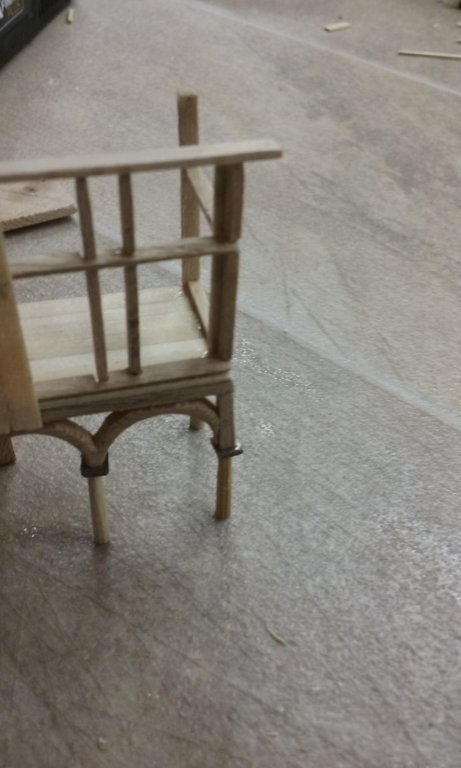
Thanks for all the likes, and thanks Druxey and Pat for the encouraging comments. Very much appreciated, particularly with what turned out to be a very frustrating stage of the build. Well, I've finished the xylokastra at last. Parapet planking nearly complete on the first one - with a crewman for comparison. Planking complete. I sanded it all smooth, but it looked a little bare, so I added some horizontals nominally to strengthen the structure but really to make it look better. Another column came loose, so I "pinned" it. I ended up doing this to all the corner columns, and even then I had to repeat the procedure with at least one of them because the pin broke. Next time I do this (for the forecastle or pseudopation) I'll do the columns last, because a lot of repair had to be done to damage which occurred while I was working on the superstructure. And I'll carve an integral pin into the end of each column to hold everything together, rather than (a) butt-jointing the tops of the columns and/or (b) drilling holes in the tops of the columns to add the pins. The same problem came up with the corner pieces of the substructure, and in future I'll pin these as well. As you can see below the corner piece came away along with everything attached to it as I was working on the superstructure, and the whole thing had to be repaired. The first xylokastron complete. The second one under way. And a comparison with the finished one. Both xylokastra complete and inhabited, with a crewman, a Varangian guardsman and a flute-player (for giving the rowing pace to the oarsmen). These aren't the guys who will be there - they're to go elsewhere on the ship. In fact I might leave the xylokastra completely uninhabited, as the vessel's not in combat. It's been a long and difficult process, but I've learnt a lot while doing it, which will stand me in good stead later in this and future builds. Steven


-
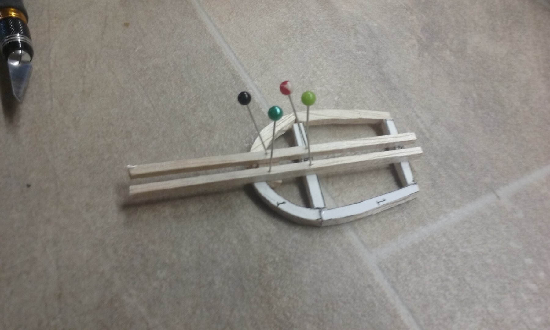
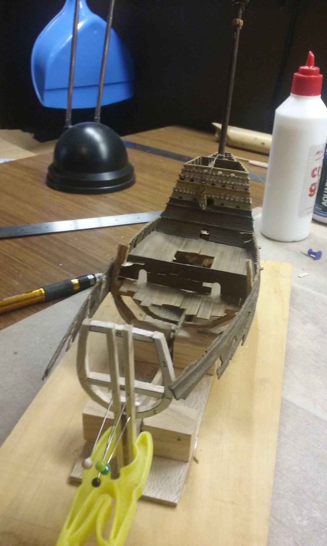
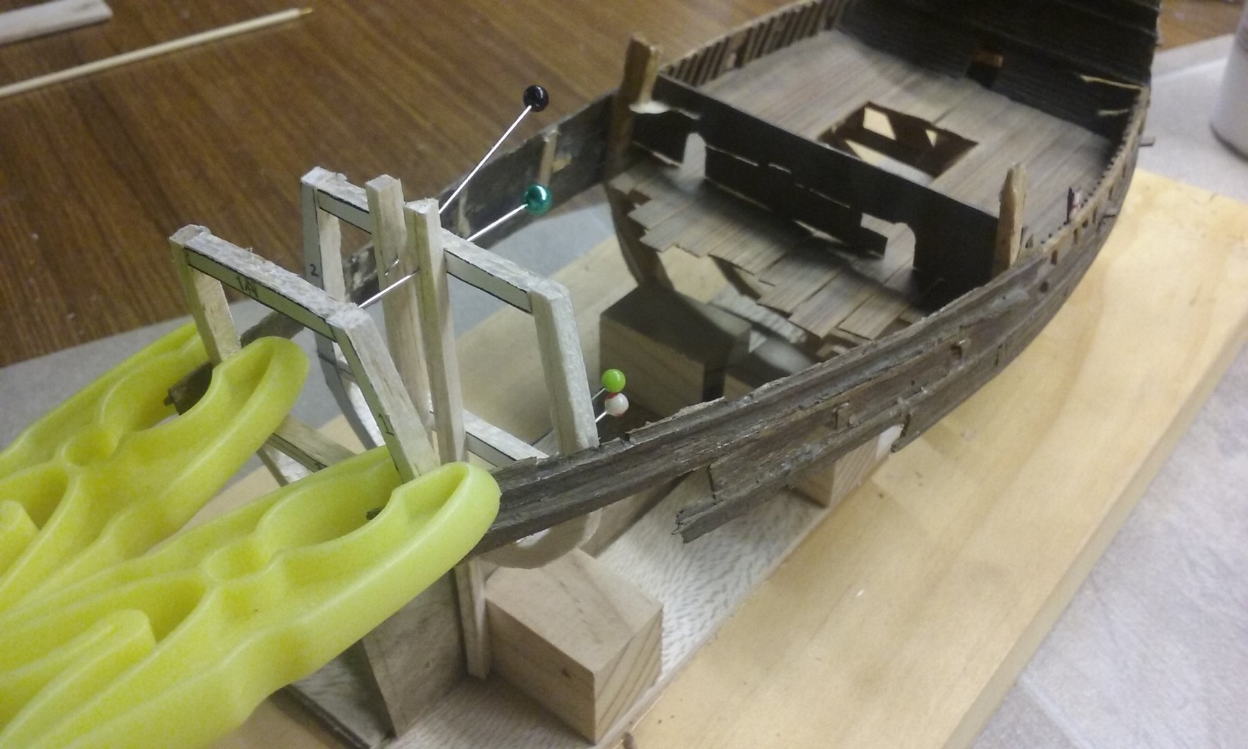
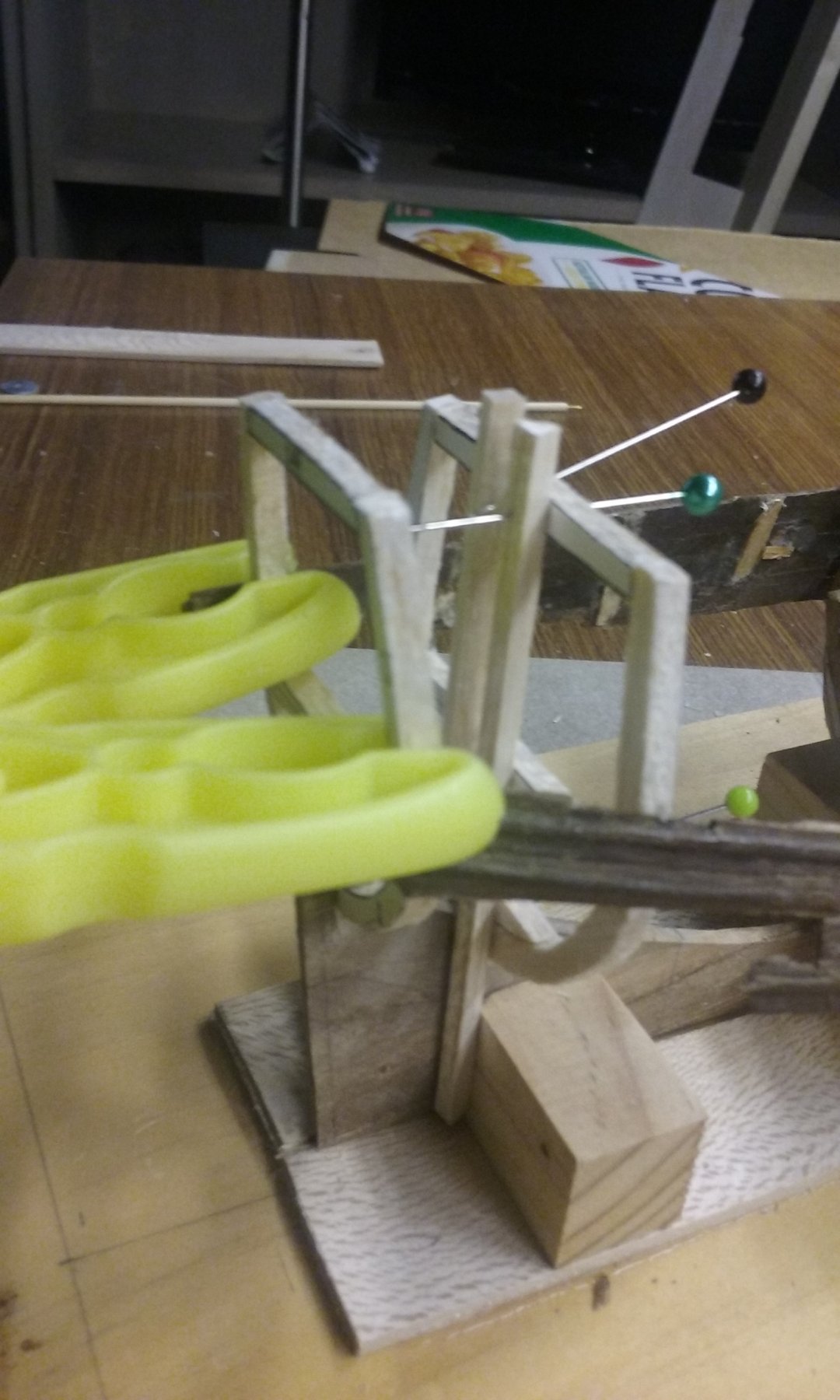
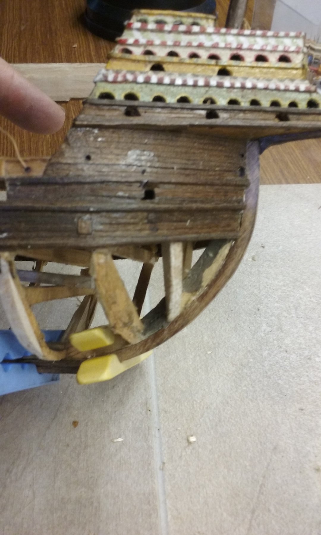
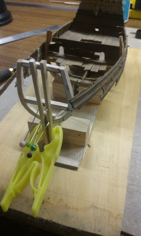
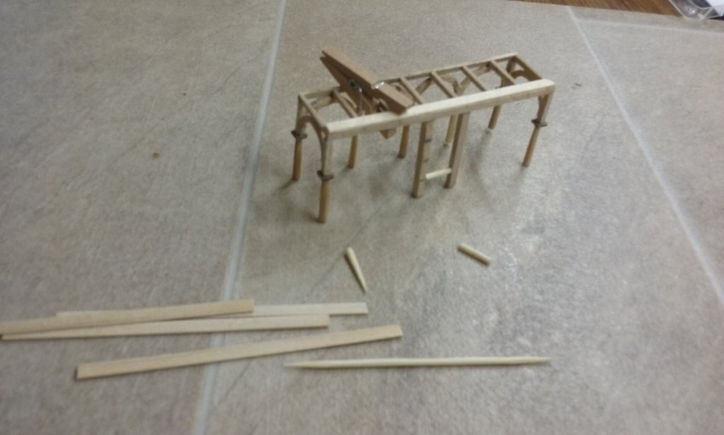
Thanks for the likes. I discovered I'd made the frames too narrow for a smooth curve of the hull where they were supposed to be. Not too much of a problem - I just moved them sternwards till they fitted within the curve. The furthest aft frame stayed where it was and I glued it in place. I had to work out some sort of temporary jig to get it square to the hull and the keel - voila! Pins and a couple of bits of balsa. Clamped the jig to the keel with a clothes peg and glued the frame in place. When I wanted to remove the jig, I just pulled out the pins. Then I clamped the existing planking to it with clothes pegs to get the curve I wanted, placed the next frame so it just reached the inside face of the planking on both sides and glued it in place using the same type of jig. And same technique with the third frame from the stern/ Now I need to make some more, wider frames, which will fill the gap forrard of the ones I relocated. Steven


- 740 replies
-
- 16
-
-
- Tudor
- restoration
- (and 4 more)
-
Beautifully clean, precise work, Peter. And she looks good, too! Steven
- 236 replies
-
- 1
-
-
- artesania latina
- kitbashing
- (and 2 more)
-
A nice bit of history. I think I've been to Esperance once, many years ago. Steven
-
- 2
-
-
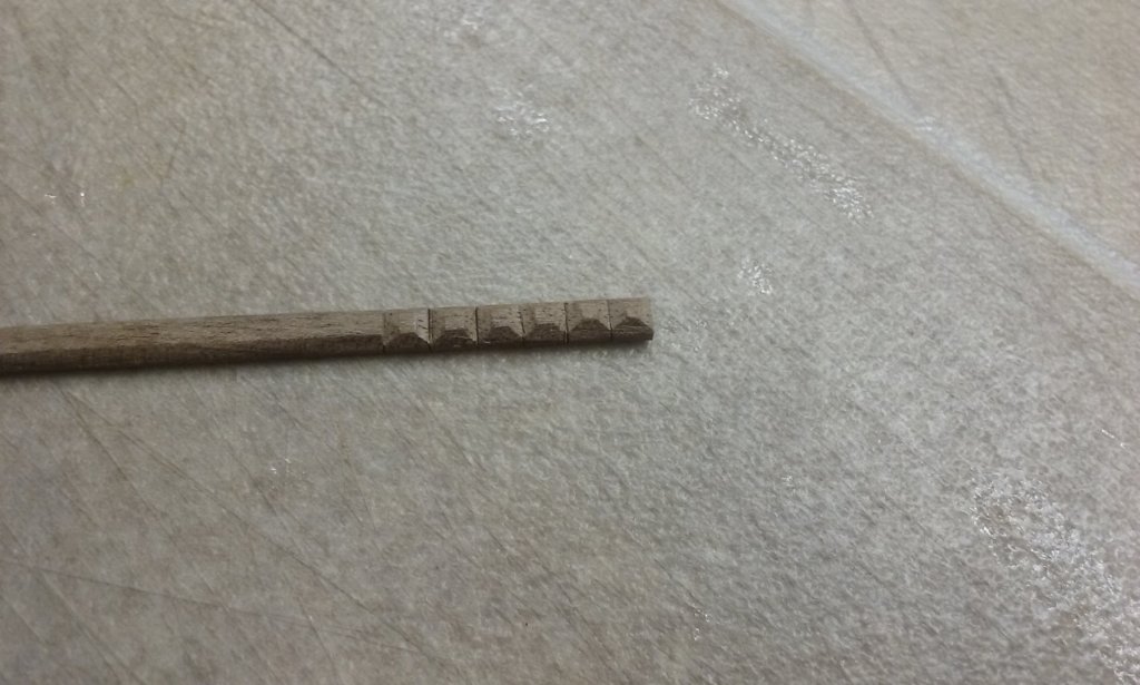
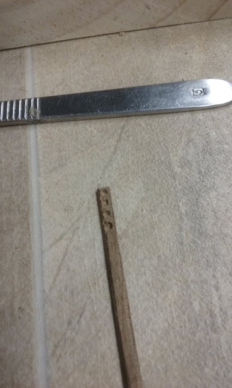
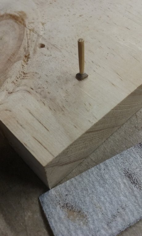
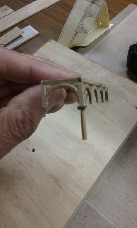
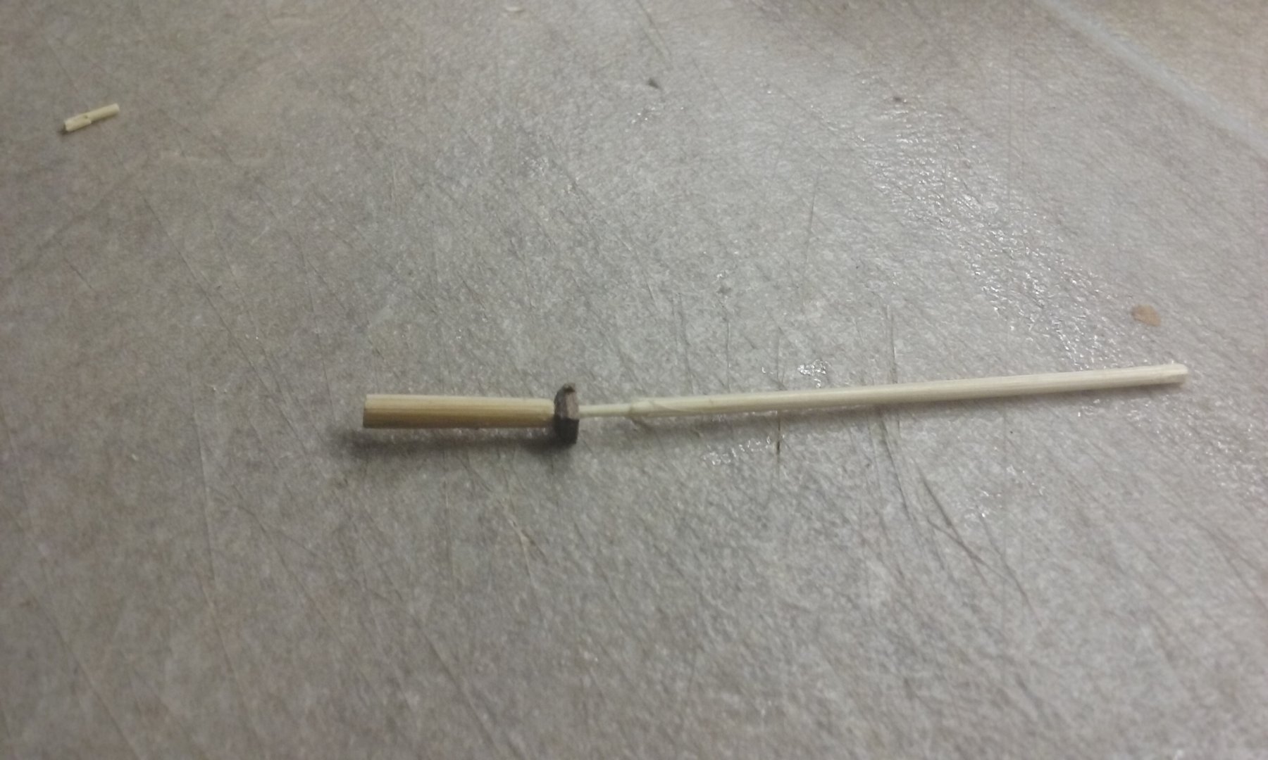
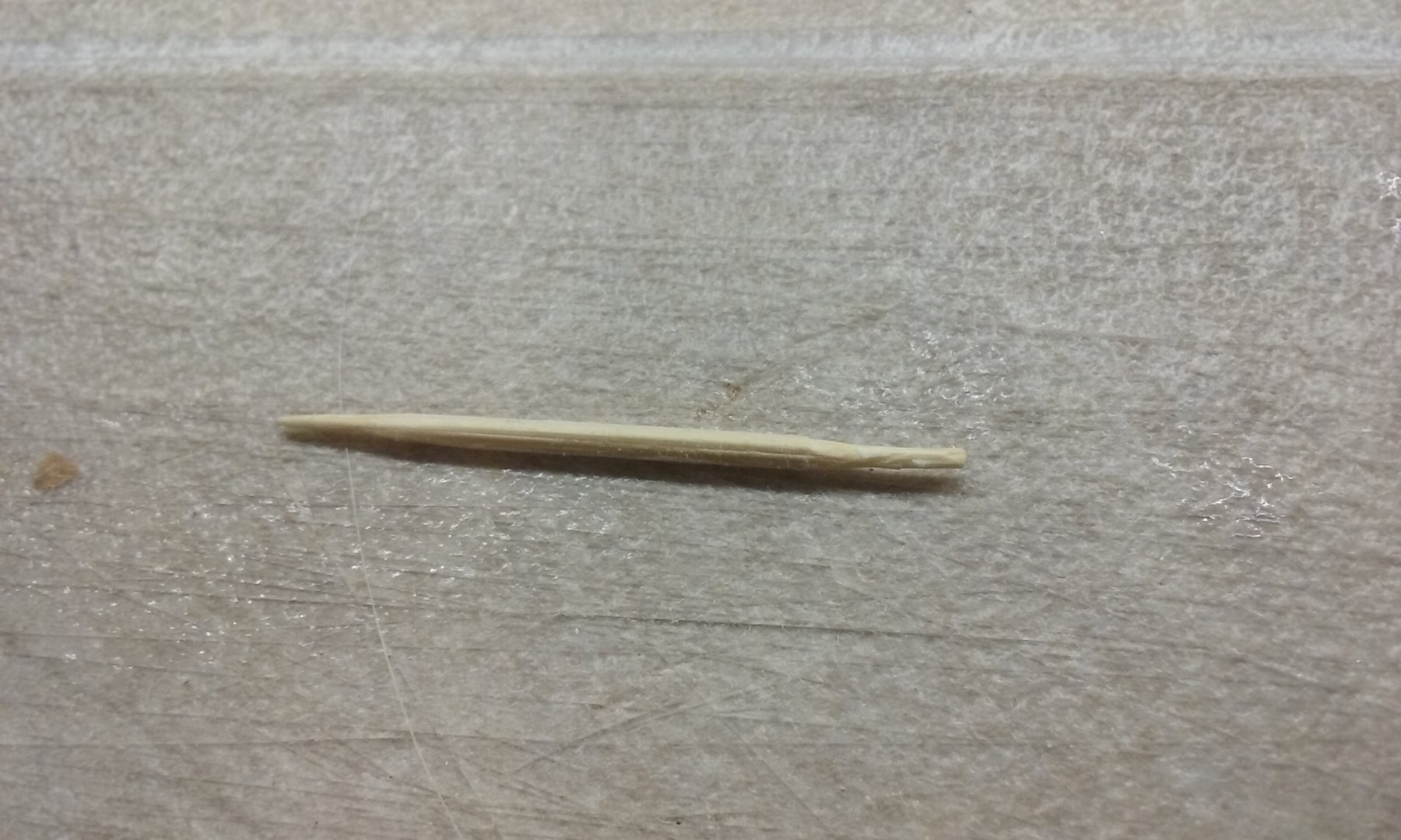
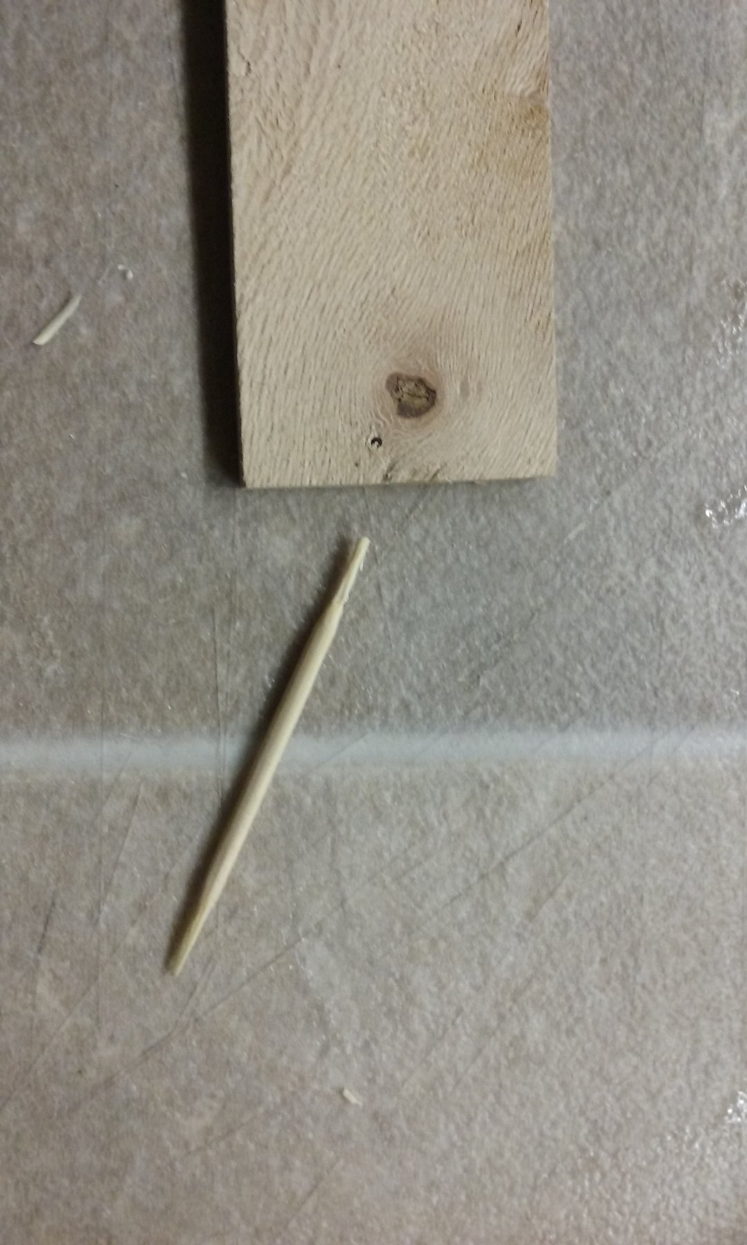
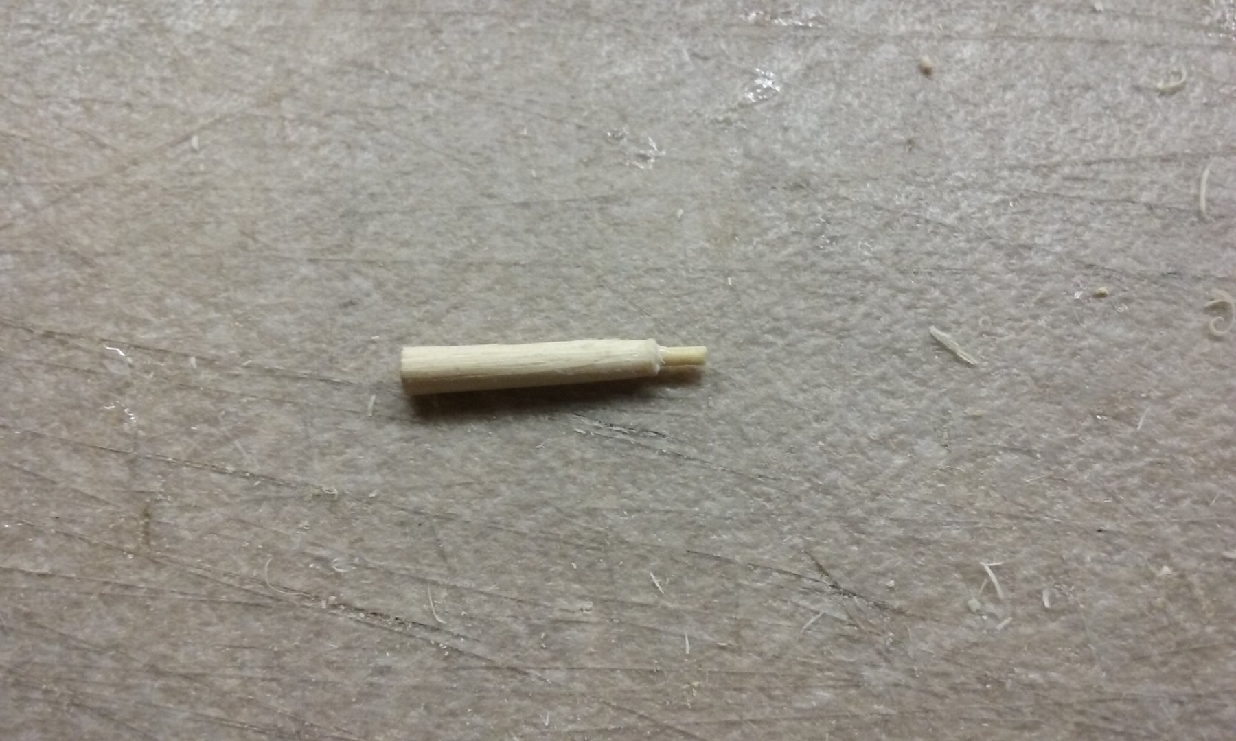
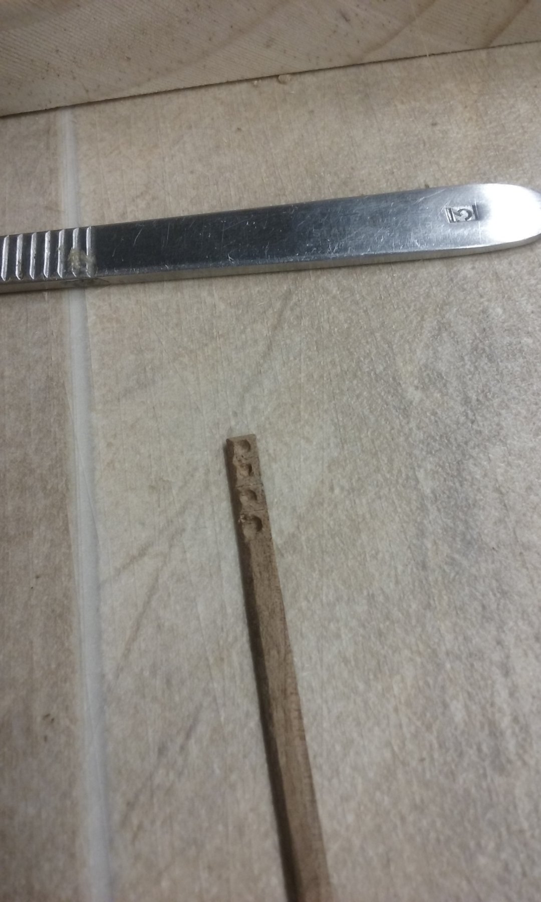
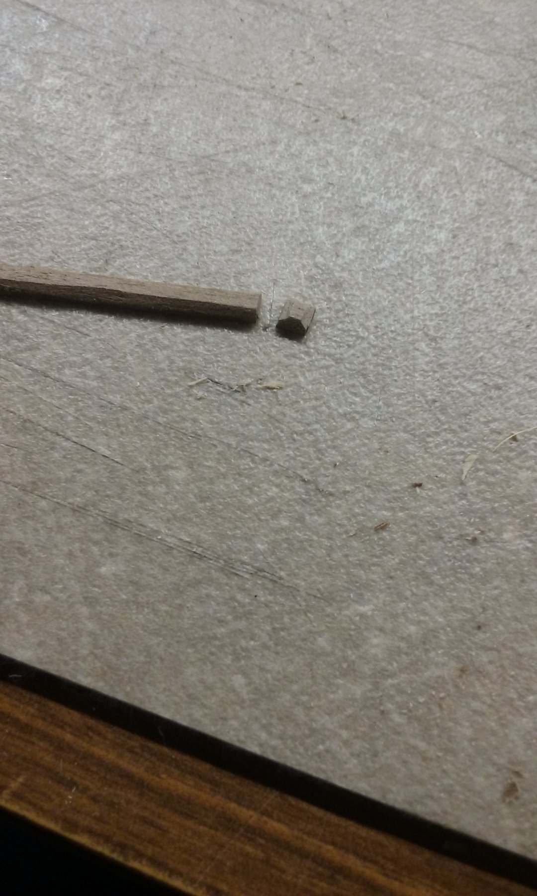
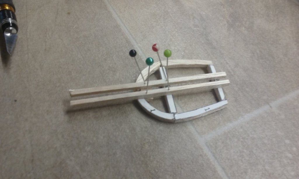
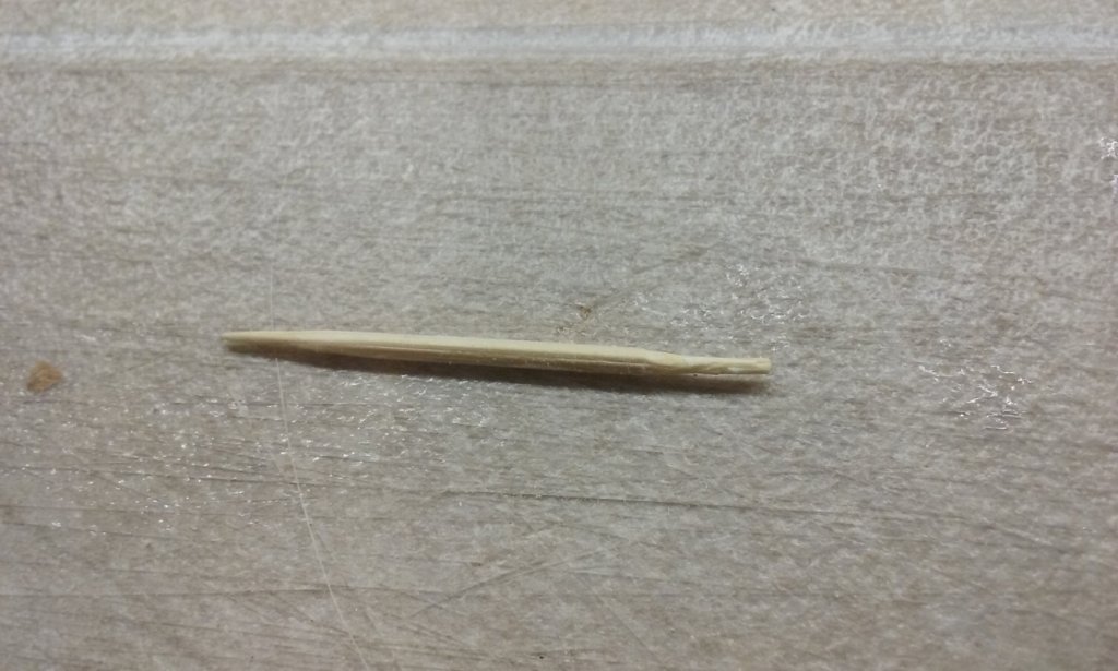
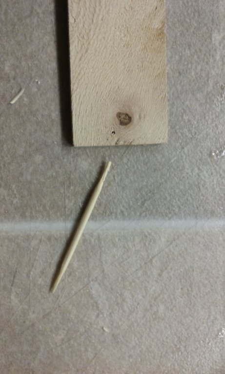
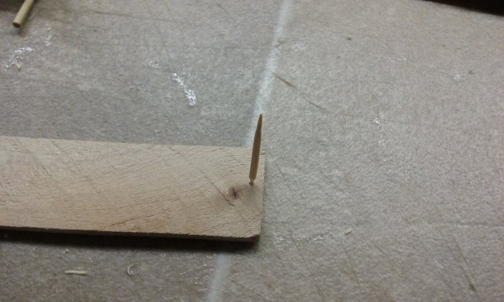
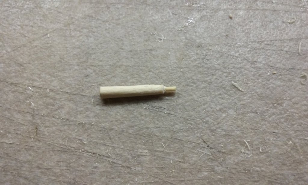
A problem from an earlier step got in the way - the tops of the columns were only butt-jointed to the rest of the assembly. Look at what happens when you use flexible PVA (white) glue. I had to use some kind of pin or peg to join the columns to the rest of the assembly. The smallest drill I could get was 1mm, so I needed a 1mm peg. Couldn't find any, so I made my own from bamboo toothpicks. Size checked against a 1mm hole. Peg inserted in a hole drilled in the top of the column and glued in place. Hole drilled into the capital and the xylokastron framing above it. Peg inserted and glued into the hole in the capital. A bit labour intensive, but it seems to have worked. Pushing the outside of the envelope, though, with the (pretty basic) equipment I've got. Getting the holes centred and in line was very difficult. Unfortunately I can only do this at the corners of the xylokastra, where there's enough "meat" above th columns to take a 1mm hole. With the other columns I'll just have to be very careful to make sure they're vertical before I glue their bases in place on the deck of the ship. Steven


-
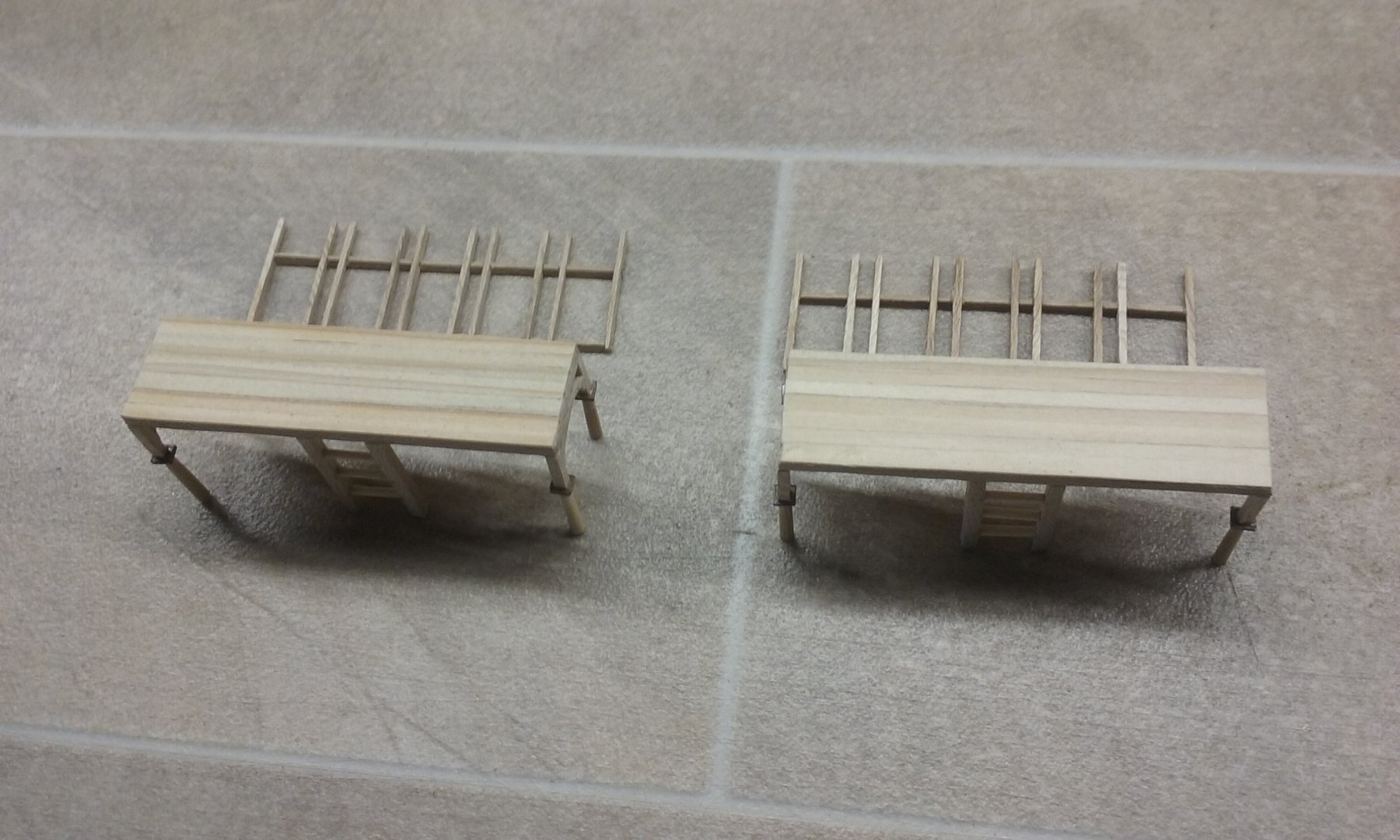
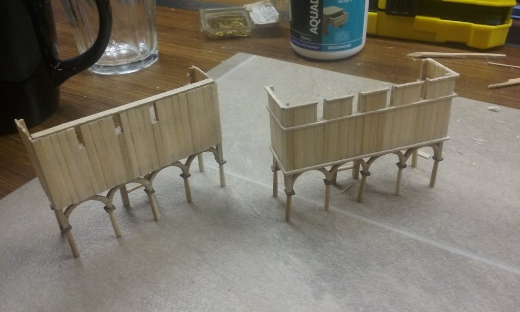
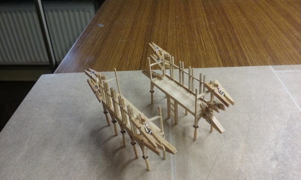
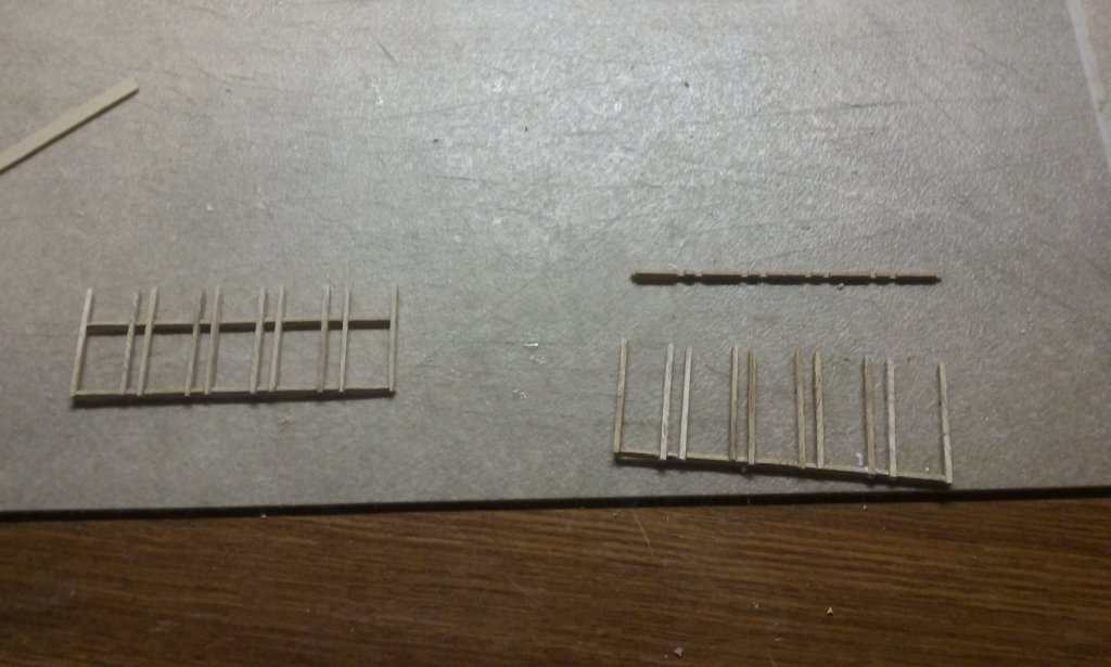
I've now added the framing for the xylokastra parapets and started on the planking. Laid the assemblies on the tabletop to glue the front parapet frames on. Here they are in place The glued the sides of the parapet frames on and held them in place with pegs. Here they are - frames complete Steven


-
There have been several repairs of old models (many of which really weren't terribly accurate in the first place) undertaken by members of this forum, often with very good results, considering the limitations of the original model. I believe yours fits in well with these and you certainly have nothing to be ashamed of in putting this log up on the scratch build section. I agree with mark and Roger - a very nice, clean and attractive piece of work. And in its own right, it's a good record of a model of a type belonging to that time and place - in itself, a piece of history. Steven
-
HMCSS Victoria 1855 by BANYAN - 1:72
Louie da fly replied to BANYAN's topic in - Build logs for subjects built 1851 - 1900
Nice research work, Pat. What a find! Beautiful fine work on those tiny pumps. Looking forward to the PE. Sometimes time apparently missed from modelling turns out to be better used put into research. Steven- 1,013 replies
-
- 6
-
-
- gun dispatch vessel
- victoria
- (and 2 more)
-
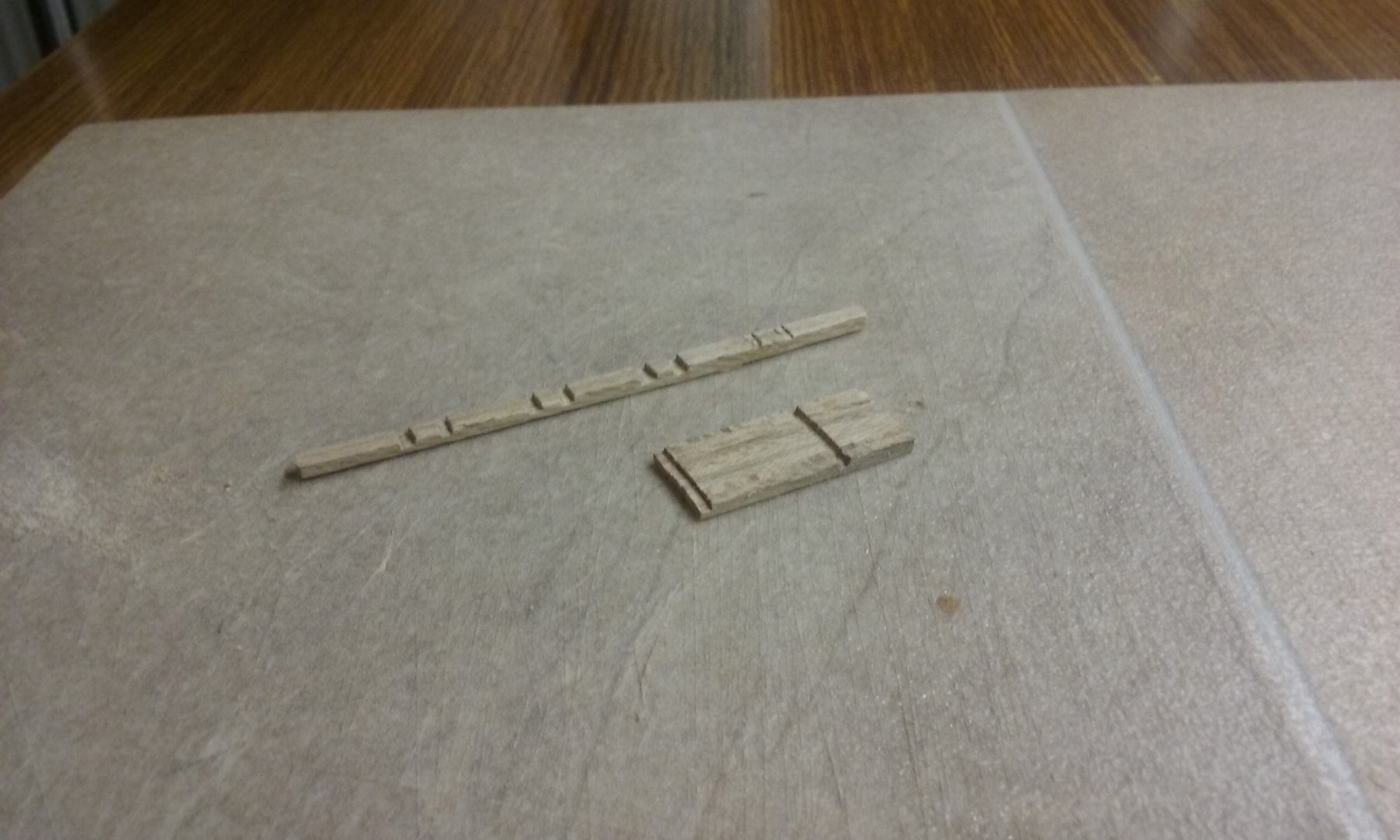
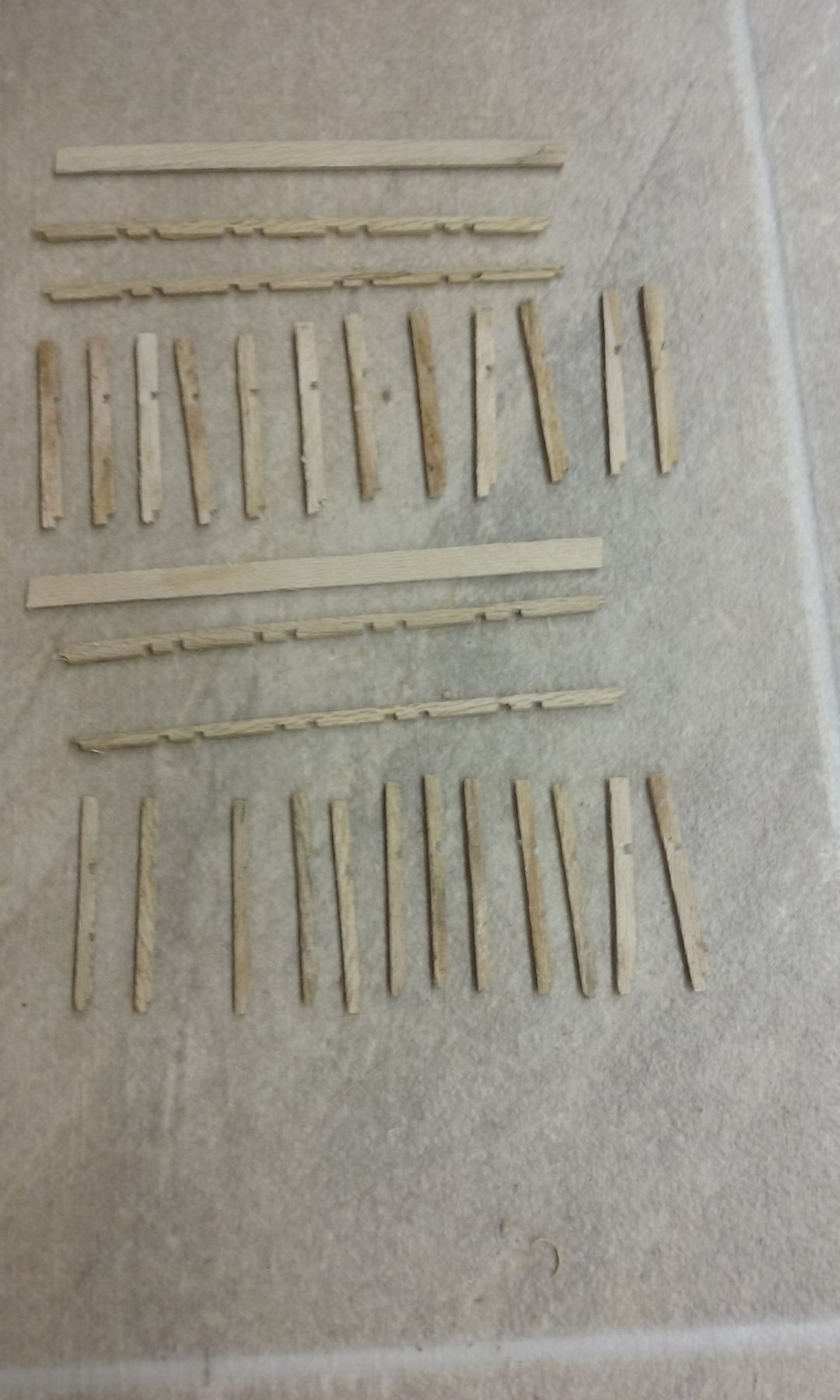
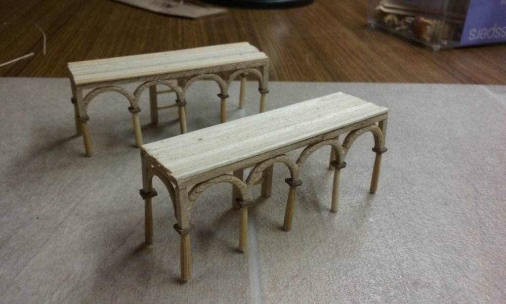
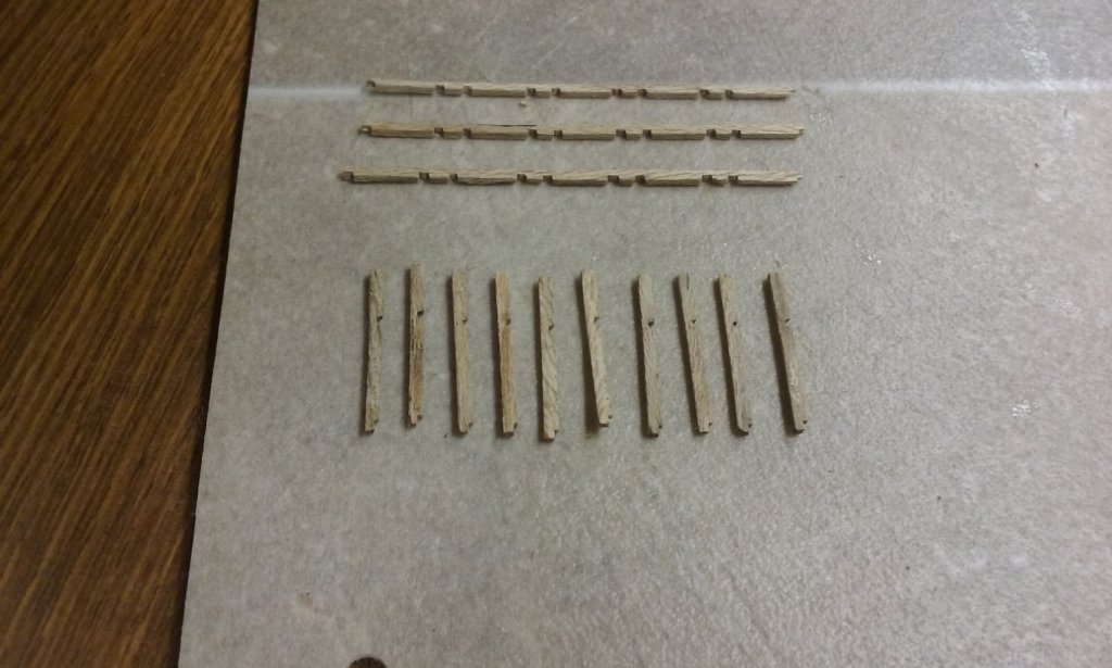
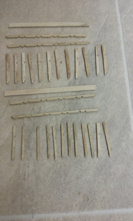
I've been working on the xylokastra. The first photo shows them with the decking added. Here is the framing for the parapets/battlements to protect the marines in battle. First the framing members were cut to shape and all the identical ones glued together - the long ones are the horizontals, the short ones are the verticals. Then grooves cut into them where the mortises were to go for halving joints. Using isopropyl alcohol the glue was dissolved and the members separated. More framing members, including the ones for the sides and top of the parapets. The frames assembled and ready to put in place. Steven

-
Beautiful work, Javier. I take my hat off to you, sir. Steven
-
The Ethel & the Ferret - a Tale of Two Ships
Louie da fly replied to Jim Lad's topic in Nautical/Naval History
Hard to be sure. I was only told about one wreck, and by someone not versed in things maritime, so I was only looking for one. But if I remember correctly, there was only one group of remains visible, so it's likely the Ferret remains were buried. The wreck is on a narrow bit of beach at the bottom of this enormous cliff. There's a timber walkway/stairway down to the beach now, but it would have been murder getting up the cliff in the day. It's now all part of a National Park, very popular with fishermen, and you can stay (if you can afford it) in the renovated cottages used by the gypsum miners. Worth a visit, but pretty bloody stark and rugged. It's all limestone just under the sand and scrubland on top. I think I saw a tree there . . .😉 Steven -
The Ethel & the Ferret - a Tale of Two Ships
Louie da fly replied to Jim Lad's topic in Nautical/Naval History
I was there a couple of years ago and saw and walked around what was left of the Ethel. A very inhospitable coast. Never thought I'd see it on this forum. Steven -
Very true, Patrick. It's happened to me too. Unfortunately I can't get plastic clothespegs this small, so I have to go with wooden ones. Steven
-
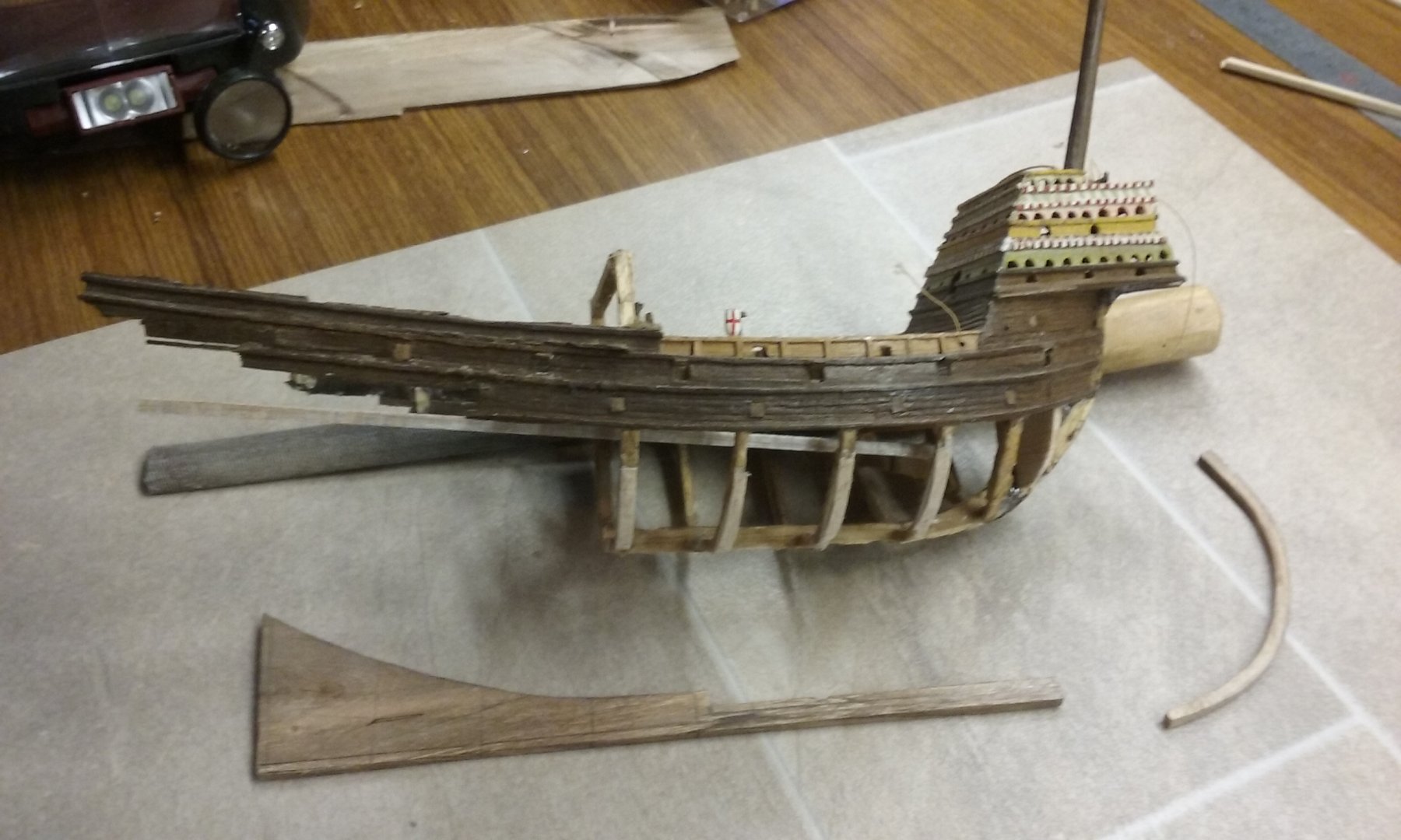
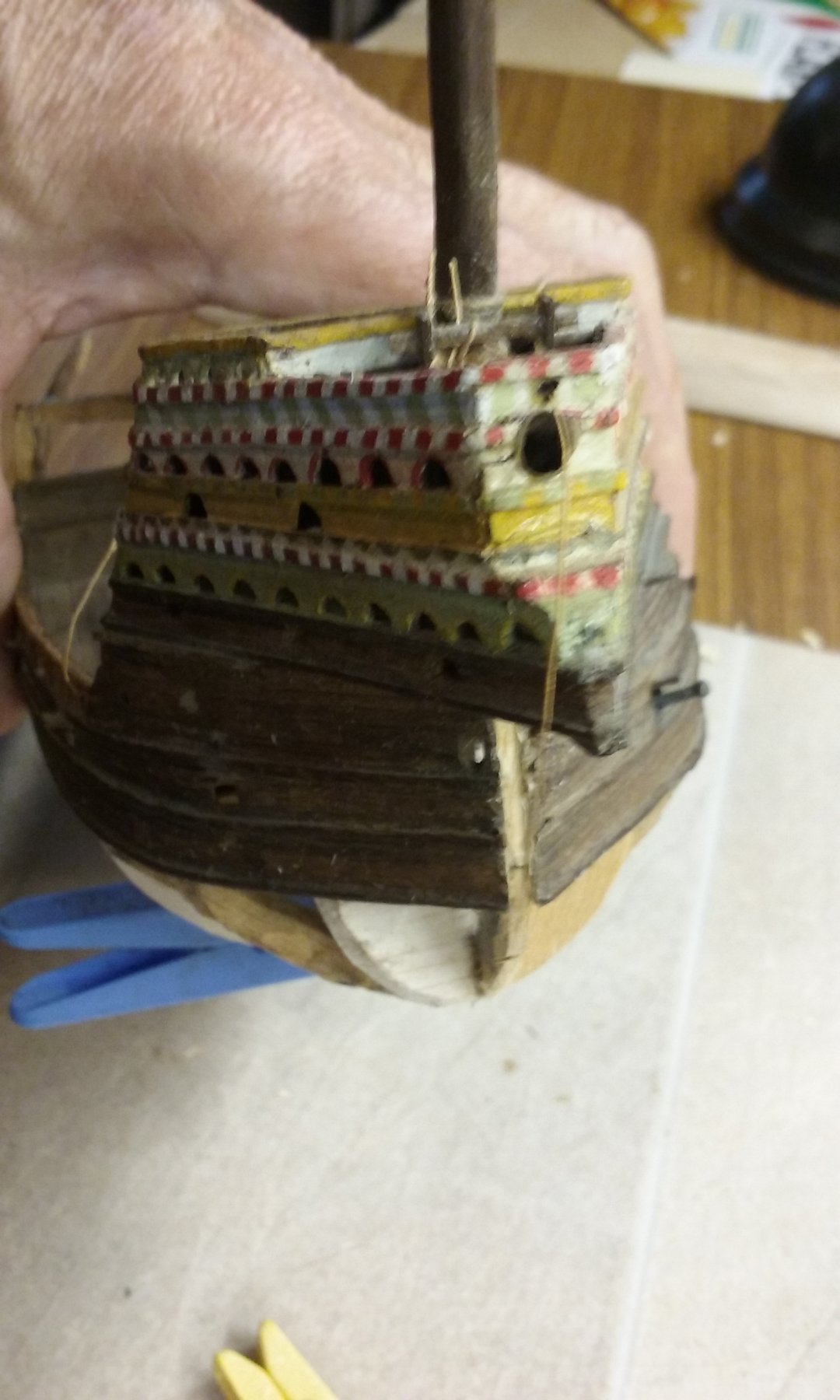
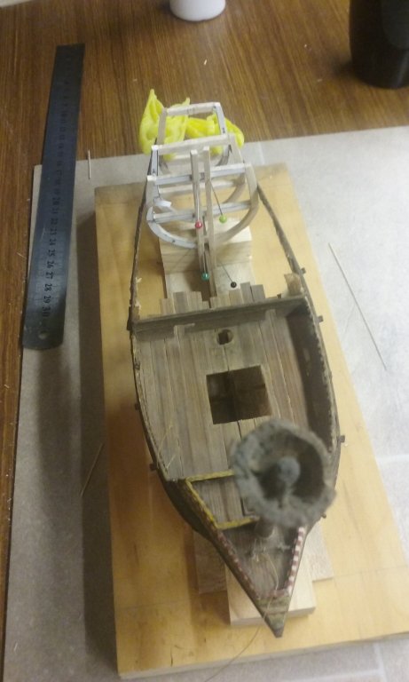
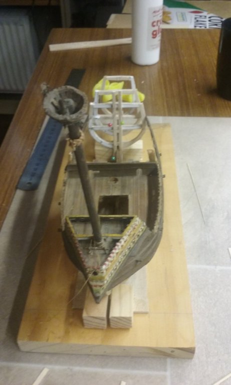
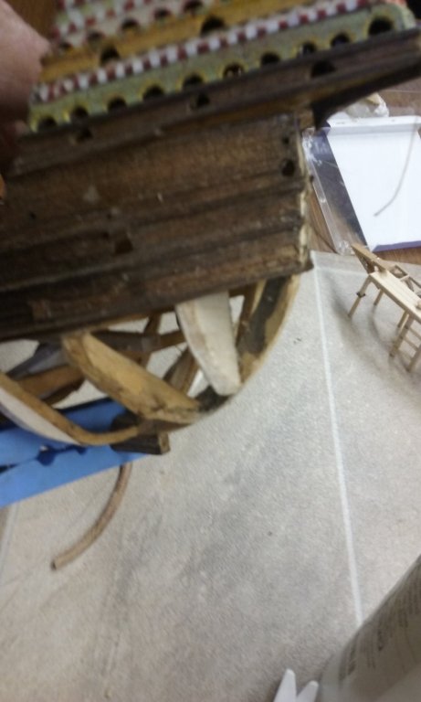
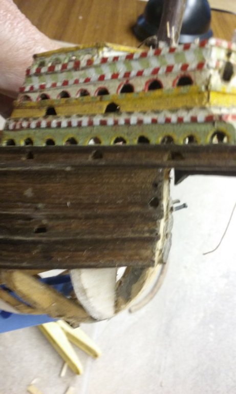
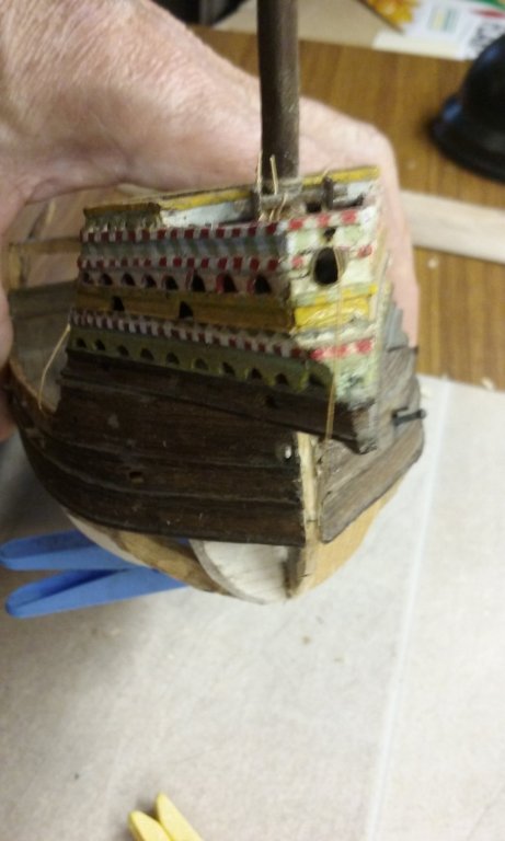
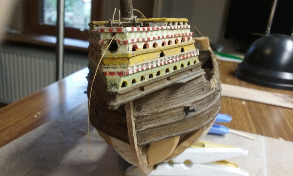
I've cut away the stern section of the balsa keel so I can replace it with the new walnut one, which you can see below the ship, along with the new stempost in walnut. I'm leaving part of the balsa keel in place where there are already existing frames which aren't to change, and cut it back level with the bottoms of the existing frames so that only the new walnut keel will show. I've shaved the old stempost down to allow a "slot" for the new exposed walnut one to fit into. Here's the new stempost and keel dry fitted. The keel is still a bit too thick and needs to be thinned down before gluing can take place. You might be able to see a small gap between the stempost and the forrard end of the keel. I've since fixed that using a bit of trimming and juggling back and forth. And here is the new stempost from forrard (still dry fitted). There was a lot of trial and error getting the new pieces to fit smoothly, but it all worked out in the end. Steven


- 740 replies
-
- 10
-
-
- Tudor
- restoration
- (and 4 more)
-
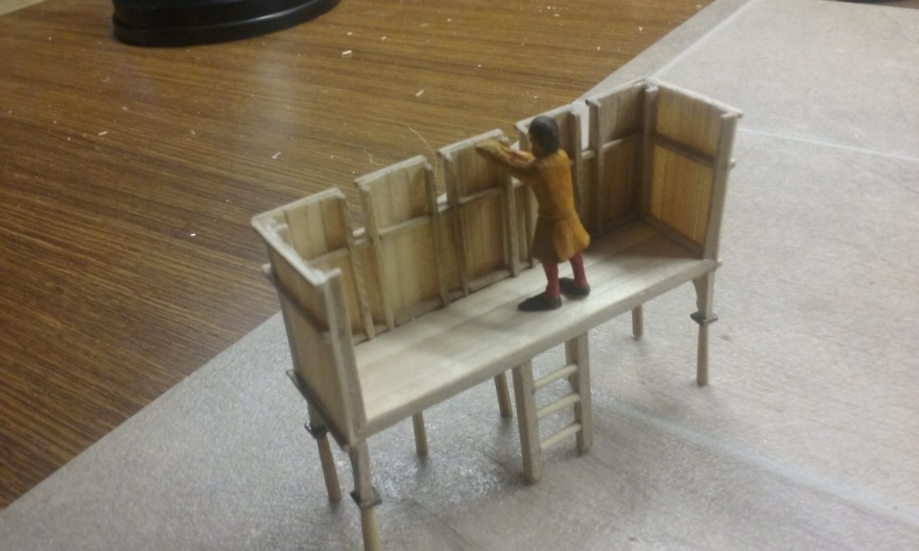
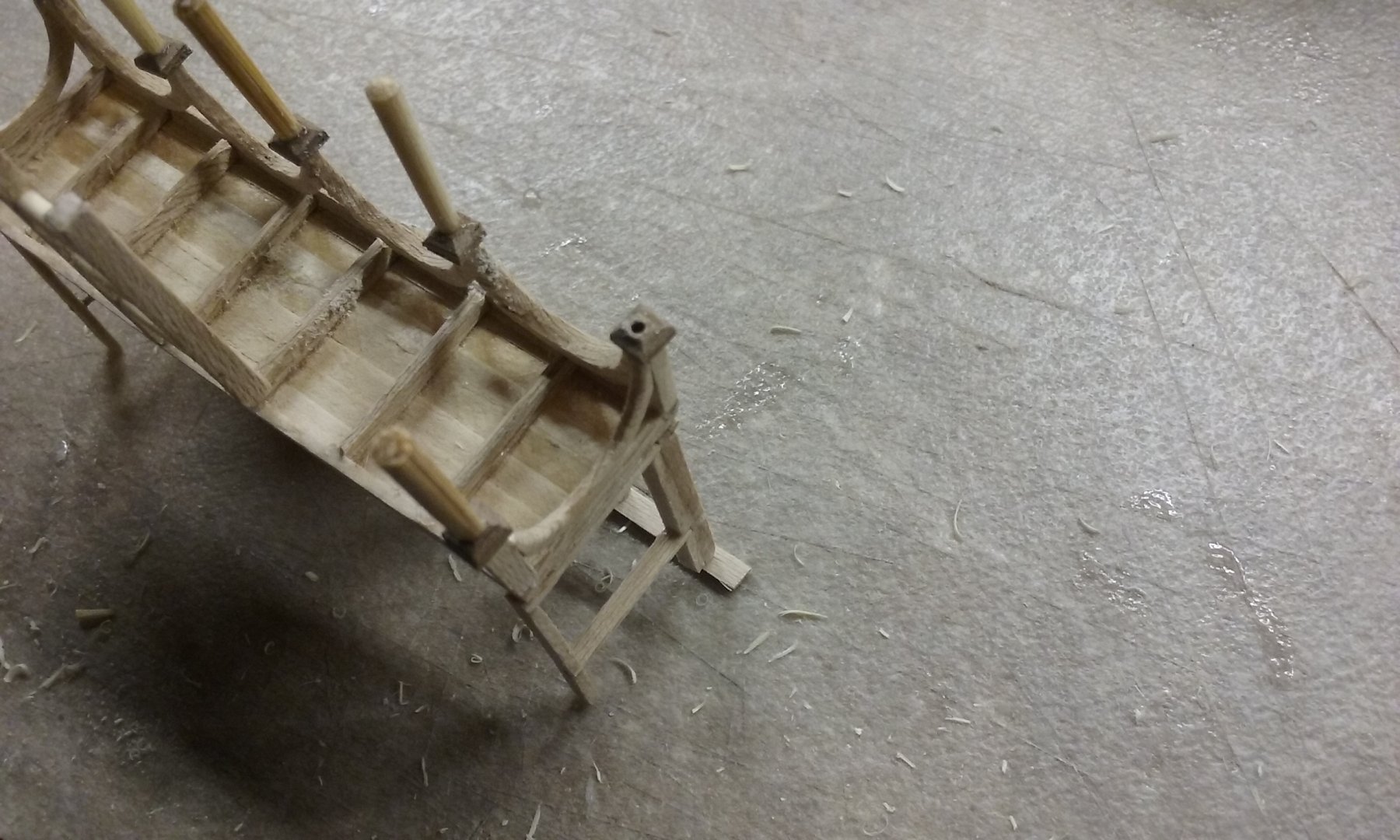
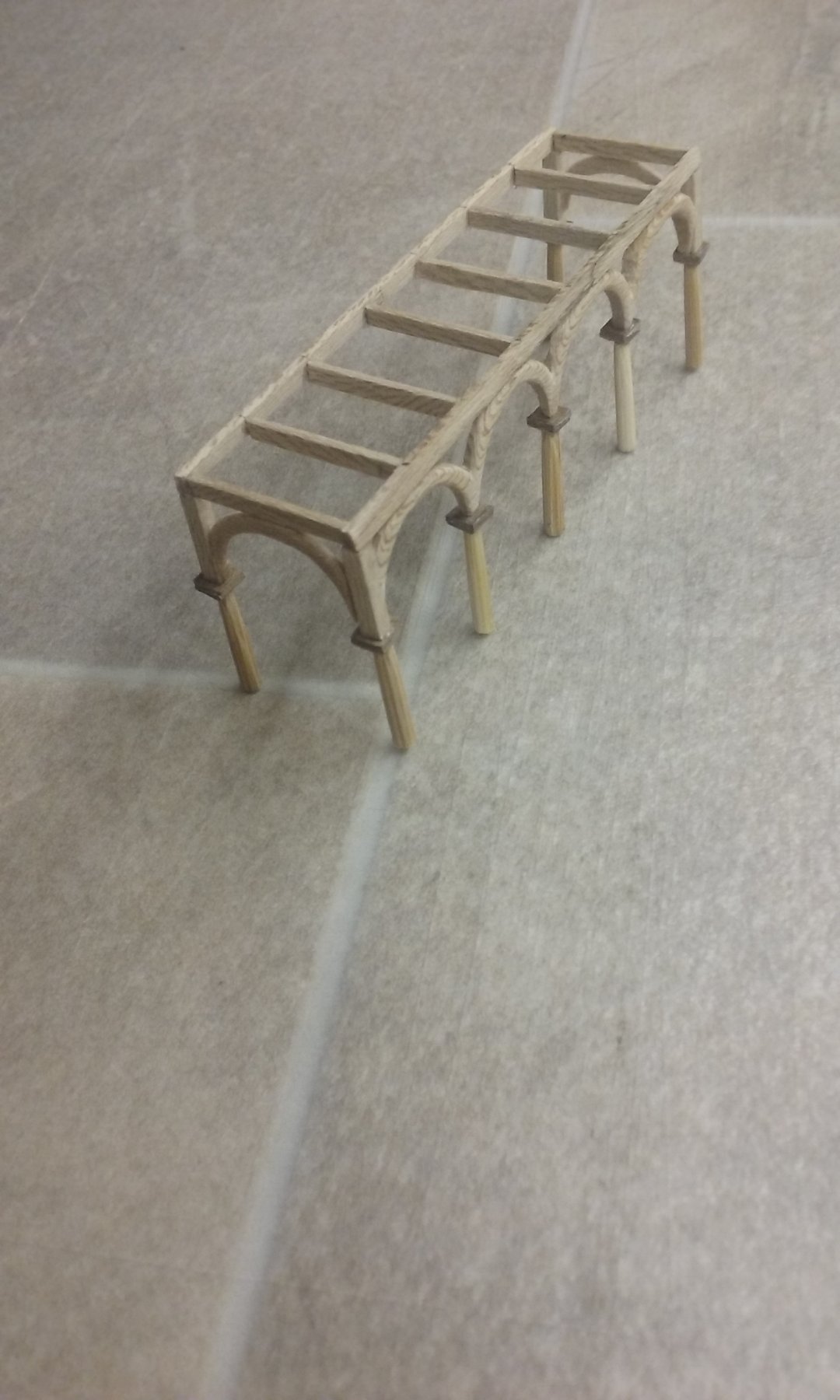
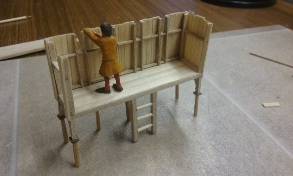
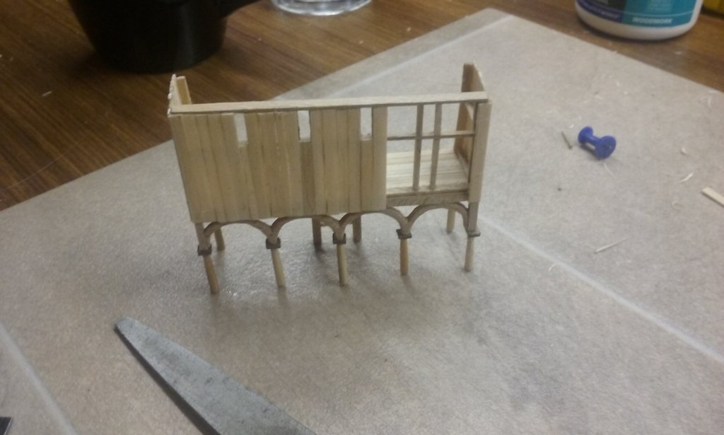
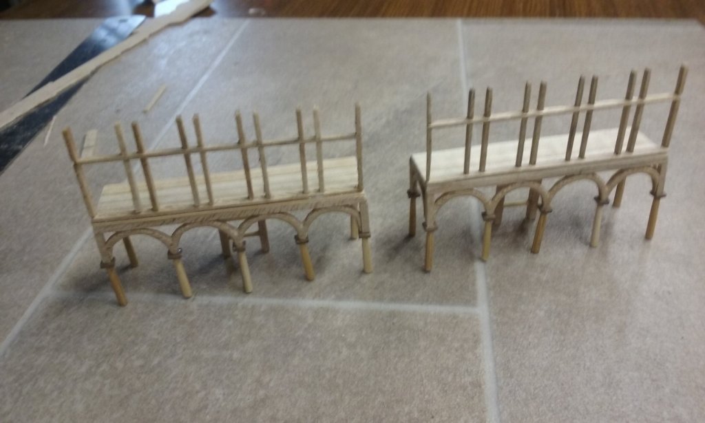
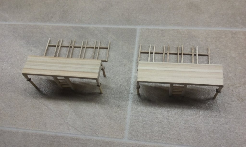
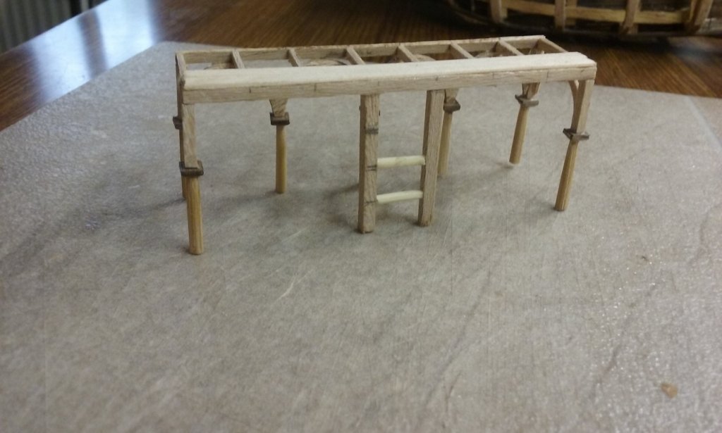
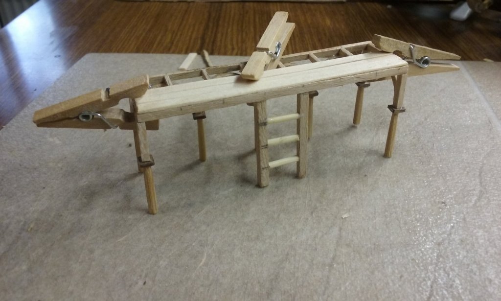
Adding decking and ladders to the xylokastra. The uprights of the ladders double as supports for the beam carrying the rear of the deck. (The rungs are made from toothpicks). Steven
-
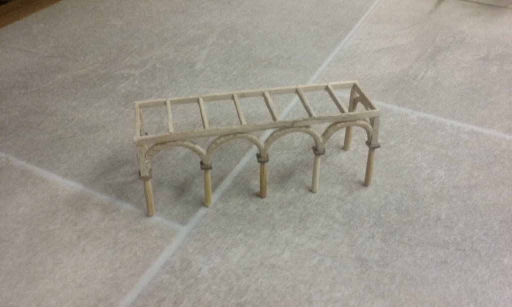
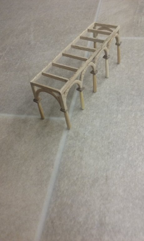
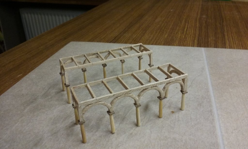
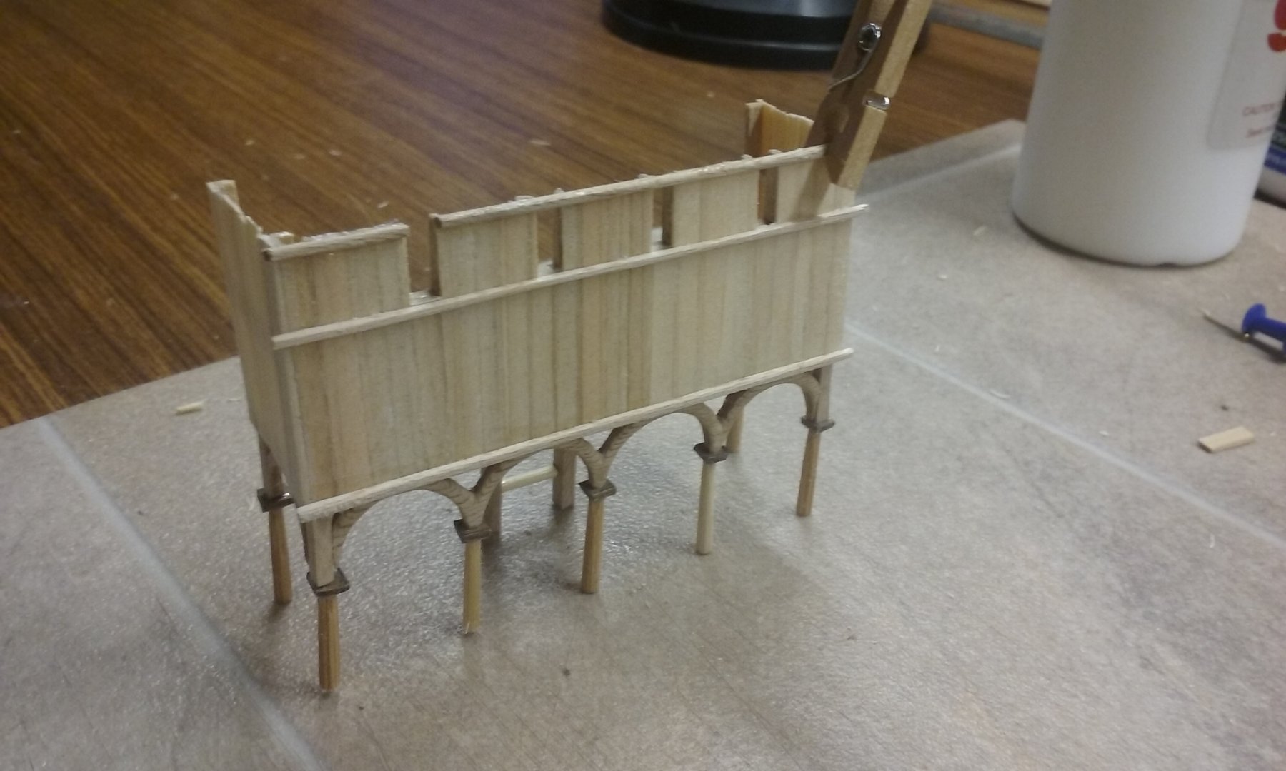
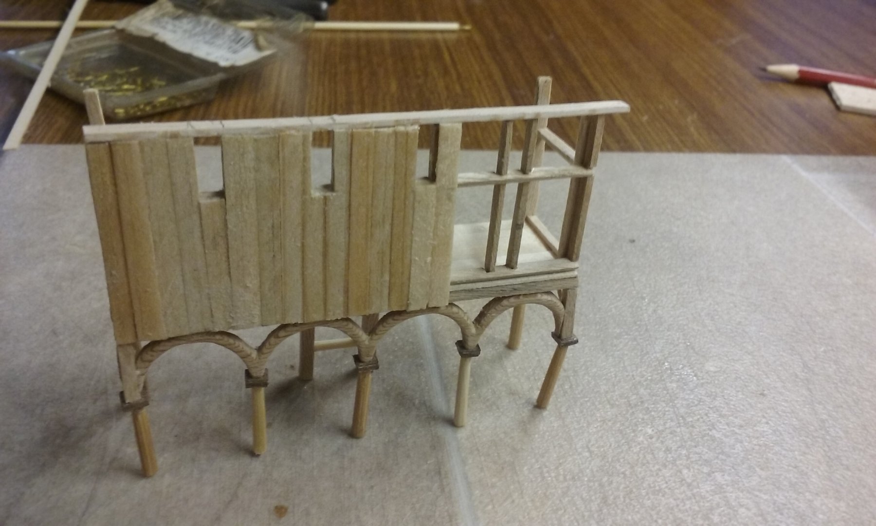
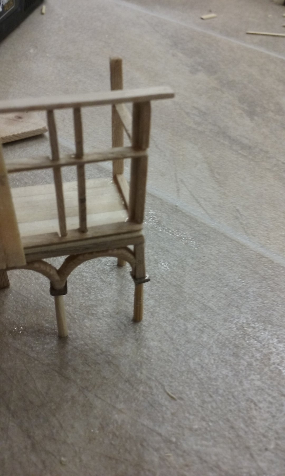
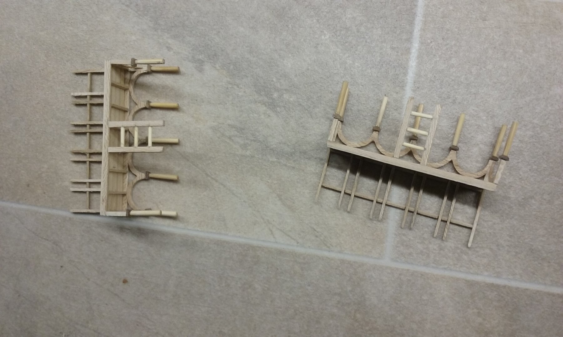
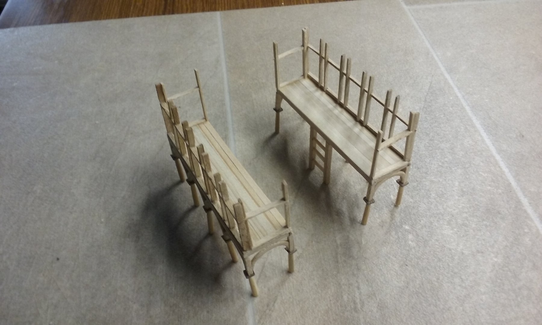
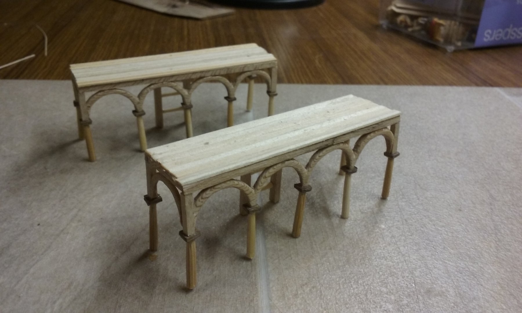
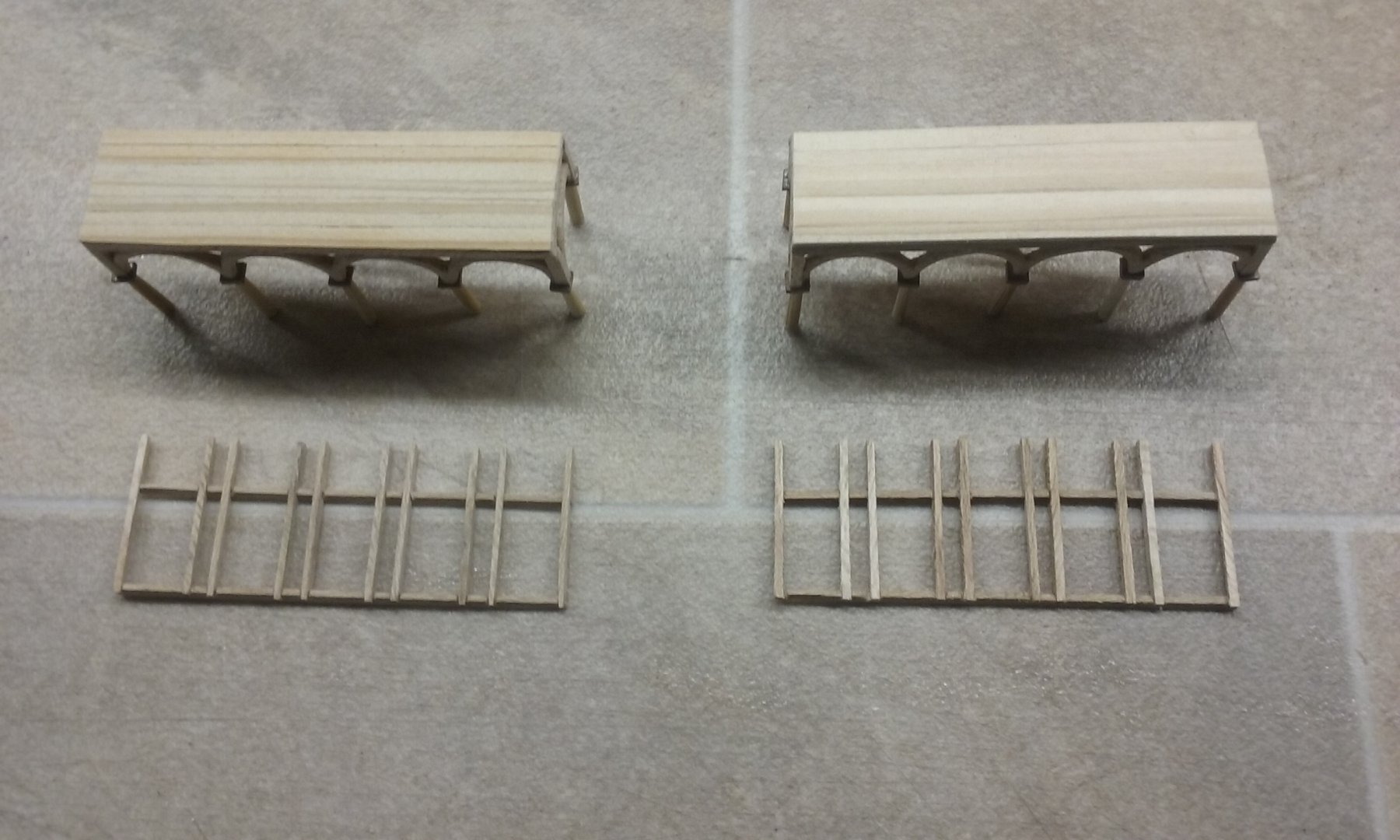
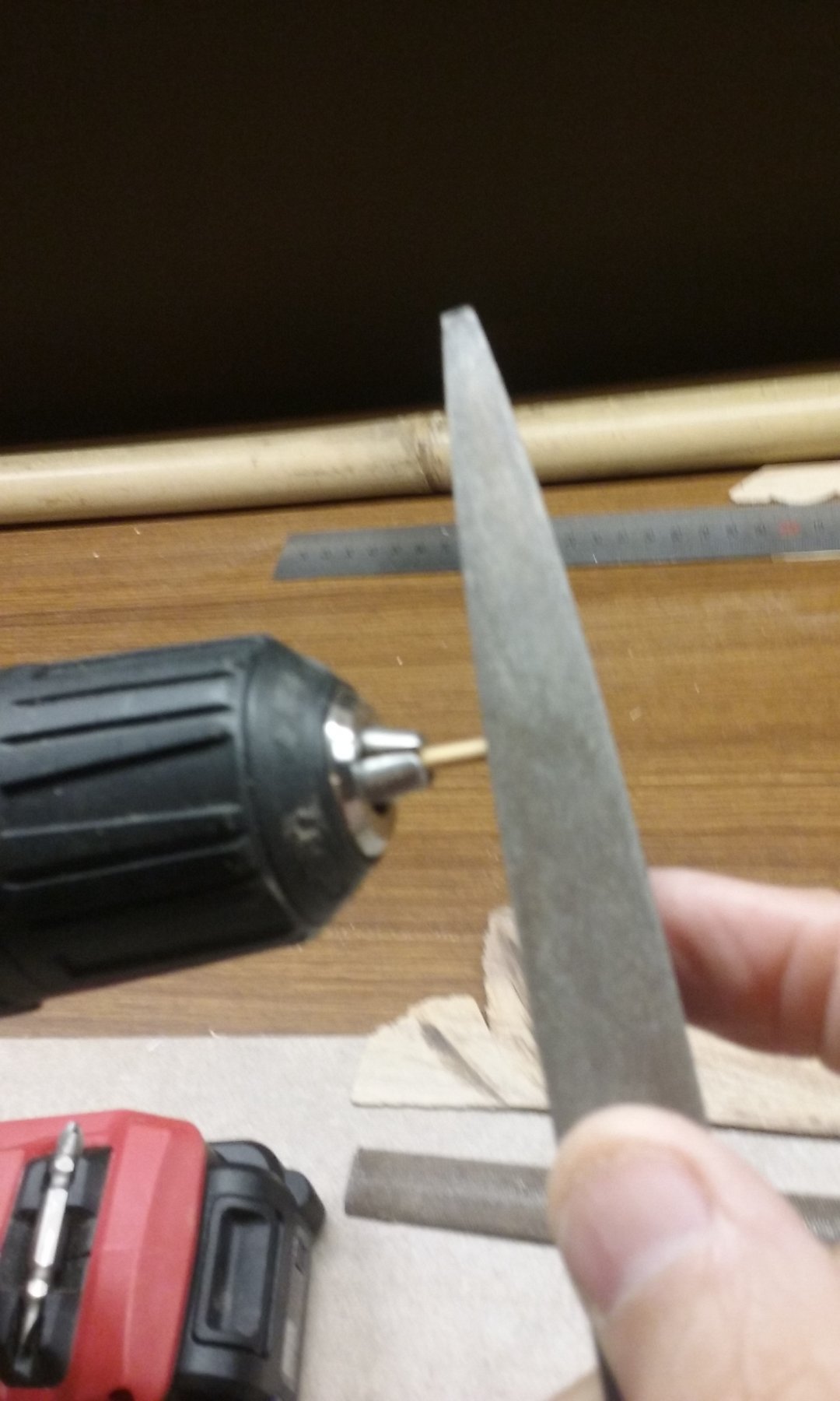
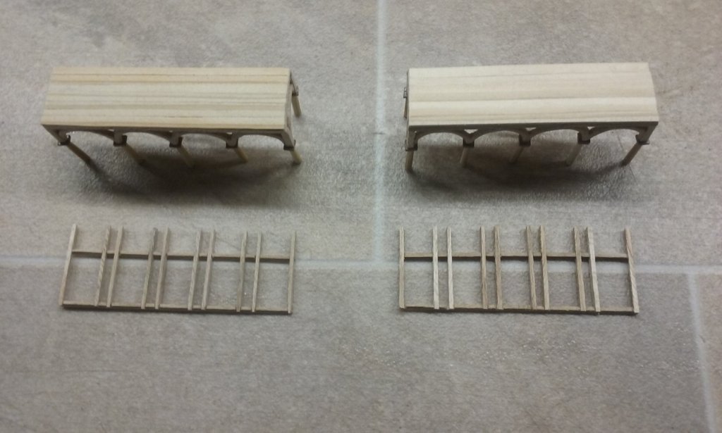
And here is the next step in the making of the xylokastra. Supporting columns for the arcades shaped from bamboo skewer, using an electric drill as a lathe Capitals made for the columns Capitals attached to the columns and then attached to the arcade Here's one of the xylokastra with all the columns in place. Butt joints throughout - mainly because I couldn't think of a sufficiently precise way of fixing everything at right angles and in the proper place. I tried drilling short holes in the lower side of the capitals to act as mortices to take tenons at the tops of the columns, but I just couldn't do it precisely enough, and had to throw them away and start again. However, the PVA glue of the butt joints is slightly flexible, so I can adjust the angles of the columns until everything is square. And here are the two xylokastra with all columns in place. Next is to make their "wooden walls" and add the raised decking for marines to stand on. Steven