


GuntherMT
-
Posts
2,213 -
Joined
-
Last visited
Content Type
Profiles
Forums
Gallery
Events
Posts posted by GuntherMT
-
-
-
Thanks Frank. Once I get back to this I'll see what I can work out, and maybe borrow that stuff from you. I don't have a big rush to finish the guns, since they wont' be put on the ship until it's complete anyway, as I'm sure I'd break them all!
After looking at Dan's Vulture build today, I may try to make rounded yokes like he did, they will probably look more realistic than my squared off one.
- GLakie, thomaslambo, zoly99sask and 1 other
-
 4
4
-
-
Cool, I've just never seen one rigged that way, so it looked 'wrong'. Certainly doesn't mean it is, as I'm sure there are a bunch of ways to do things 200+ years ago that I've never seen either. As long as you like it, then it's perfect!
It looked good but what I didn't like about it was the end line was attached to the outside of the ship. That didn't make sense to me.
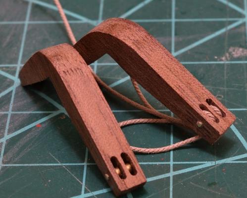
For my catheads & the end line, what isn't complete in the photo I posted is another hole just behind the sheaves (I had forgotten to drill it before the picture). The rope starts at this hole with a stop knot, then runs down through a double block with the hook, then back up to the first sheave, then back down to the double block then back up to the second sheave and then is belayed to a cleat or timber head on the bulkhead.
- mattsayers148, mrangus and GLakie
-
3
-
Thanks Alistair, good idea, but the brass rod I am using is sized to fit perfectly into the brass tube that I've inserted into the pedestals to mound the guns, and using the PE would probably not fit properly (although who knows!).
I think for this build I'll work on refining my yokes by shaping the tops a bit. I plan to blacken all of the assembly when done, which should mute the entire assembly to the human eye a bit. That PE yoke does look great though, definitely going to file that away in my head for the future!
Feel free to leave the photo, it's fine for people to get other (better) ideas when reading through the log.
Thanks also for the rope on the mast wedge trick. I haven't ever seen that done, but looking back at your photo's, it looks good! I even have dark brown rigging rope to use for that, since I was planning to leave the wedge natural walnut like all the other walnut on the boat.
- thomaslambo, GLakie and KenW
-
3
-
Good to see you around Alistair, and yea, I've stuck the bowsprit assembly and main mast on already, it's pretty awesome the size jump.
I continue to put off doing the chain plates on the port side, and have done some experimentation (failed) and various small bits.
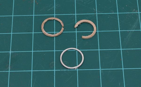
First, I decided to continue on my route of replacing most of the cast pieces in the kit by making my own mast hoops out of wood. Unfortunately, this didn't work out so good, as the wooden hoops are just too fragile, and I can't get them cut off without breaking them. This is partially because of their small size, and partially (or maybe mostly) because I was using a dowel as my wood, and the grain is just too big for this sort of thing. I have an idea on how I could make it work using multiple pieces of boxwood laminated together with the grain all going the proper direction, but in the end I decided that the effort just wasn't worth it for these pieces, and the kit hoops have been primed (and now painted as well, but no photo of that).

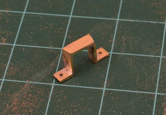
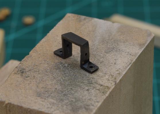
The next cast piece to get trash-binned was the strap that holds the foot of the bowsprit. This piece doesn't fit the bowsprit properly as I completed it, and it's kind of ugly anyway, so I made a new piece out of brass. This is 5 pieces soldered together, which was quite a trial, as the pieces are so small I couldn't heat one joint without breaking another one. In the end I got it done, it's not perfect, but it will do. I drilled holes for brass pins that I will make to pin the strap to the deck, and to the bowsprit. I then blackened it with Birchwood Casey Brass Black, as I can no longer get Blacken-It at the local shop.
I got the mast wedge filed to fit the mast, and rounded the outside edge. Haven't decided yet on any detailing for this piece.
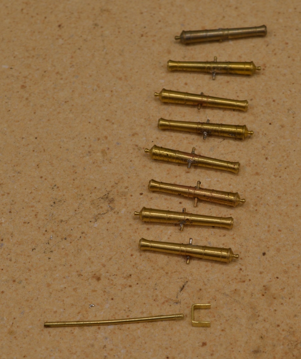
And finally, tossing the cast swivel guns into the bin, I started work on the replacements. First I soldered the trunions in place, and began to form a 'yoke' to support the gun.
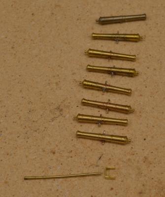
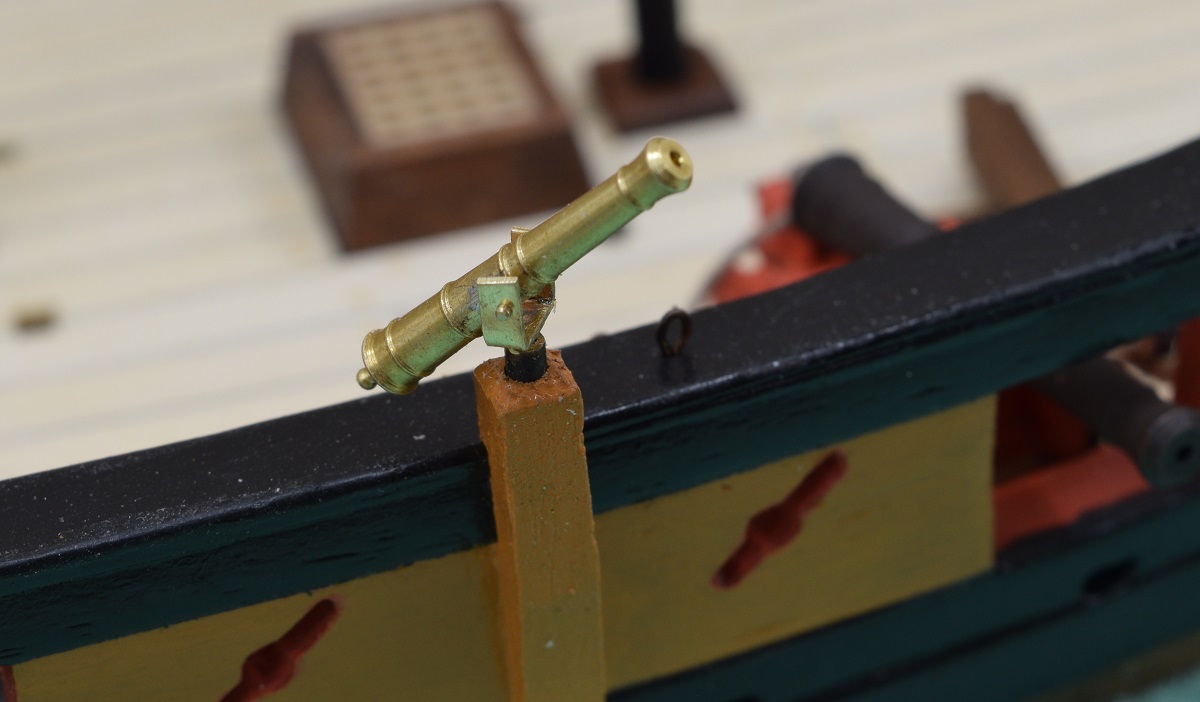
I then soldered the yoke to a rod, drilled holes for the trunion, and stuck a gun on to see how it will look.
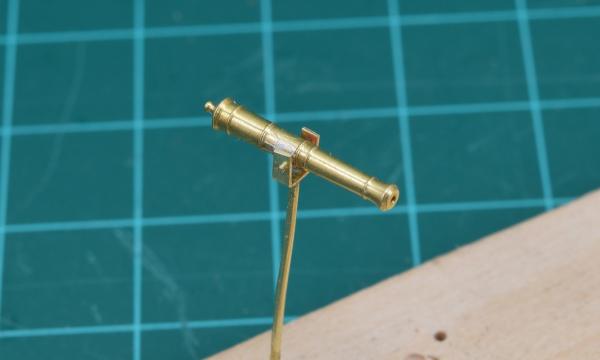
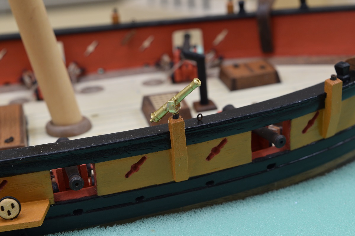
Pretty happy with how these look. Worth the effort and expense. Opinion time - should the yoke drop right down against my existing post mounts I've made, or should the rod stand them up slightly from the mount base?
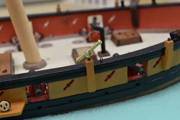
I will also be adding a handle to the gun. I sort of completely forgot to do that. Doh!
Another question. The yoke is so small, that I don't think I'll be able to solder the trunions to the yoke without breaking the existing solder joint of the yoke to the rod. Thoughts on 'fixing' the gun in place? Super glue should work I suppose, but I'm not sure how easy that will be to make invisible, and would need to be done after blackening. I'll play with some ideas, but more than open for suggestions on this!
-
It's looking great, and I hate to point this out after you made such nice straight holes, but I've never seen catheads with the sheaves that way. They would typically run 'along' the cathead, not side to side. Like this:
Of course, there are exceptions to every rule, so maybe this is the correct way for this particular ship? If you are happy with the way they look, chances are that very few people who aren't into this hobby will ever notice, but I wanted to point it out now, before you get further along in case you decide a re-do is in order.
Good luck!
-
-
-
I have a chart of what size each bit from #80 to #60 is supposed to be, and I just use digital calipers to measure the bits to get the right size for the hole I want. The undersize issue seems to be common with 'cheap' micro-drills no matter where they are coming from.
For work on the mill or drill press, I also use the PCB bits, which can be had from Amazon or very cheaply on Ebay as well. PCB bits are the ones pictured above in rtropp's post. As Frank and others have said, they don't do sideways pressure at all, but they are great for use in a press or mill.
-
-
Holy crap, it lives!
Good to see you back, I look forward to seeing how the pear works for the deck planking. I imagine it should be very nice, I've never read a bad word about pear in ship modeling.
The galley hatch looks good, you got the grating right, where I screwed up my first one and had to remake it thanks to sharp eyes here on the forum letting me know I'd done it wrong.
Hope your next update doesn't take nearly as long as this one did.

- Canute, grayarea and zoly99sask
-
3
-
Brian when I see work like this it convinces me that if I ever give another ship a go, I'll have to invest in a few real power tools. Everything looks so precise....
You can get similar results (or better) with hand drills and files - there are plenty of examples of that on these forums - but I'm lazy and impatient, so I like the power tools.

- Salty Sea Dog, mrshanks, Canute and 3 others
-
6
-
Thanks all, appreciate the encouragement.
Nice work on the sheaves Brian, and the mast. First crack on that is great. Must be a pure pleasure working with Pear.

Cheers
I have no idea what it's like working with Pear, I'm using Boxwood.
- GLakie, Canute and thomaslambo
-
3
-
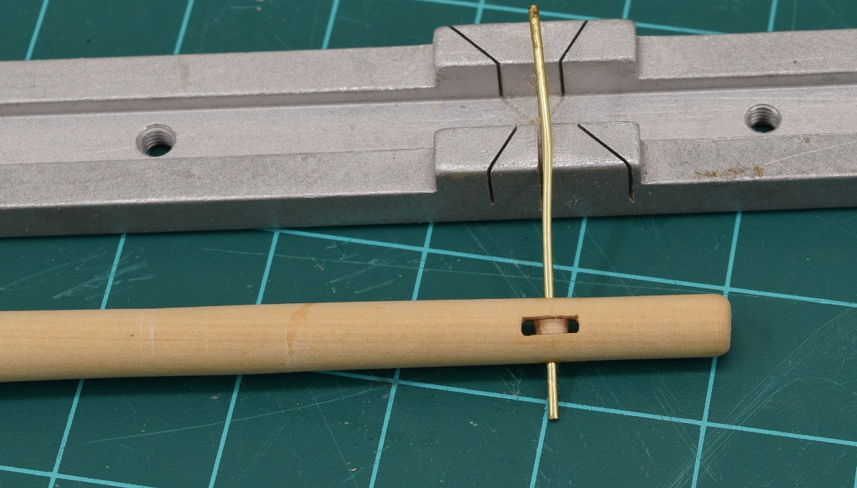
Thanks for the continued likes and comments everyone. Feel free to jump in with suggestions for improvement or telling me I'm making errors at any time. This is only my 2nd ship, so I've got plenty to learn still.
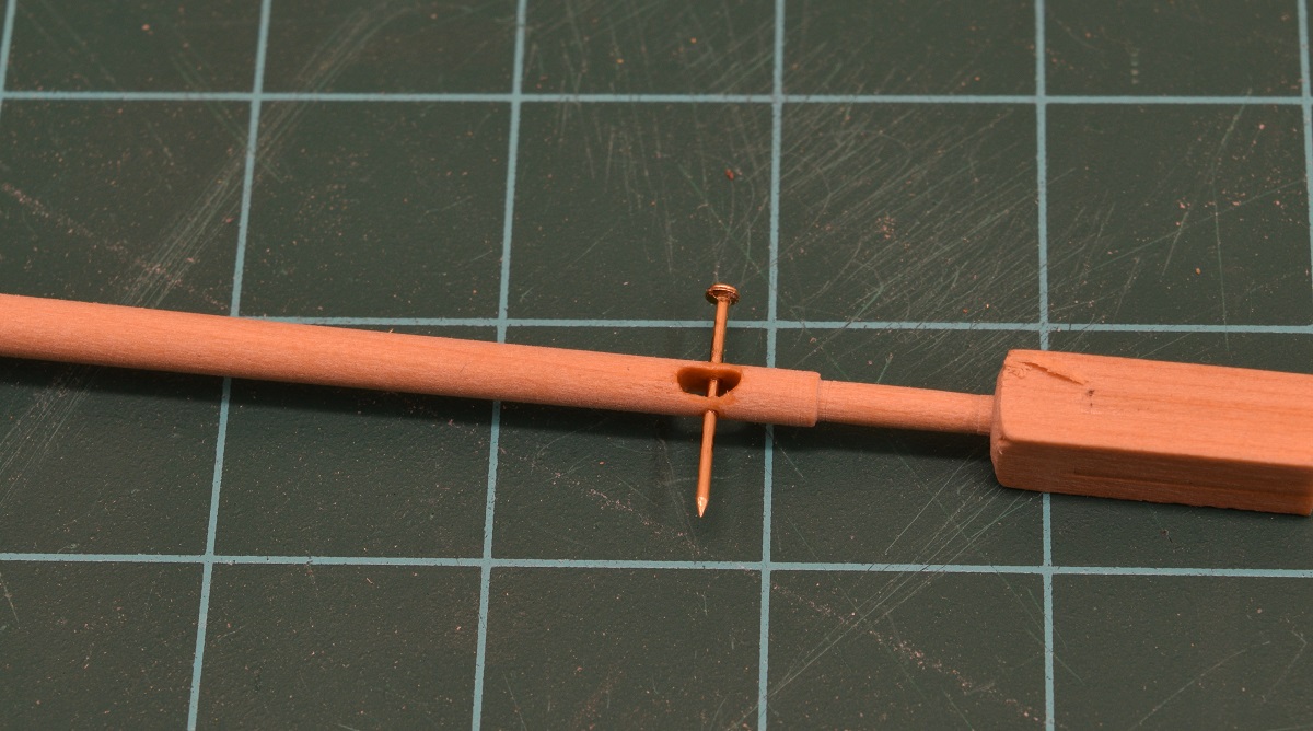
Instead of finishing the chain plates and dead-eyes on the other side of the boat, I decided to play with power tools. The plans show a sheave in both the bowsprit, and the jib-boom, but the kit doesn't provide it, and both the plans and instructions say to just drill a hole for the line to run through. Well, the heck with that, I'm an idiot and decided to risk wrecking my bowsprit by building in the sheave! I am pretty happy with how the one for the bowsprit came out, I used a small piece of dowel with a hole drilled through it and sanded down to size for the pulley.
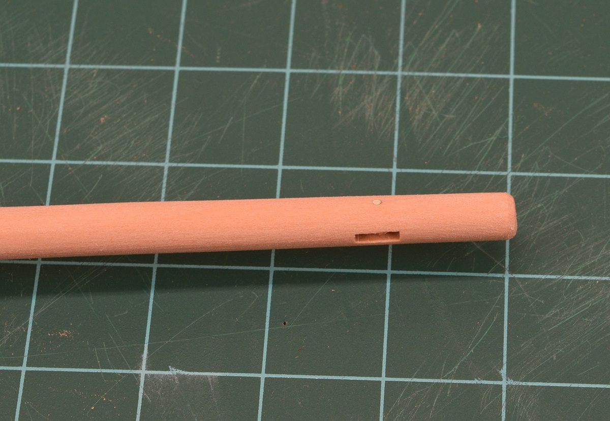
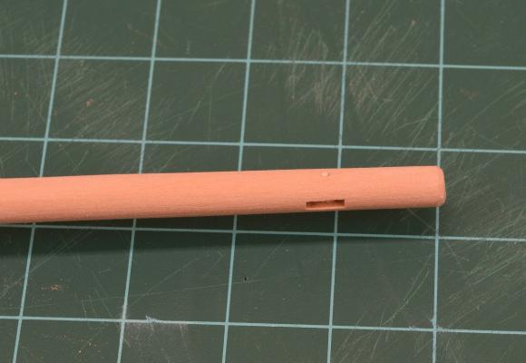 Not super happy with how the one in the jib-boom came out, it's just so small that I had a hard time getting a clean slot cut. I didn't even try to insert a pulley. I'm hoping that with rope run through this it won't look bad.
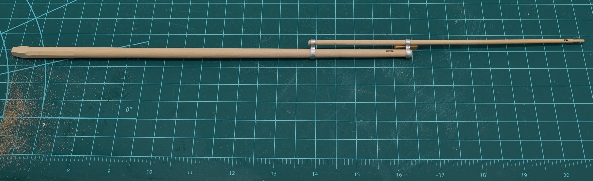
 And here is a shot of the bowsprit and jib-boom together. They aren't actually glued together, I have a bunch of work left to do adding little cleats and stuff to them. Notice the length of this assembly is slightly longer than the length of the hull of the ship it will be attached to!
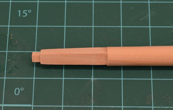
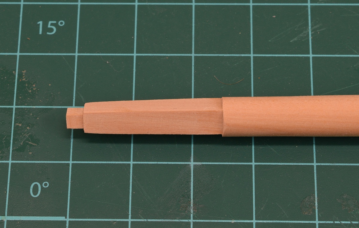
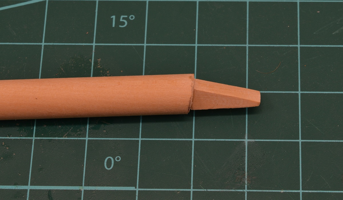
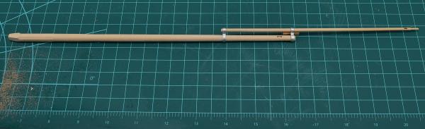 Then I made the main mast. This is the longest piece of wood on the ship, and was somewhat challenging to shape because it was so long. Pictured here next to the remainder of the 1/2" square boxwood that it was carved from. The other pictures are close ups of the top and foot of the mast. Pretty happy that I pretty much nailed the shapes and size on my first go at it. I do have 1 spare piece of boxwood if I had totally messed it up, but glad I shouldn't need to use it.
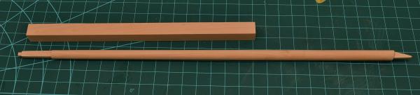

-
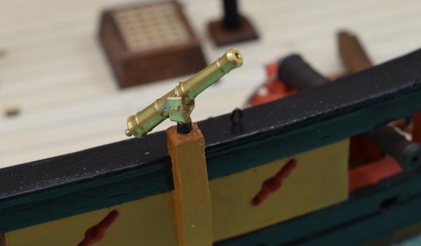
Your canon you are using for your test is pointing at the sky, it doesn't look like you've got the quoin in place, might want to do that before making a final decision on the bulkhead and gunport heights.
-
Neat idea Jerry, and I can see the curve. Nicely done.
-
-
Your drawing looks ok to me, but I've only rigged a single ship so far, and read stuff here and in books, so I'm a far cry from an expert.
No idea what size rope you should be using for what, but in general the running rigging would be untarred (so tan) with only the standing rigging being tarred (dark brown or black).
In theory somewhere in your plans should be a belaying plan, but again, I don't have this model so can't say for sure if it includes one. The Lennarth Petersson book on fore-and-aft rigs has a generic belaying plan for several ship types. If you don't know, a belaying plan is a plan that shows where each line will be belayed to on the deck pin-rails and such. I know that the AVS has this plan included, but my Carmen model did not.
-
Thanks, that clears everything up.
So you would recommend buying Lennarth Petersson's books? Someone has already bought me another model as a gift: the San Juan, also by Artesanía Latina, and the rigging is a bit more complex, maybe a book would be helpful.
I see he has two books, Rigging Period Ship Models, and Rigging Period Fore-and-Aft Craft, what's the difference?
The first book shows the rigging of a square rigged ship, and the second shows rigging of 4 different styles of fore-and-aft rigged ships. Yes, I absolutely recommend them, they are completely full of drawings like the one I posted, in full page format and with each line isolated to show how it works and where it goes.
-
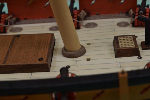
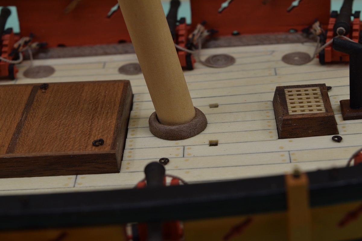
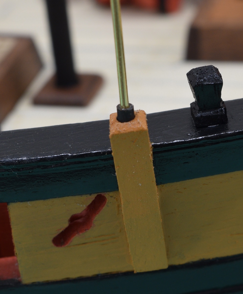
When I added the swivel gun pedestals, I completely forgot to drill the hole for the eventual mounting of the guns, so I needed to do the drilling while already mounted on the ship. I realized that this would be a smart thing to do now, before getting all the rigging in the way, so I had to decide how I was going to mount the guns when the time comes. As I've tossed the cast swivels in the proverbial trash can (I still have them, but am not going to use them), I will need to fabricate new mounts. I played around a bit and figured out what size of brass rod I am going to use, so from there it was a matter of how would I insert them into the pedestals. I chose to try something different, which may allow me to leave the swivels able to actually swivel. I cut off some very short pieces of micro-tube, which the brass rod would barely fit into, and blackened them. I then drilled holes into the top of the pedestals in 3 steps, using small drills, ending with a 1.60 mm bit to allow the blackened tubes to fit.Pretty happy with how they came out, and if I manage to make the mounts for the swivels actually decent (yay I get to practice soldering), I may leave them 'loose' so they can turn. I can always glue them in if I choose also.Here is a pedestal with the tube mounted.
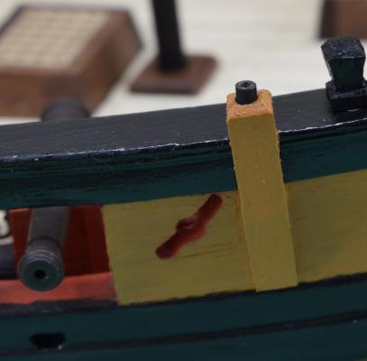 And here is a shot with the brass rod inserted to show how it will fit.
 The yoke for the swivel mount will be attached to the brass rod which will drop into the tube.After that little side project, I went back and began remaking the chain plates. This time I chose to put the 'joint' at the bottom where it can be somewhat covered, or at least disguised a bit, by the nails I was going to use to pin the plates to the hull. They came out reasonably well, although by no means perfect.After initial placement, prior to painting. Way shiny (also this is massively over-exposed to show the plates against the black wale).
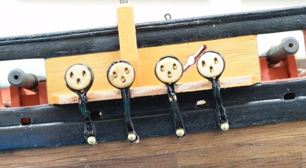 Massively over-exposed shot after putting the cap on the channel and first paint.
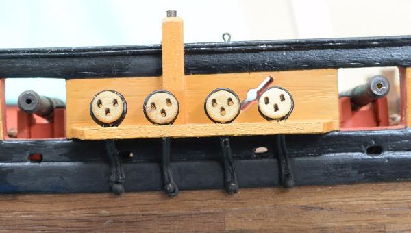 And a only slightly over-exposed shot showing more what the eyeball sees.
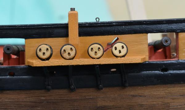 If I was doing this over again, I'd ignore the plan locations and put the holes for the base of the chain plates slightly further up, so that the bottoms of the chain plates wouldn't hang below the wale and make it harder to disguise my bad joint.In any case. The starboard side is done!
- Dubz, Canute, Dimitris71 and 17 others
-
20
-
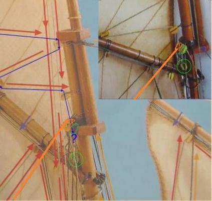
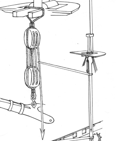
The line highlighted in blue should go all the way to a belaying point at the base of the mast.
The block circled in green is part of the tackle to support the foot of the boom (throat halliard), and attaches to the pulley directly above it. If you look carefully in the inset photo, you will see that there are actually two blocks next to each other above it, one of them is the one this one attaches to, and the other (probably a single block) is taking a rope from the lower left which is probably belayed to the deck also.
I've tried to highlight the green 'pair' of pulleys here, as well as the second one, and it's rope, in orange.
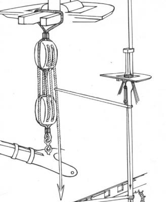
Here is a drawing of the Throat Halliard - credit to Lennarth Petersson. Anyone that is rigging ships should really buy both of his books, they are fantastic.
-
have almost completed the ladies saloon and the lights have been added. I have taken several pictures of the construction up to this point, but forgot to set my camera to a low file size and the pictures came out to big to include in the post.
Looking good.
You can easily re-size your large photo's to fit. If you are using a Windows PC, simply open up the photo's in the included "Paint" program, and in the upper left portion of the 'home' tab tool bar at the top you'll see a 'resize' option. Click that and a pop-up menu will open. Click on the radio-button next to "Pixels", and simply change the larger of the Horizontal / Vertical numbers to 1200. Click Ok, click save. You now have a 1200x on the long side photo that you can use on the forum. Make a copy first if you want to keep the original large photo.
I'm sure there is something similar on Mac, but I don't know what it would be called.
-
I feel you on the sails Bob, that's why I didn't add them to my Carmen.
The windows look fantastic to me, if they don't meet your quality requirements, then your 'acceptable' ones should be marvelous.
- thomaslambo, Canute and mattsayers148
-
3


USN Picket Boat #1 by jct - FINISHED - Model Shipways - 1/24 scale
in - Kit build logs for subjects built from 1851 - 1900
Posted
Looks like you've got a good start. I really like the looks of this kit, and it's on my radar for 'some day'.