ccoyle
-
Posts
10,594 -
Joined
-
Last visited
Content Type
Profiles
Forums
Gallery
Events
Everything posted by ccoyle
-
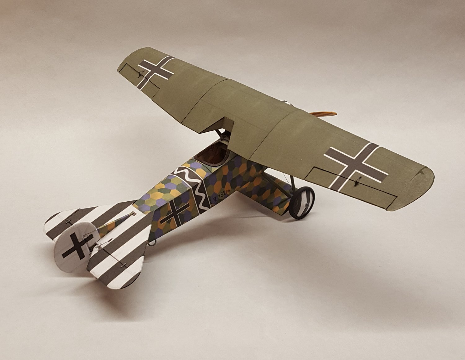
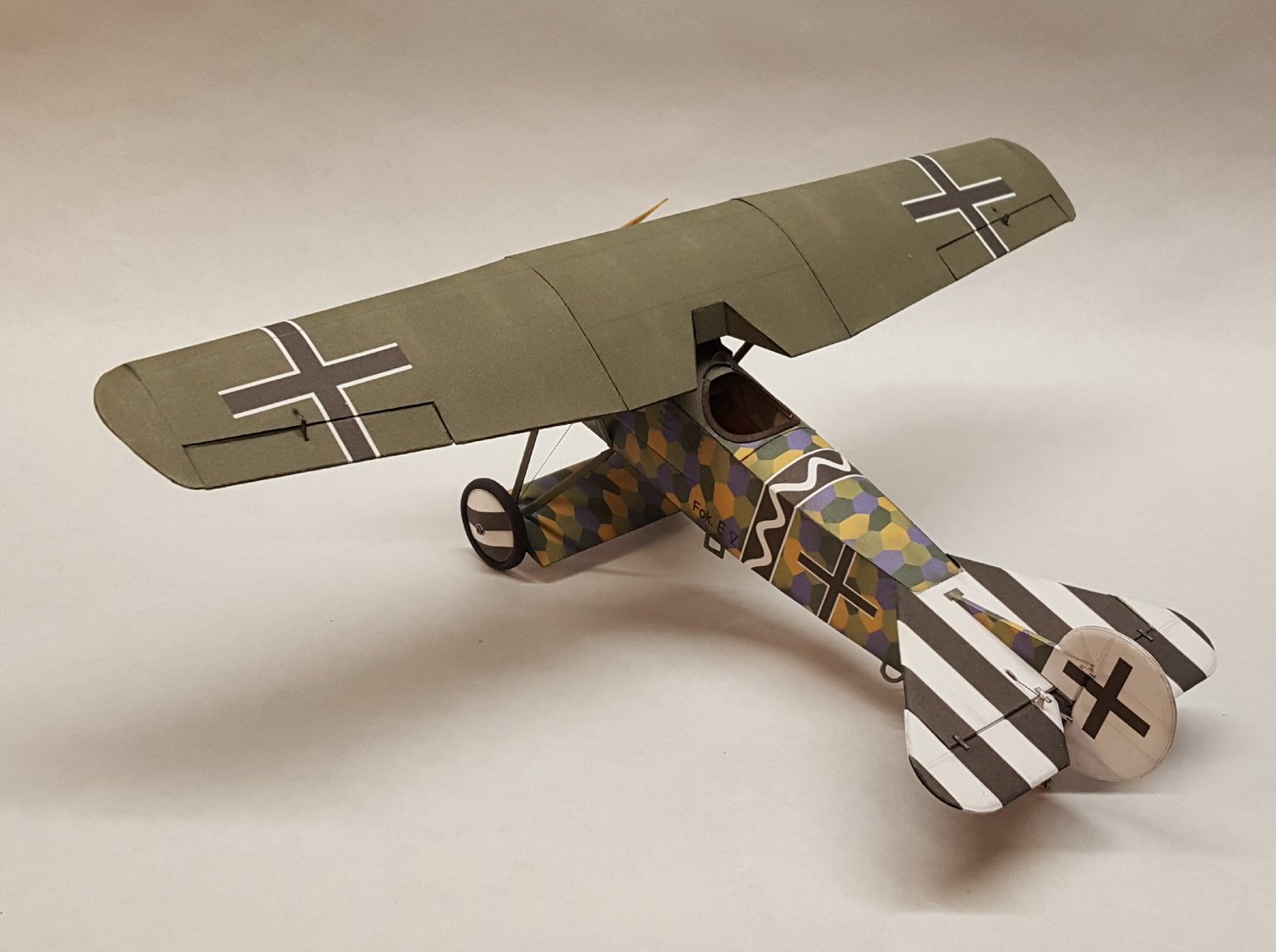
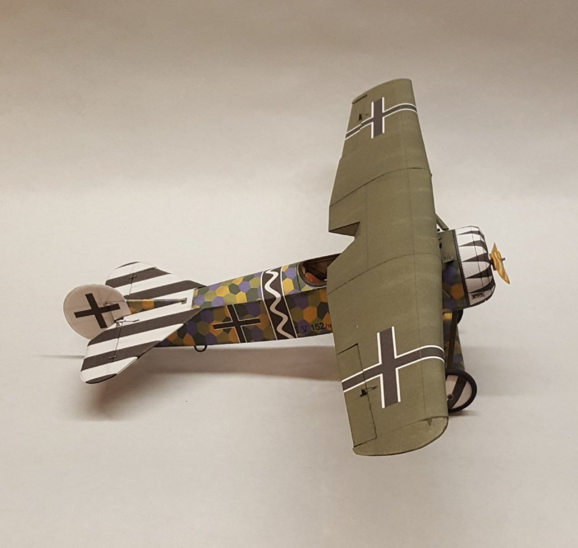
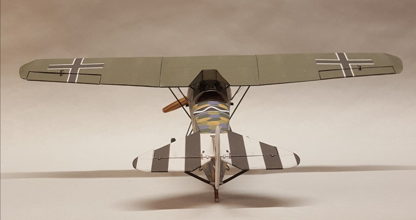
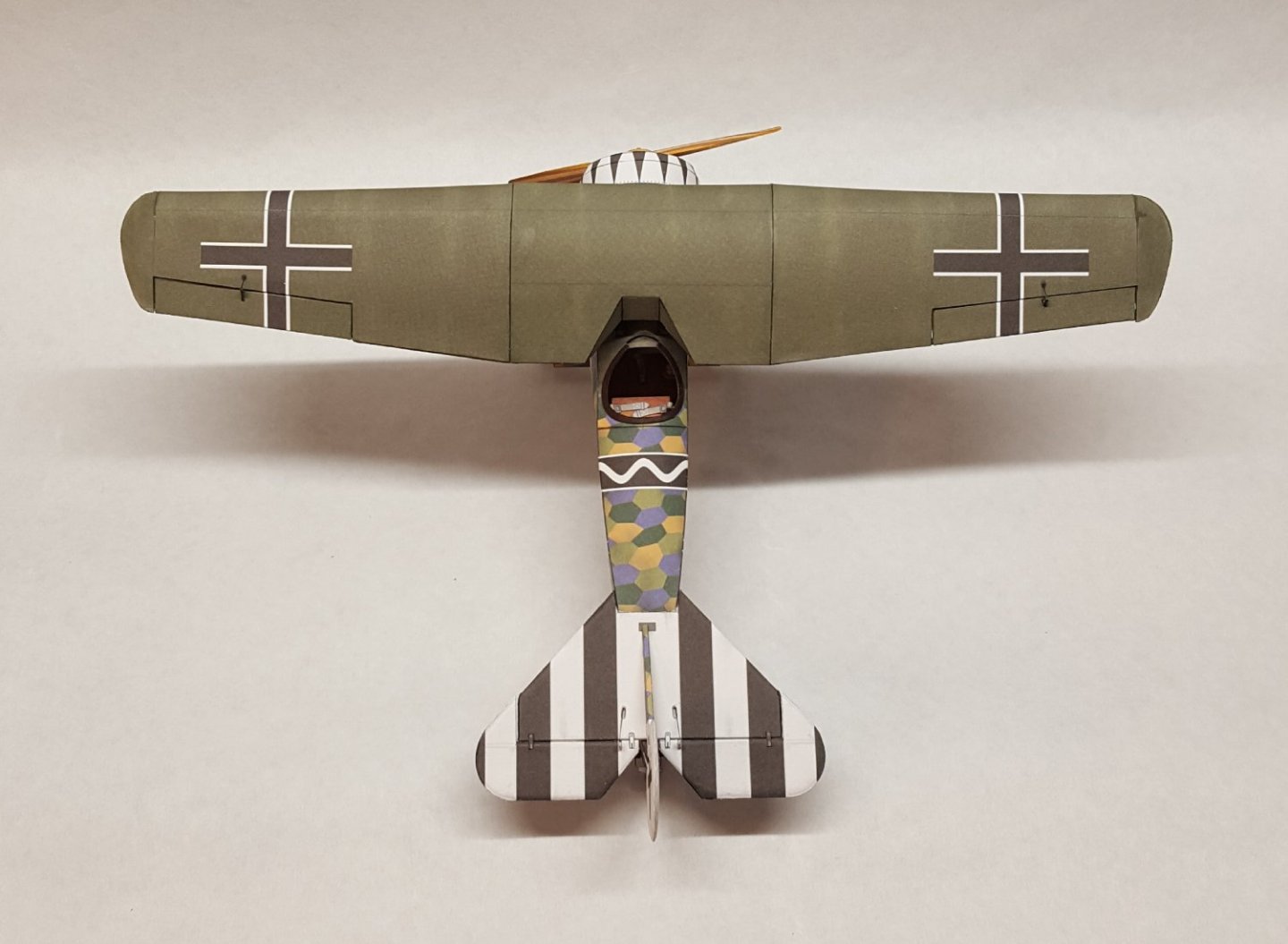
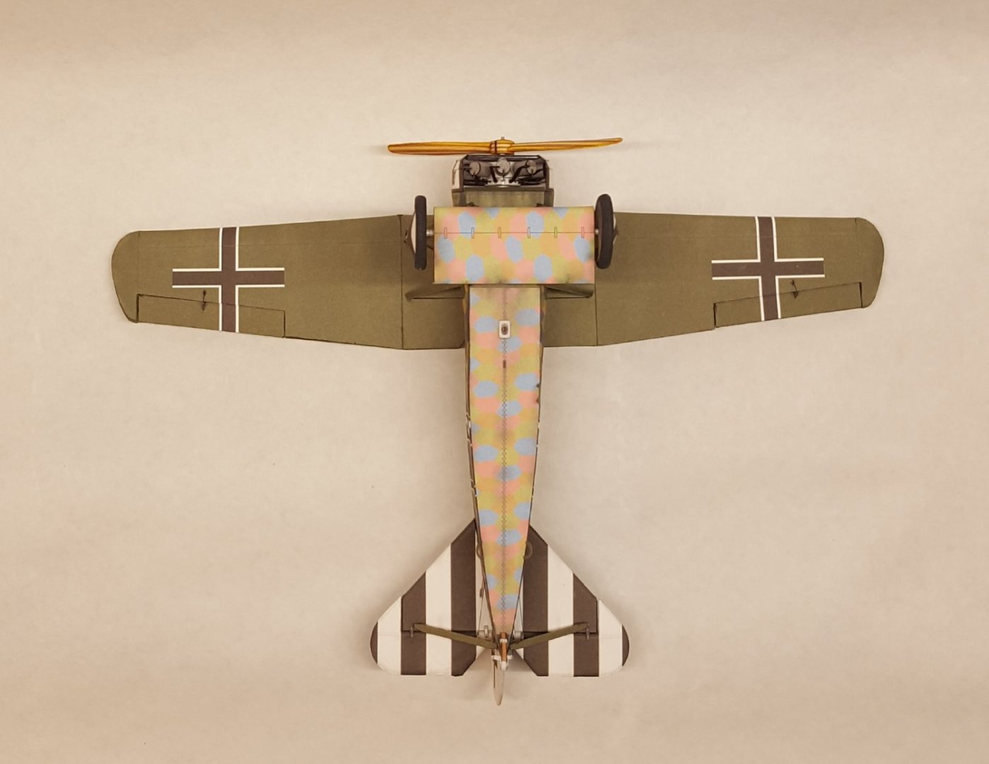
 The Big Reveal! Yes, three weeks to the day and she's finished - another fantastic model from Kartonowa Kolekcja. I can't say enough good things about Pawel's designs -- they very nearly fall together by themselves. Anyways, on to the pictures! I noticed as I was posting this next shot that the entry step got knocked askew -- gonna have to fix that. Thanks to everyone who has followed along, liked, and commented. I hope you have enjoyed this quick build, and we'll see you on whatever is next!
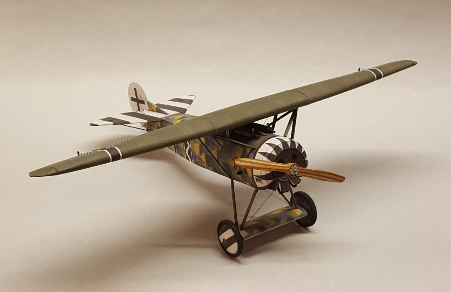
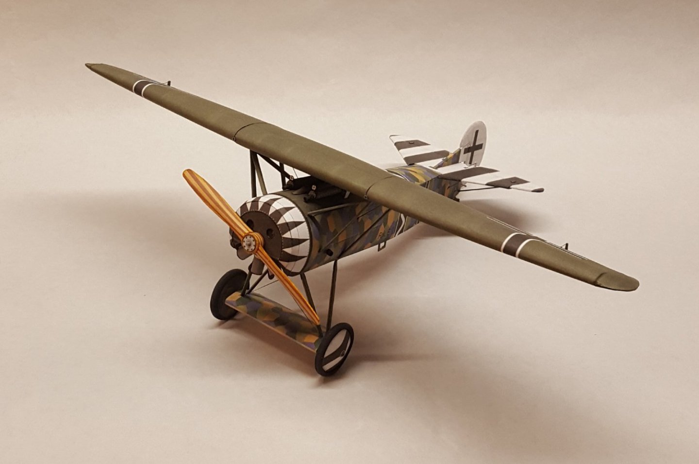


- 46 replies
-
- 28
-

-

-
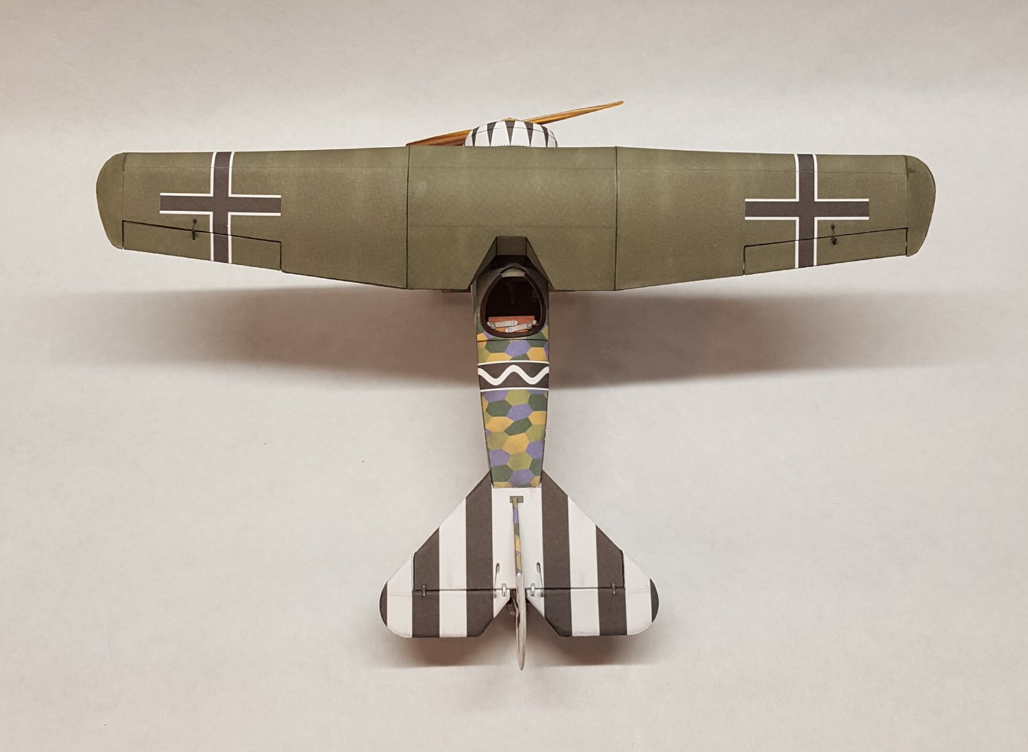
Empennage under way. Hard to get any work done with so many World Cup games to watch. 😆
- 46 replies
-
- 14
-
-
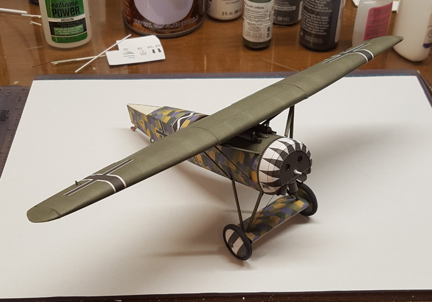
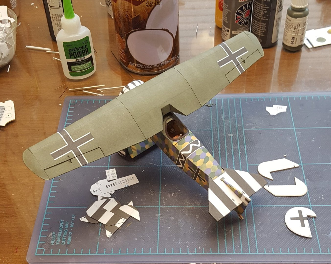
Moving quickly along . . . The wing was finished off by the addition of ailerons and control horns with their cables. Struts were made by wrapping the paper parts around 0.020" steel rod, then glued to the fuselage. Finally, the wing was mounted, bringing the model to its present state. For future reference, I should note that some of the struts, both for wings and for undercarriage, appear to have been misnumbered when compared to the diagrams, but a careful study of the diagrams reveals their correct placement on the model. Cheers!

- 46 replies
-
- 17
-
-
I built one, too. Mine connected with a mailbox on its very first flight. 😬
-
First question is, does your kit include a sail plan? It's not 100% necessary, but takes the guesswork out of making sails with the proper dimensions. Making your own is not terribly difficult, especially if you glue them instead of sewing them (my preference).
-
I have probably seen pictures of it. I didn't realize that the Old Rheinbeck Aerodrome was in New York -- I just assumed it was in Europe somewhere. 😬 I've never been to New York. 😬😬
- 46 replies
-
- 10
-
-
Welcome aboard! Dedicated shrimpers are rare in kit form, as are modern workboats in general, at least if you are looking for US examples. Several kits for European/UK boats do exist, though these tend to portray older, sort of 'classic' boats. What kind of vessel did you have in mind?
-
Slipping in from Massachusetts and Minnesota
ccoyle replied to Janelle's topic in New member Introductions
Garlic and apples -- an interesting combination. Welcome aboard! -
Aha, another cardist (see signature)! Welcome aboard!
-
That's a very handsome model, Jeff. Well done!
- 23 replies
-
- 1
-

-
- Herreshoff 12 1/2
- BlueJacket Shipcrafters
- (and 1 more)
-
Please be advised that the plans produced by that "Japanese guy" constitute an unlicensed reproduction that he is not legally entitled to distribute and thus violate our site's intellectual property rules. I'm not familiar with the other set you mention, but the same rules apply if his work is an exact BP likeness.
-
The plans should be available from BlueJacket Shipcrafters, since they make a kit of the Notman.
-
You can send Kurt a private message here in the forum. His username is kurtvd19.
-
Hi. Sorry to hear about your husband. I have removed your email address to protect you from spam bots. Interested members may contact you by private message. To ensure that this is a genuine offer, please post some photos and descriptions of your husband's materials. Also, you might be interested in donating the materials to a local club. It's a not-uncommon practice, and clubs typically auction off the donations to raise funds. There is a local club that meets in Portland -- you can find their contact information by clicking this link, then scrolling down to the Oregon clubs. Kind regards, Chris
- 1 reply
-
- 2
-
-
The tackles on the 1/64 scale 4-pounders for my Sherbourne required 2 mm blocks -- they were tiny, and definitely a challenge to work with.
-
You may post it in the new member introduction area. Say a bit about yourself and how you came to be in possession of the model, along with some pictures (the more the better for identification purposes).
-
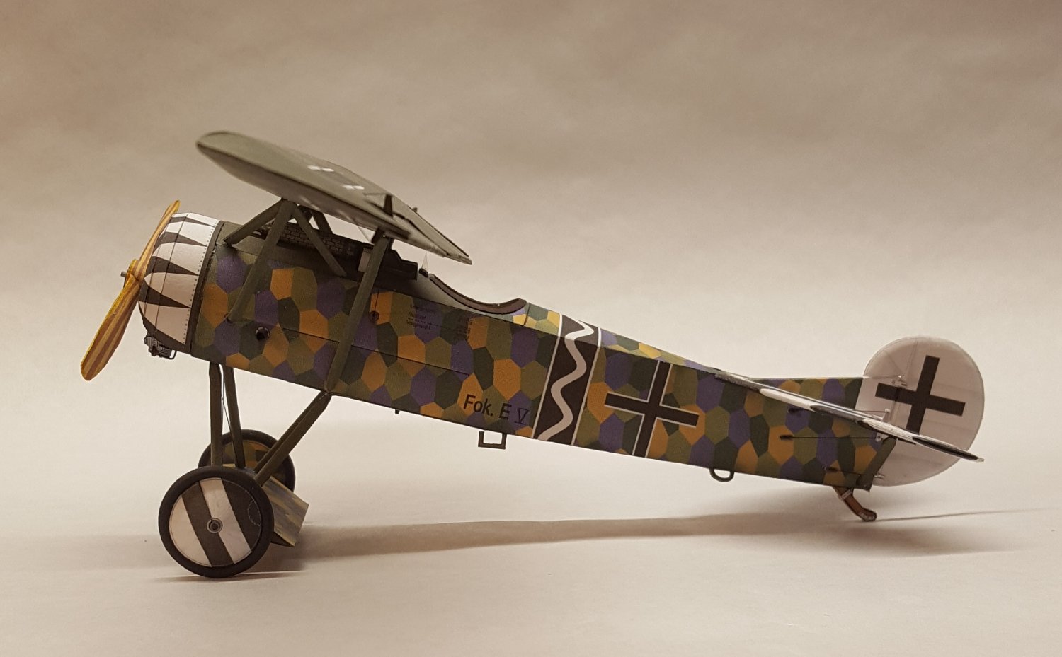
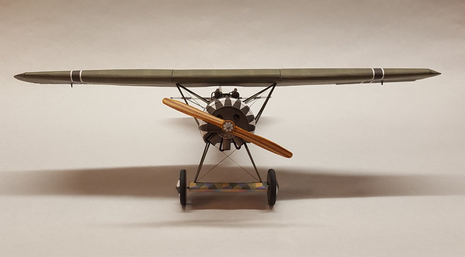
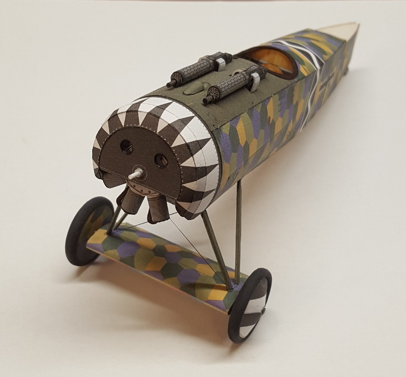
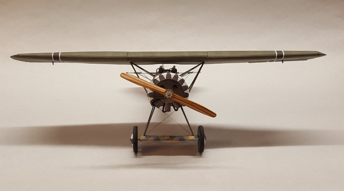
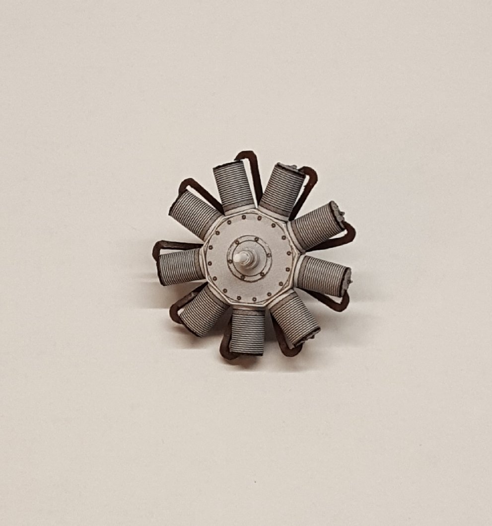
Oberursel UR.II engine. The E.V was actually designed to take a more powerful engine, but the new powerplant was not available in time for production, so the older UR.II was used. Still, the E.V was light enough that the older engine was able to produce a top speed of 127 mph.
- 46 replies
-
- 17
-
-
Who? Me?? 😳
-
I agree. It's quite striking!
-
I don't know why, but I'd always assumed that you were much younger than I. You are younger, but not that much!