DONATION DRIVE - SUPPORT MSW - DO YOUR PART TO KEEP THIS GREAT FORUM GOING!
×


ccoyle
-
Posts
10,520 -
Joined
-
Last visited
Content Type
Profiles
Forums
Gallery
Events
Everything posted by ccoyle
-

Bristol Beaufort by AJohnson - FINISHED - Airfix - 1:72
ccoyle replied to AJohnson's topic in Non-ship/categorised builds
Nice work, Andrew! -
I will answer those questions for you, since I'm the one who moved your topic. As you admitted, it is not a ship model, so the build log sections were not the right place. I admit that I wrestled with where to move your project -- it's one of those projects we get from time to time that doesn't fit neatly into one of our established sub-forums. It then becomes a judgment call about where to place it. If I'd left it in the build logs area, I'm sure some members would have wondered why a non-model was in that area. You can see the dilemma. The reason why we have that non-ship sub-forum "at all" is because members asked for it, and as you can see it is a popular feature at our forum. And your build log is no more "buried" in that area than in any other part of our site. I use the "all unread content since my last visit" feature and your topic came right up. The reason why I marked your project as finished is because it did appear to be finished, and it is not uncommon for members to not mark their projects finished when they are done with them. Again, it's a judgment call.
-
I love the Buffalo! I built a 1/72 scale kit as a kid, have the finished Kartonowa Kolekcja version in my display case, boogered the Halinski version (Finnish aircraft), and have a replacement Halinski kit in my stash.
-
Oh, Mike, Mike, Mike . . . if I were to share more of the work of the True Masters of this medium (a group that does not yet include me), we'd all quit and take up knitting. 😂 Anyways, I have hung the rudder. I canted it a bit to starboard -- that creates the visual illusion that the vertical stabilizer isn't quite so crooked.

- 165 replies
-
- 16
-

-
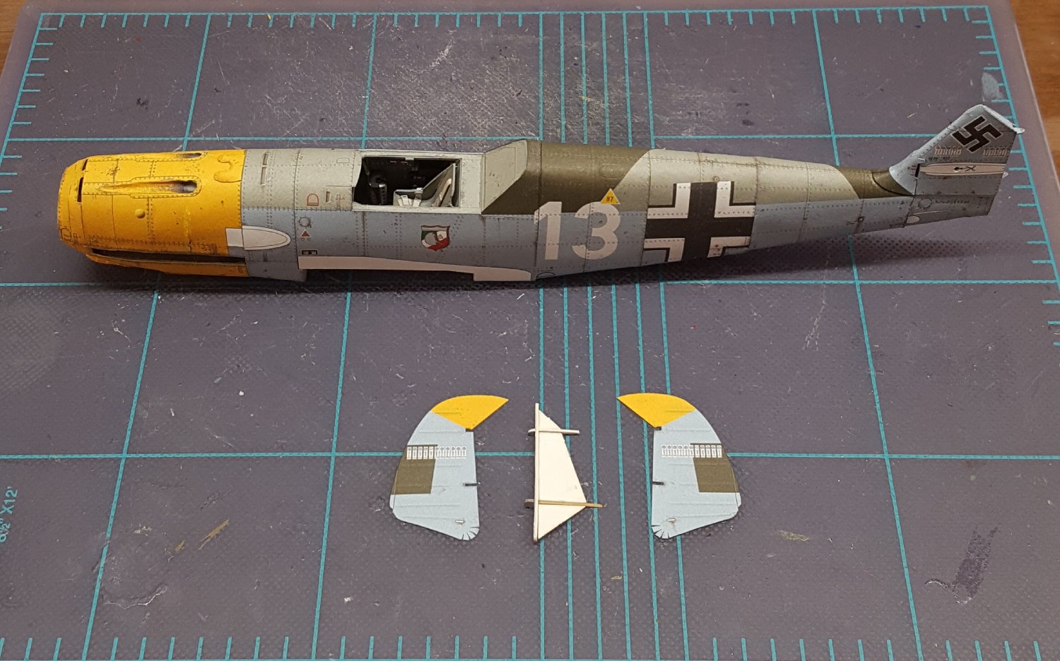
The vertical stabilizer has been added. It has a substantial amount of substructure, as can also be seen for the rudder. Unhappily for me, the stabilizer is noticeably crooked -- a fact I failed to notice until after the glue had well and truly set. This will subsequently require the judicious use of flattering camera angles.

- 165 replies
-
- 18
-
-
Shoot a pm to MSW member greenstone. He works for the company.
-
Hi, Dan. For the kit, there is a section for general kit discussions. For parts, use the tips & techniques section. There is a section for painting as well. Most of what you need to ask you can probably ask within your build log, should you choose to start one. Cheers!
-
Parts are dampened first and then carefully formed over a variety of tools -- whatever has the right shape and diameter. Nope. I always have to be careful afterwards about where my forgetful fingers grip the thing.
- 165 replies
-
- 11
-

-
-
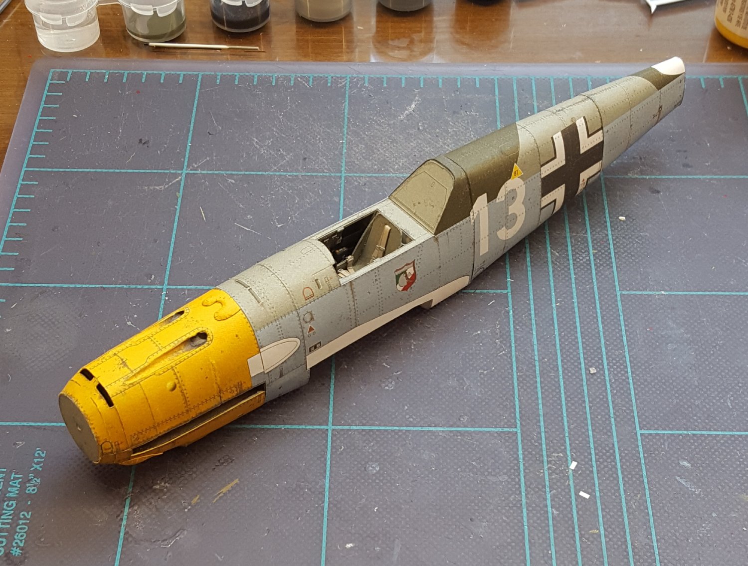
Various covers in place -- it was hard to find an angle that showed all of them. And a standoff view . . . Next up is constructing the aft fuselage.
- 165 replies
-
- 15
-
-

-
Nice work, Nils! Pilot schooners make handsome projects.
- 180 replies
-
- 3
-
-
- pilot boat
- Elbe 5
- (and 3 more)
-
I always use a fresh #11 blade for the task. I do the job freehand, and I don't try to cut all the way through the card on the first pass -- score the cut first, then cut through on the second pass. On the curved section I use a jigsaw-like motion using only the tip of the blade and pushing the blade forward instead of drawing it back. I should add that although I have been using the Evergreen Canopy Glue for most of this build, I did not use it for seating the channels, since that task requires more working time to get everything seated properly. I used Aleen's Clear for the job.
- 165 replies
-
- 12
-
-
-
Very nice -- congratulations!
-
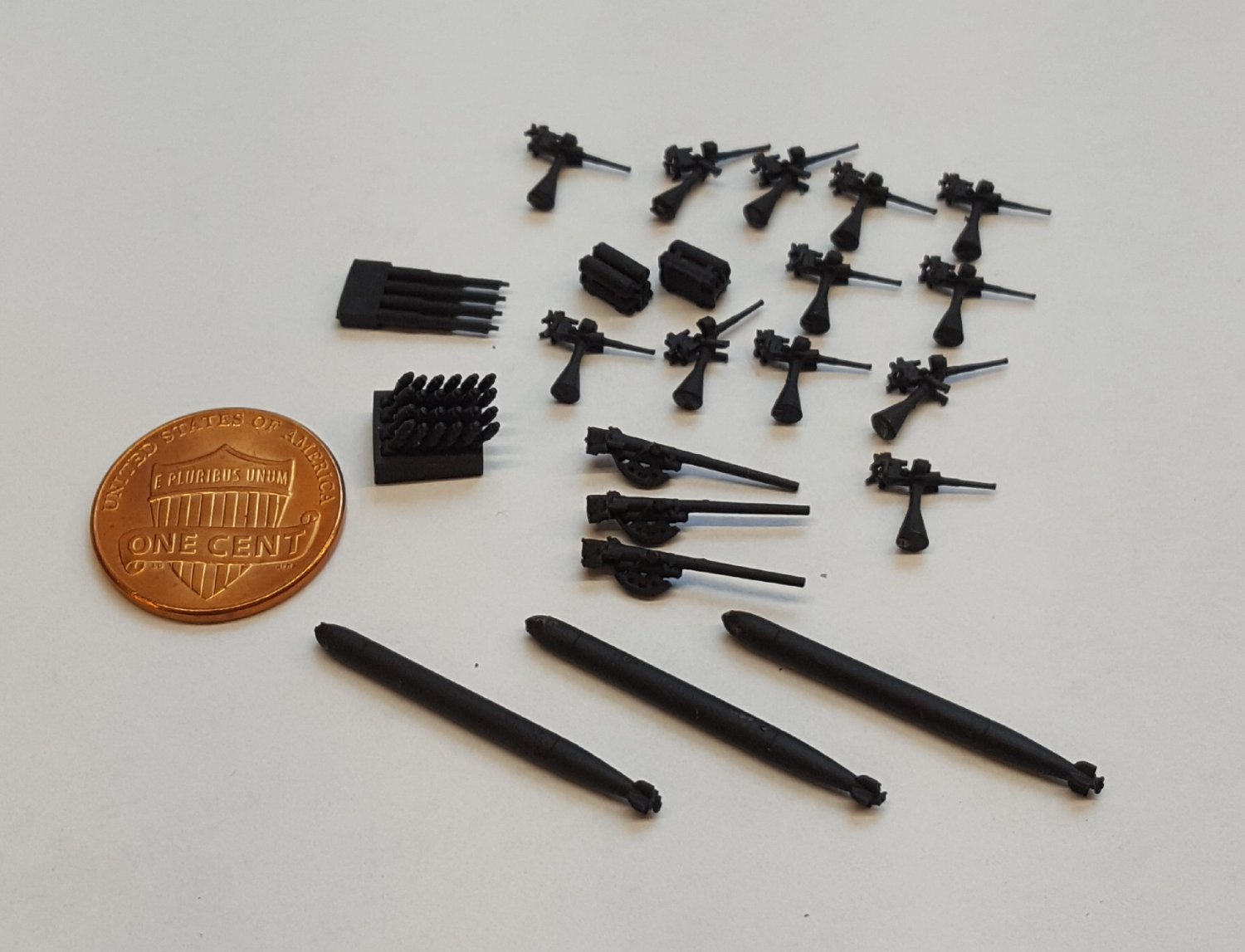
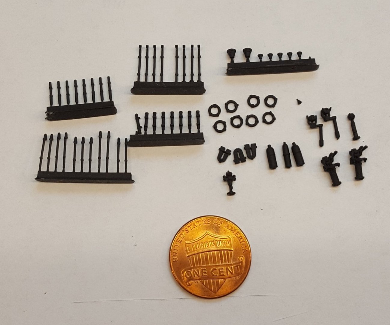
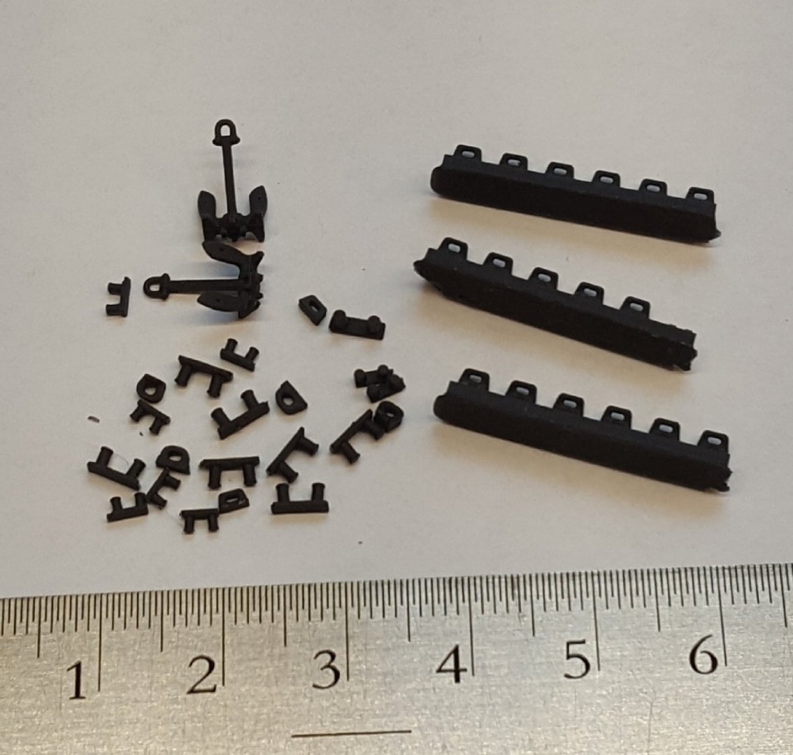
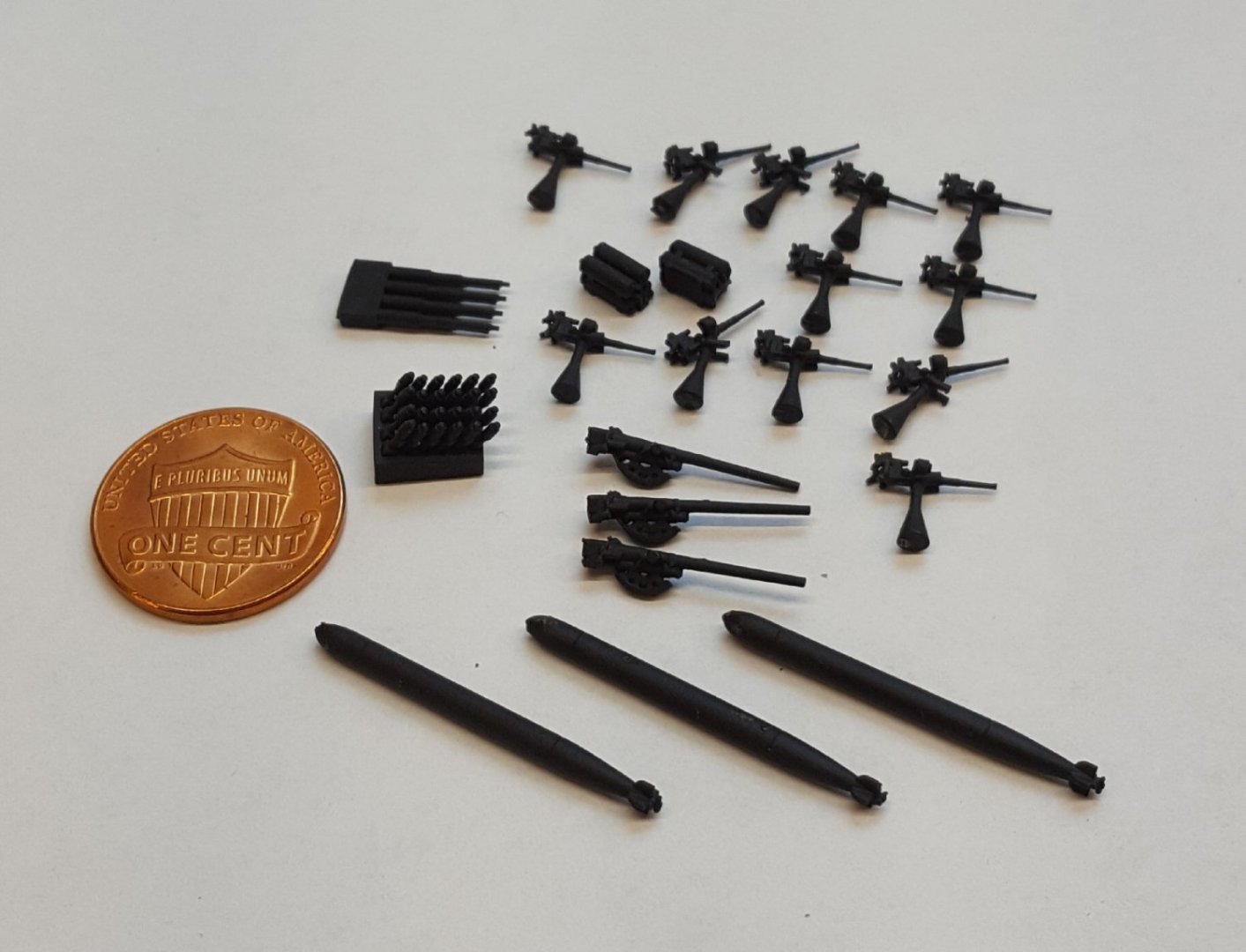
Some goodies arrived in the mail today. These are 3D-printed detail parts from Darius Lipinski, the kit's designer. I have already added the paper versions of some of these parts to the model, but the printed parts are so nice that I might just be tempted to see if I can safely remove some of those paper parts and replace them. So, what have we got? Vents, valves, life rings, hoses, binnacle, signaling lamps, directors. Anchors, bitts, fairleads. And finally, armament: 20 mm mounts, barrels for 3" and 1.1" guns, torpedoes, and hedgehog bombs. This build will probably go back on the bench after I complete the 109 build.
- 331 replies
-
- 20
-
-
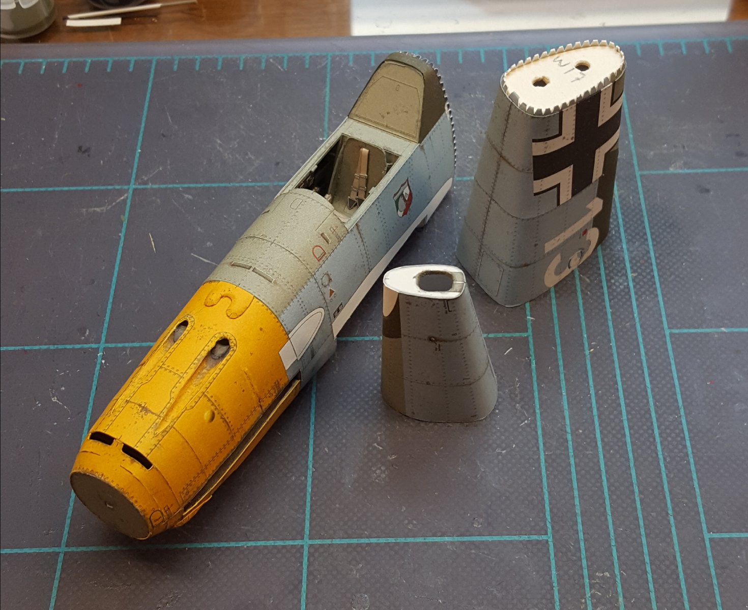
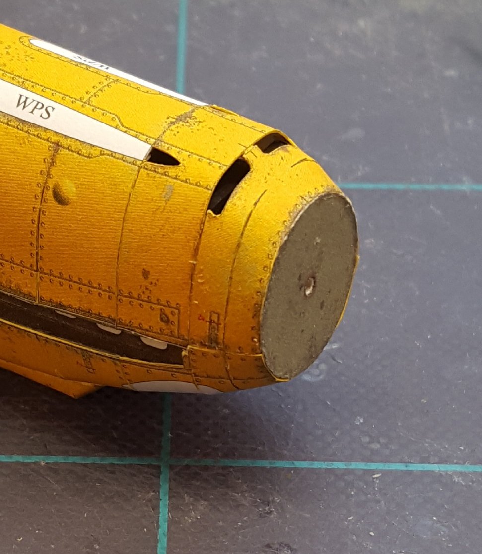
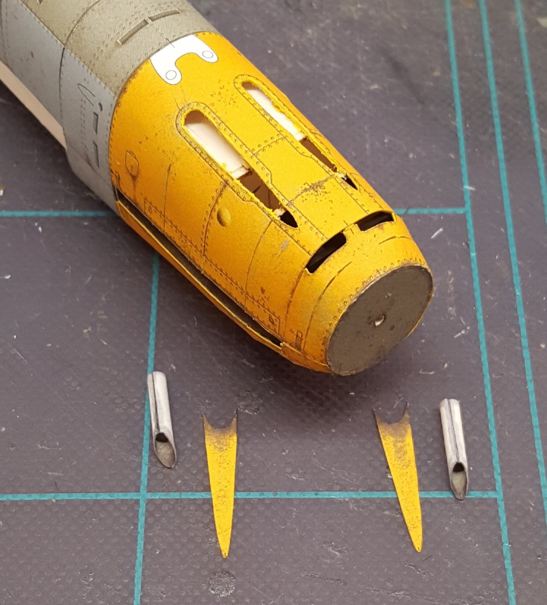
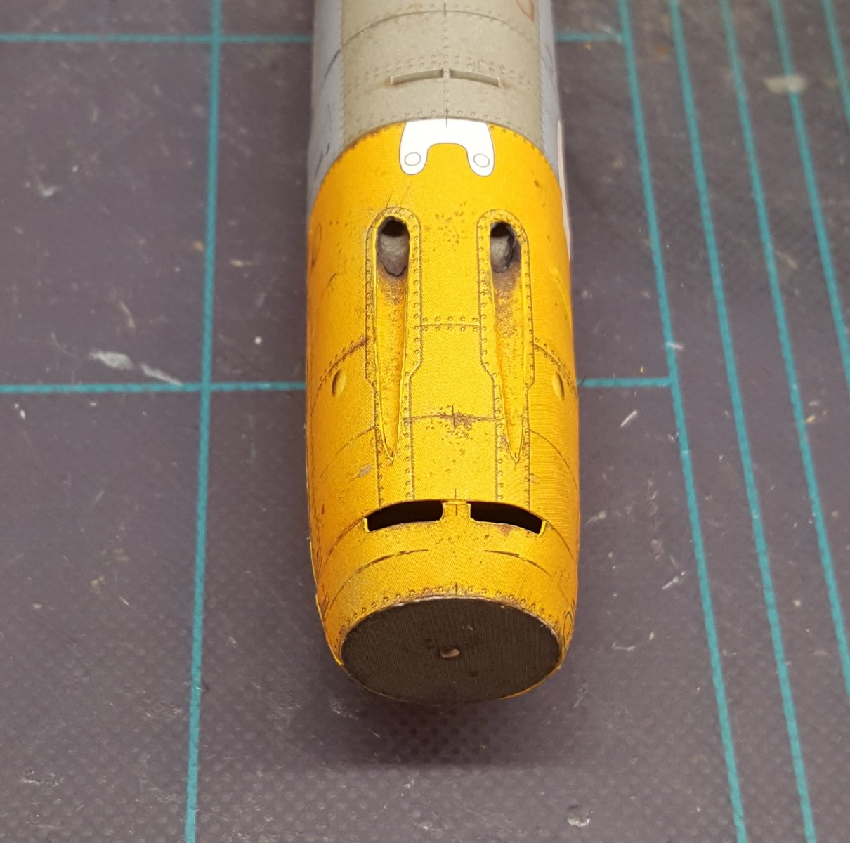
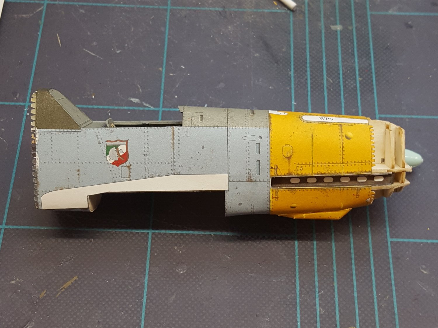
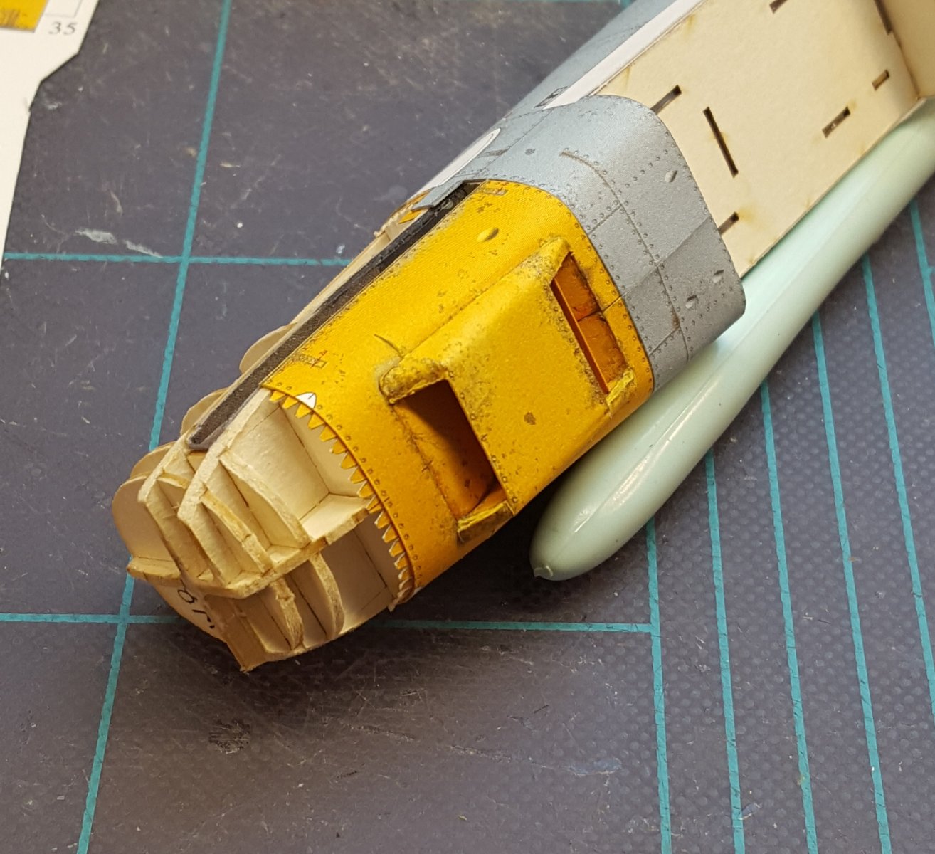
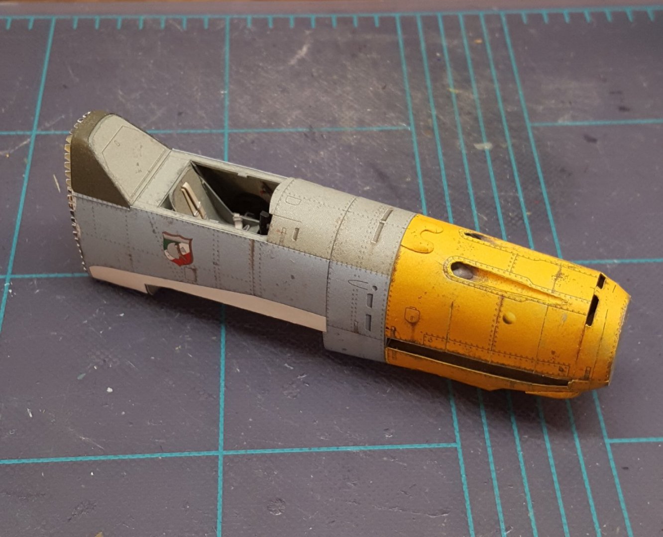
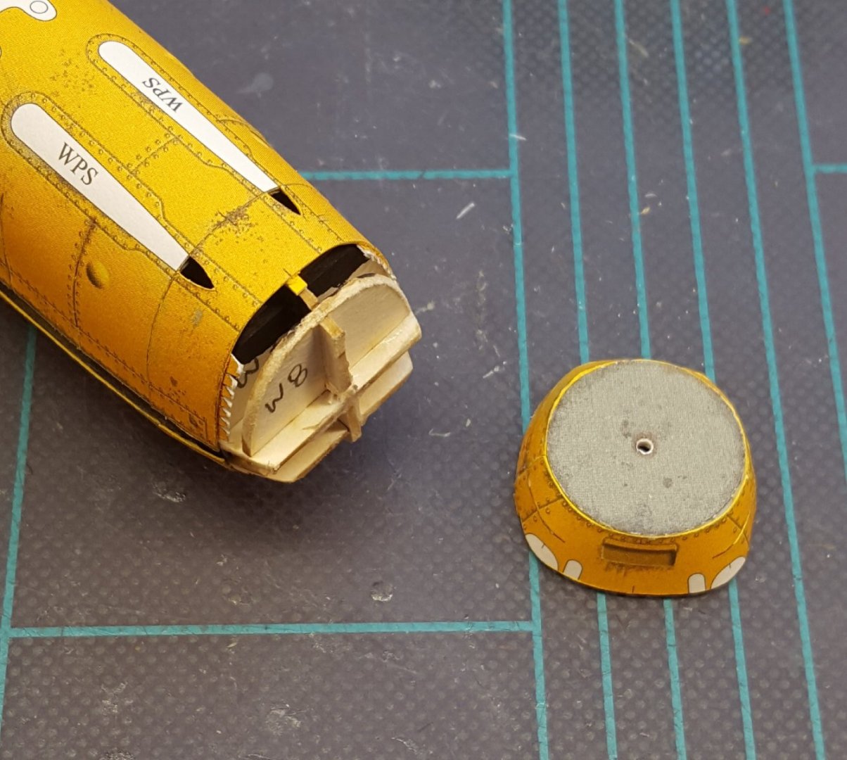
Further progress: First the penultimate nose skin was added to the fuselage. The last skin consisted of two pieces, which I chose to join together first before adding them to the fuselage. The last frame was also added to this piece. Then that structure was added to the fuselage. The fit so far has been no problem. The letters WPS indicate sections that are to be cut out after the part has been glued. These are of course the machine gun channels. Those portions were duly removed, and the parts for the channels were prepped. And here's the finished channels. That's all for now!


- 165 replies
-
- 17
-
-
-
-
Witam, Wieslaw! I saw your ORP Piorun model in the gallery -- a very high level of craftsmanship. Thanks for sharing!
-
Next we have the oil cooler. It's a tiny bit lopsided, but considering how complex the structure is, I'm happy with it.

- 165 replies
-
- 20
-
-
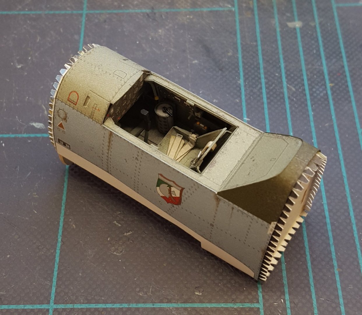
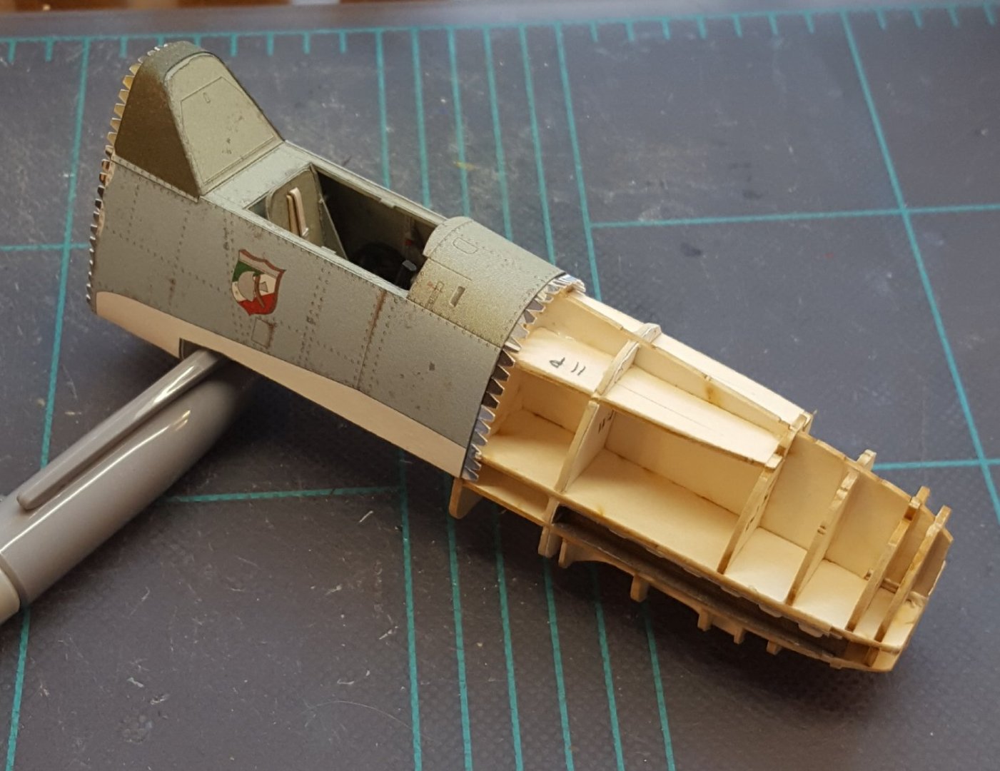
It seems our Chinese friends are a little sensitive about displaying the Nationalist roundel, much like German kits are not allowed to include swastikas.
-
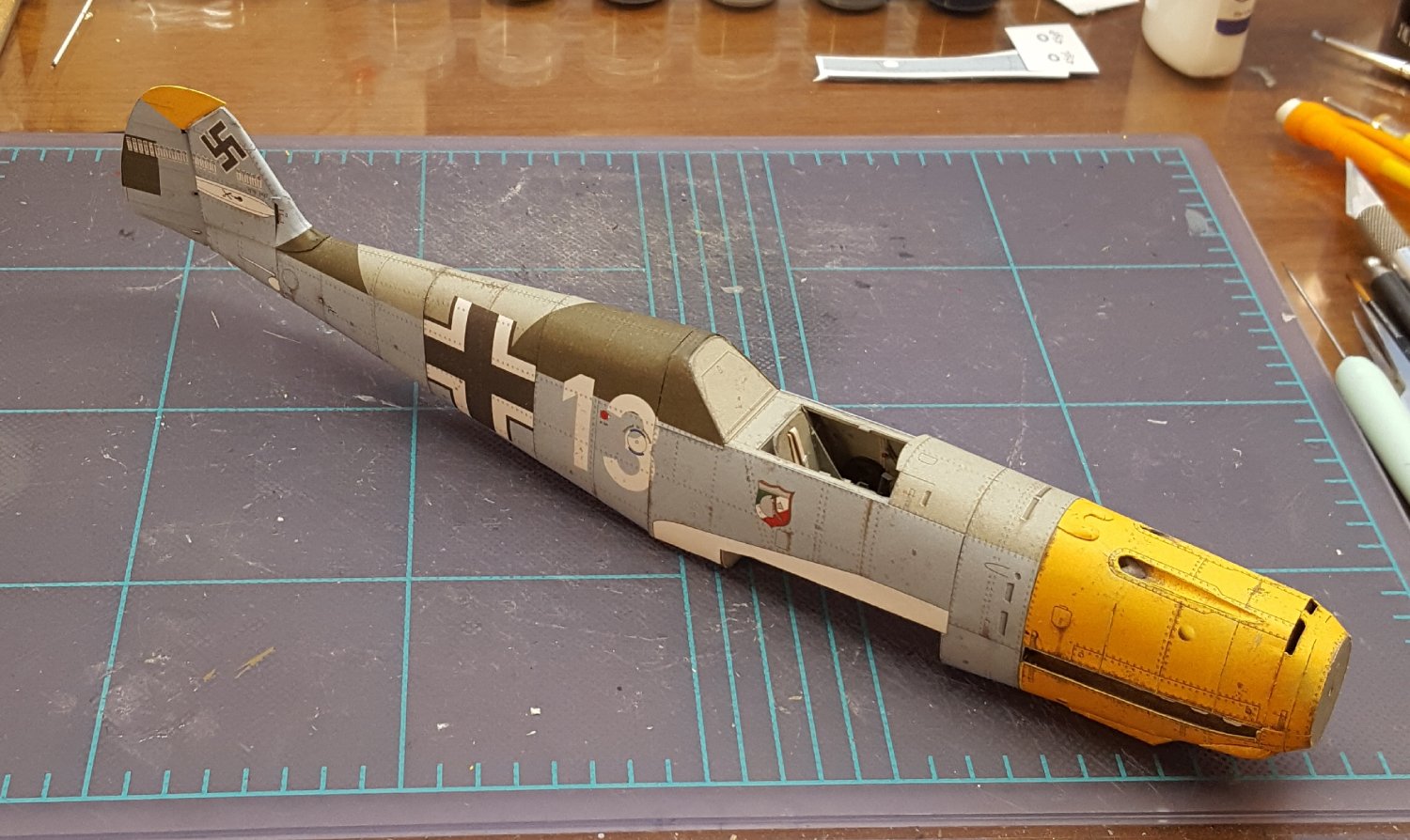
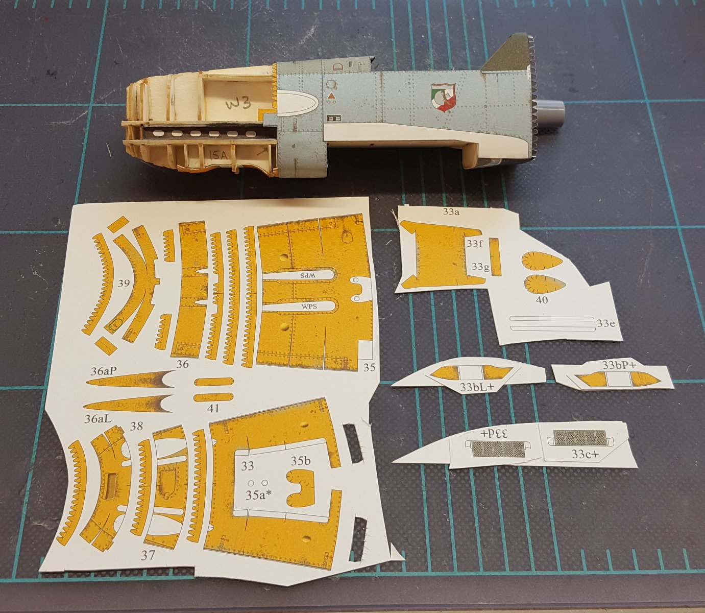
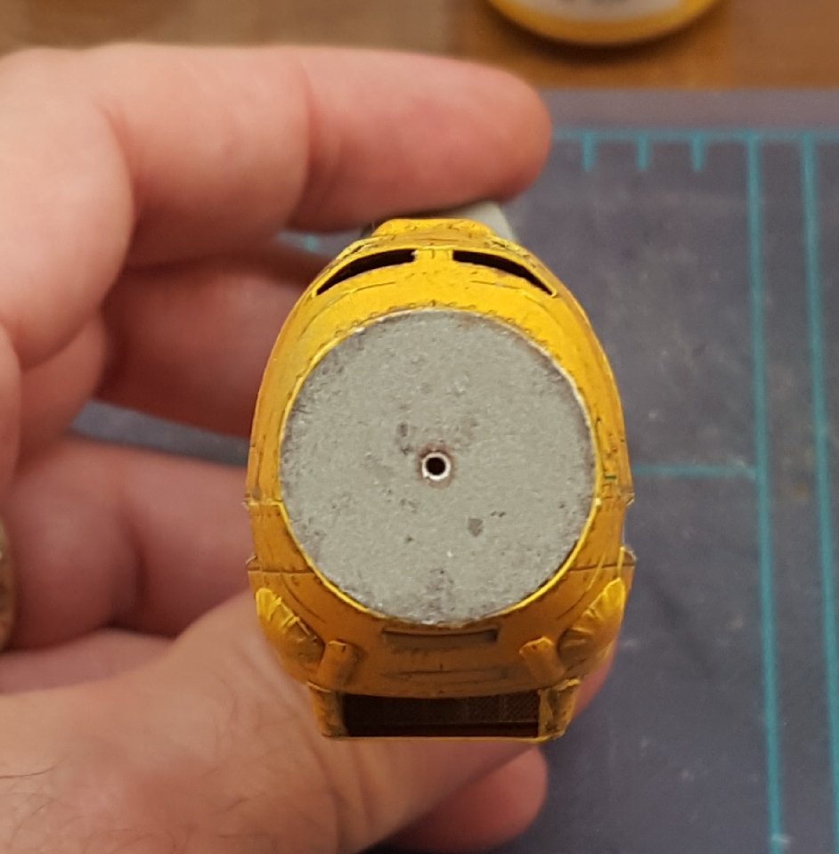
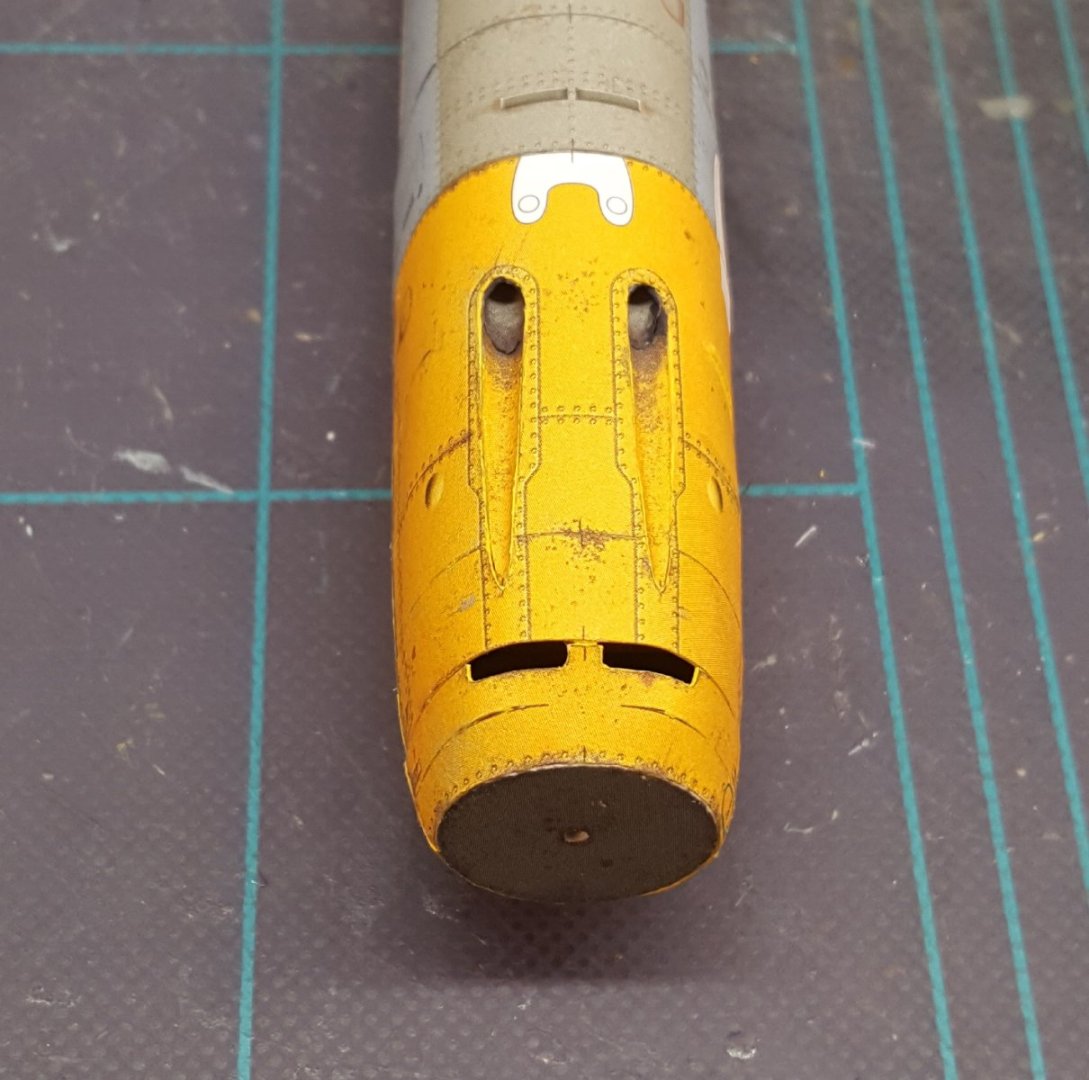
A nice milestone moment in the construction of a plane is getting the first outer skin on. On some Halinski builds, I have had a lot of issues with the inner cockpit skins not fitting correctly -- they must align precisely and have no gaps at the seams, otherwise the outer skins won't fit either. Fortunately, this time around only some light sanding was needing to achieve the desired inner skin fit, and the outer skin thus went on without a hitch. The nose frames were then assembled and mated to the cockpit section. You can see that there is a substantial amount of substructure. After adding one more fuselage skin (it fit perfectly and won't even require any seam touch-ups), it's time to work on the nose. The Emil had a rather lumpy, bumpy nose (a characteristic that was addressed in the 109F), and that is reflected in the jigsaw puzzle-like nose assembly sequence for the model. Patience will be the order of the day!

- 165 replies
-
- 19
-
-
Every time you step out in it, you can shout, "Release the kraken!"
-
Anyone out there working on a card model?
ccoyle replied to gagliano1770's topic in Card and Paper Models
Me, too -- but if I recall correctly, I have to go off-site to see the build log for this one (hint, hint). 🤨😉 -
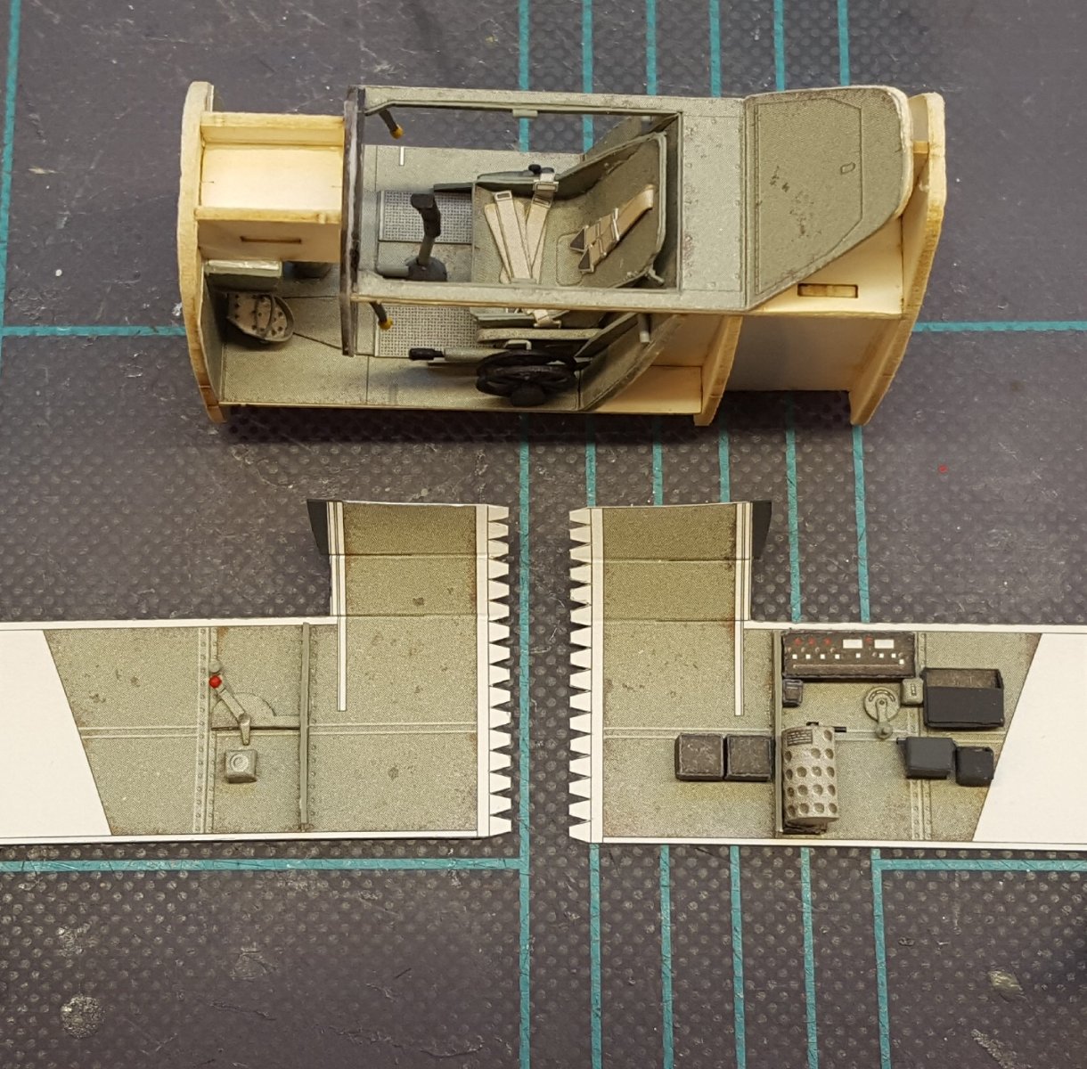
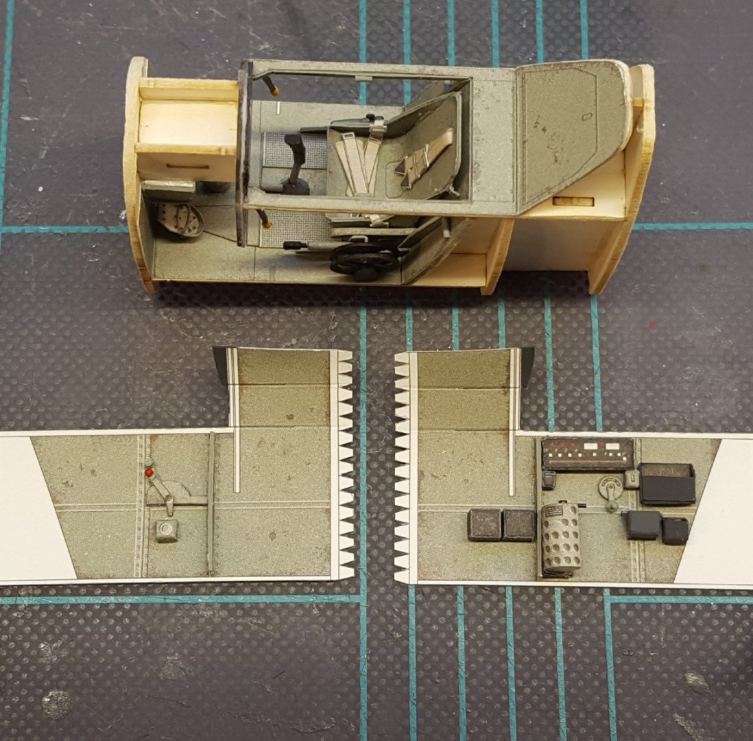
Take a good look -- this is the last time you'll be able to clearly see all of the cockpit elements before everything gets closed up. Port side on the left, starboard on the right. The disparity in the number of controls on the two sides makes me wonder whether the Luftwaffe chose only right-handed pilots for fighter pilot duty. 🤔
- 165 replies
-
- 15
-