HOLIDAY DONATION DRIVE - SUPPORT MSW - DO YOUR PART TO KEEP THIS GREAT FORUM GOING!
×


Landrotten Highlander
-
Posts
269 -
Joined
-
Last visited
Content Type
Profiles
Forums
Gallery
Events
Everything posted by Landrotten Highlander
-
I love to take part. Does the fact I live in the UK pose any issues (i.e. additional cost / delay in obtaining materials, etc)? Slainte gu mhath L.H.
-
Gondola by AntonyUK
Landrotten Highlander replied to AntonyUK's topic in - Build logs for subjects built 1901 - Present Day
looks interesting, will be following -
I am involved with the building of the HMS Victory (a memory to the owner's father). When researching the copper plates I found that the fitting patter is overlapping top/bottem, as well as side to side. Another detail is that unlike a brick wall (where individual brick rest equally on 2 underlying bricks) with copper plates the overlap is 1/3 vs 2/3 - i.e. on one tile the overlap to the lower row is 1/3rd of the tyle, on the adjacent (lower row) tyle it is 2/3rd. I have been told that pictures of the ship are on facebook group Library North Ayrshire, Scotland. Hope this info is of use to you. L.H.
- 14 replies
-
- 3
-

-
- pickle
- caldercraft
- (and 1 more)
-
I am in awe and inspired by your determination to make beautiful models with the limited tools you have. Reminds me of the whittled wood or bone ships I have seen in the Edinburgh Castle museum. Those prisoners did wonderful things and the only tool available to them was their knife. Keep up the good work Slainte, L.H.
-
I think it refers to 'knife + finger =expletive of yout choice'
-
I do not think we can simply translate modern thinking to that of earlier periods. I believe that the embelishments on ships (and buildings) was the only way to suggest wealth (and thus power). Look at the British admerality shipbuilding guides: it took nearly a century for both the goverment and the ship buillders to drop the (unnecessary) decoration - or have it replaced by a cheaper form. The merchant fleet has always been different to any naval fleet, since the merchants had to pay for eerything, so anything that does not lead to profit (directle or indirectly) had to go. I personally think this is a very valid interpretation. Slainte L.H.
-
I think the danger does exist. Mind you, I never tried the tape in combination with superglue, but that sort of stuff is used in many industries....
-
take a sowing needle. Cut the eye in half so you end up with a u-shape. use this to pick up some Iliquid) superglue (caterpillar capilliary action). carefully line up both pieces and let the caterpillar do its work from above. use little glue, then quickly spray with activator = instant bonding. edit: perhaps place first on surface that does not glue well (teflon sheet, https://www.ebay.co.uk/itm/1pcs-10mm-x-10m-PTFE-Teflon-Adhesive-Tape-Nonstick-Sealing-Machine-Tape/302526316786?epid=546897656&hash=item466ff940f2:g:rSMAAOSwO7haCVlp, perhaps)
-
Just found your log as I am considering building a Bismark or Tirpitz in 1:350. Done a b****y good job of it, and I particularly learned about adding PE from your build. Re the Tamiya Flat Silver problem, I found it never looks right, as the flakes in the paint are waaaaayyyyy too big. Humbrol/heller paint is a much better option - and should be easy enough to find. Having said that, I also paint scale figures, and I have found Jo Sonja silver (acrylic) to have no equal regarding flake size, it is just one smooth surface wathever the scale - and even use it for highlighting bare metal. Unfortunately this paint is not so easy to find . If you are up to it (and think the extra effort is worth it) then you could very easily paint over the Tamiya silver using a brush. Apart from the Jo Sonja, I dilute my paint to a milky consistency (or even a bit more watery), and prefer to apply several thin 'washes' works better than trying to cover with a single layer of paint. I will keep following you log from now on. Slainte, Landrotten Highlander
-
I think I can add a few reassurances as well as tips. When I paint miniature figures (be it white metal or resin) I tend to prime them with either black or grey (a normal car primer in spray can works fine). I use either hobby paints (Vallejo or Scale 75 - both are acrylics) or artist oil colours (the student ones tend to be cheaper, but have less pigment in them). I am thinning my paint a bit more than most (they are closer to washes - which has the consistency of weak tea), and always need to use multiple coats. How many depends on the colour, but as has been mentioned before ,red and yellow are very transparent/translucent colours. What I tend to do is use white gesso paint on top of my black primer where translucent colours will be used. (for your information, the gesso I am using is the same thing artists use to prime their canvasses). I often have to put 4 layers of gesso on before I am starting to get satisfied with the whiteness. And on top of that I have to use multiple coats of say red - usually another 4 minimum. I also tend to paint the lighter colours first, then move to darker tones ( I will need fewer coats of paint this way than if I were to paint dark first). Having said that, my latest bust (I painted a bust of Yoda) has on places (particularly his eyes) 25 coats of paint on it - andI am still not 100% satisfied with the transition, so I might add another few coats.


-
Ooh, I like the one with the Northern lights
-
If I remember correctly, the video on the resoration blog did mention that the ochre on the hull would look different depening on the light - in bright light it looked very pink, while in dull light it looked more ochre. This makes matching the hue on a scaled down model to that of the real ship very difficult in my opinion. Our group has made a choice of colours, and from this moment on we are not going to nitpick any further - otherwise we will never finish the model. Slainte L.H.
-
I suggest for this you ask robdurant (one of the members here) - he has recently taken some pictures on the Victory (on a very bright sunny day). He gave a link to his flick album: https://www.flickr.com/photos/150573193@N04/sets/72157689985594735 There is one where the background behind the steering wheel does look a bit pink (is that the one you are referring to?), but i think it is either the same colour as the masts, or a very pale wood or even white? colour - but that is my opinion. Best ark robdurant for that Slainte L.H.
-
This is the basis of our choice: a reply from the restoration team to our colour request. The pantone colour codes, as supplied by the Historic Ships Conservation Team for the hull are below. You can view the shades for reference at: http://ncscolour.com/products Victory Hull Ochre. NCS S 3020-Y40R The hull black is : NCS S 8500-N Other standard paints are:- Black paint for ‘ironwork’ (Admiralty Paints: Matt (Metal) Black, AP9106) White paint (Admiralty Paints: Matt White, AP9111) French blue paint (Admiralty Paints: French Blue, AP9117) Red ochre paint (Admiralty Paints: Red Ochre, AP9116) Copper paint (Admiralty Paints: Copper, AP9126) Gold paint (Admiralty Paints: Gold/Brass, AP9125) Brown (wood/leather) paint (Admiralty Paints: Wood (Walnut) Brown, AP9119)
-
I am part of a small group of enthusiasts involved in completing a model of the Victory belonging to one of the local library assistants. Her father passed away before he could complete the model, so we are finishing it for them. We had the same issues re colour, so started digging and asking around. This is our answer. Here we go... Revell 36135 Flesh for the new light (yellow) bands on the hull Revell 36109 Anthracite for the 'black' bands on the hull. Humbrol 71 Oak for the masts and Humbrol 132 Satin Red for the cannon ports. I have also made a print-out from a screenshot of the video on the HMS Victory restauration blog (there is one where the colour scheme is discussed). We have the paint, and I am intended to paint a few bits of scrap wood and hold them against the screenshot print-out. Hope this helps L.H.
-
That is how it works in real life when your control cable is on a 'closed loop' system. Both ends of the cable are attached to the stick (input for control), then a specific part of the moving surface - e.g. one lever arm fixed to your moving surface (i.e. elevator horn) (output of control) - is fixed onto the cable at the desired position. Thus when the control stick is moved one end of the cable is always pulling on your surface, thus it moves in the desired direction. I think in your case a drop of C.A. to connect the cable to the elevator horn should do the trick. Slainte L.H.
-
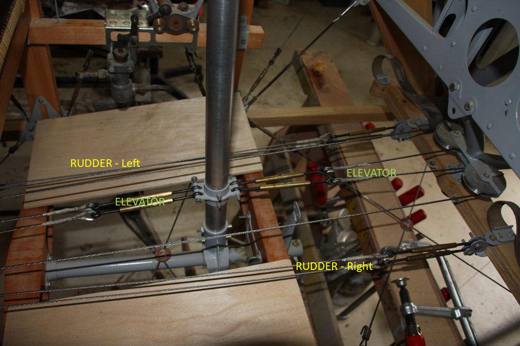
Hi Mike, I got a bit confused as to why the ailerons (i.e. the control surfaces on the wing tips) are connected to the rudder, so I did a (very short) bit of searching on google. This picture is the closest I could find to a restauration of a Sopwith camel. I have labelled the individual controls. As you can see, the Rudder controls are attached to the rudder itself, the Elevator controls are a closed loop system, apparently attached to 2 pulleys just above the rudder controls. It is not 100% clear, but I think that the rudder pedal can rotate, whyle the pulleys are attached in a fixed position on the outer shaft of the rudder assembly (a bit like fitting a light on your bycicle, you do not attach it to the shaft that connects your steering bar with the front wheel, but with the shaft housing). As I understand it, the elevators cables are not shown in this picture. They should be attached to the grey 'handle' seen just above the 1st ''R' from 'Rudder-Right', and are also in a closed loop system. Please, anybody, feel free to correct me if I am wrong in my perceptions. Hope this helps, L.H. P.S. I have re-read your previous post, and my reason for confusion is your use of 'tail aileron' to indicate the 'elevator'. My bad. P.P.S. Link to the pictures above: http://www.johnsshawaviation.co.uk/wordpress/sopwith-camel-f1-2/sopwith-camel-reconstruction/sopwith-camel-metalwork-parts/sopwith-camel-construction-upper-wings/
-
Not entirely correct, but sufficient for purpose of explanation. Asume for a moment that an airplane can rotate along three axis that converge to a single point located where the pilot sits. Let's call X-axis the one running along the centerline in a fore-aft direction, the Y-axis running perpendicular in the horizontal plane and the Z-asix runs perpendicular in the vertical plane. In order to rotate a plane along the X-axis, the pilot operates the ailerons by moving the stick sideways. If turning left, the stick is moved left which in turns moves the ailerons in different directions: the right hand aileron will go DOWN (to increase the lift on the tip of the right hand wing) while the left hand aileron goes UP (to decrease lift on that wingtip). The resulting forces around the centre of gravity(the point connecting the three axis of rotation) will mean that the aircraft will rotate to the left. The speed of rotation is directly proportional to the size of the stick movement. Similarly, rotating along the Y- axis means the stick is pulled back/forward which in turn moves the horizontal stabilizer (the flat part of the tail structure) up/down. Rotating along the Z axis is done by pushing the rudder pedals left/right as eplained in your post. Now it gets a bit more complicated: Each action of ailerons and rudder produces a secondary effect (a side effect if you will). When using the rudders each wing tip of the main wing is now subject to different airspeeds, resulting in different amounts of lift. This causes the plane to start rotating along the X axis as well as the pimary goal: rotating along the Z-axis. Similar but reversed for the ailerons because of a very subtle change in airflow around the rudder. Now, it is much easier to control the heading (direction of flight) using the ailerons than it is using the rudder. Thus a pilot will change his heading by moving the rudder left/right, and gently counteracting the secondary effect with his rudder. On other thing where the rudder is vitally important is when increasing/decreasing power of the engine. On a single propellor driven aircraft the rudder is turning in a single direction. This introduces a torque along the X-axis making the aircraft turn away from its course along the Z-axis (this is called precession, and is used to great benifit in systems such as navigational instruments but also in steadying guns on a modern warship). So a pilot taking off will need to press a particular ruder pedal harder (depending on which direction your propellor turns - this should not make a difference when modelling the plane except when telling the story as in a diorama) in order to keep a straight flight path (as in along the length of the runway). Hope this helps. Slainte L.H.
-
I love the bit about 'the future one'
-
Nae worries aboot being thick, you should meet some of my previous managers . Two, short, fat planks springs to mind when I think of them. Not quit Highlands at the mo (more south of Glaschu), but Highlander in heart anyway. If the paper analogy helps, glue two pieces of paper together, the bottom mor in a tube, the top almost flat. Give the top a hollowed out shape, then twist the tip while holding the bottom in position. Should be close enough to help you see it. Slainte L.H.
-
extra note, now I think of it. Do not take the difference in angle between root of propellor and tip as exact. It is an exageration to help you visualise things. L.H.