Supplies of the Ship Modeler's Handbook are running out. Get your copy NOW before they are gone! Click on photo to order.
×


Landrotten Highlander
-
Posts
269 -
Joined
-
Last visited
Content Type
Profiles
Forums
Gallery
Events
Everything posted by Landrotten Highlander
-
Hi Wyzwyk, I have recently started a build log on the HMS Sphinx. Scratch build based on Alex's plans, and I want to show both building methods and life on board on the same model. Should prove a challange Peter
-
Hi Sal, if you don't mind I shall pull up a chair - you may have the chain .Peter
-
Could somebody clarify why there are hinges on the supports/vertical struts? Slainte Peter
-
Hi Bob, this build has been an inspiration. Hope that I can reach this level when I do mine (kit is already in the to-do pile). Slainte Peter
- 196 replies
-
- 3
-

-
- higaki kaisen
- woody joe
- (and 1 more)
-
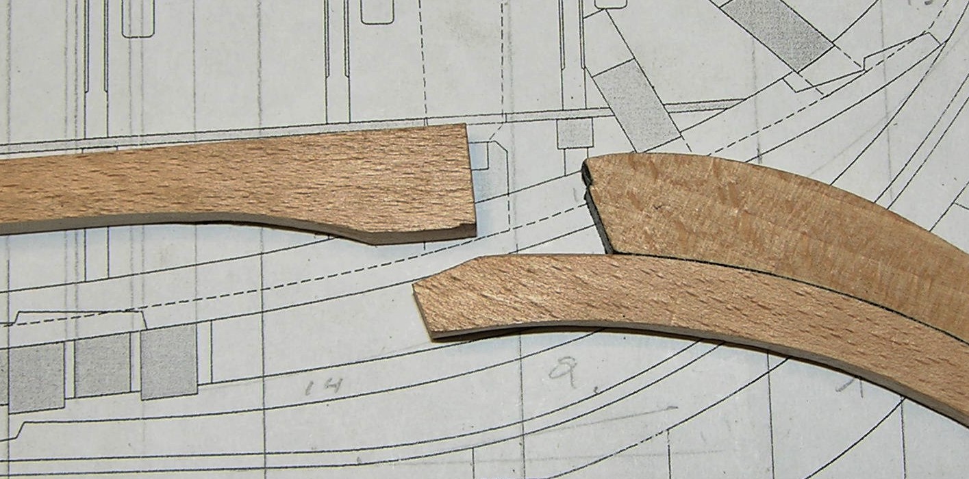
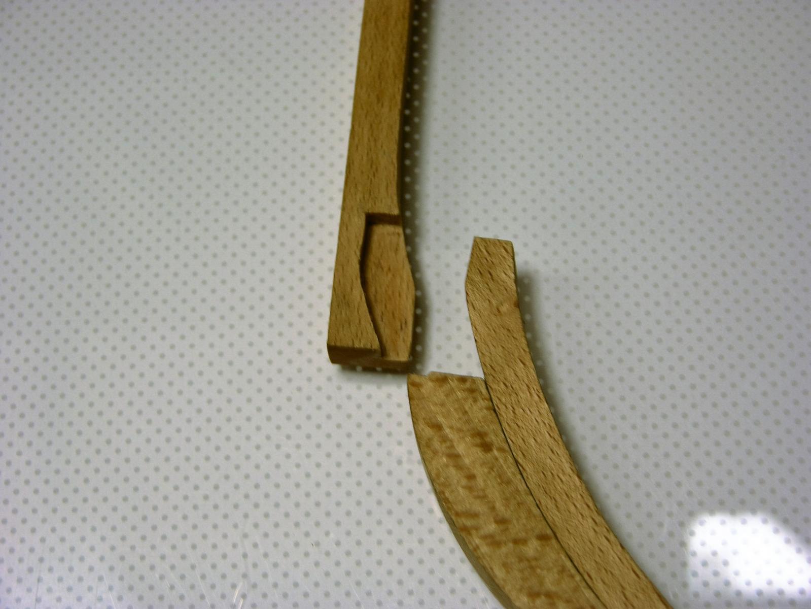
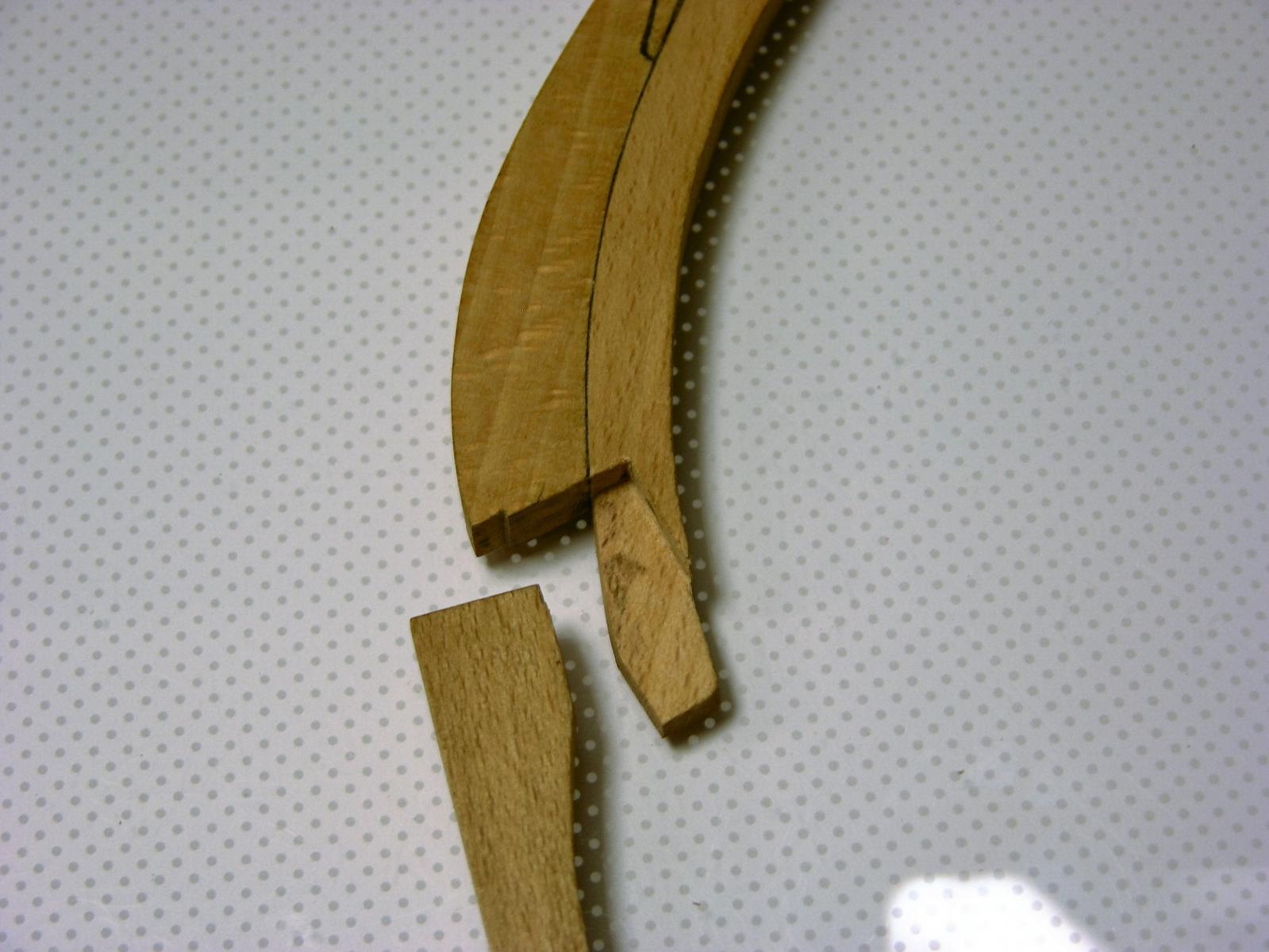
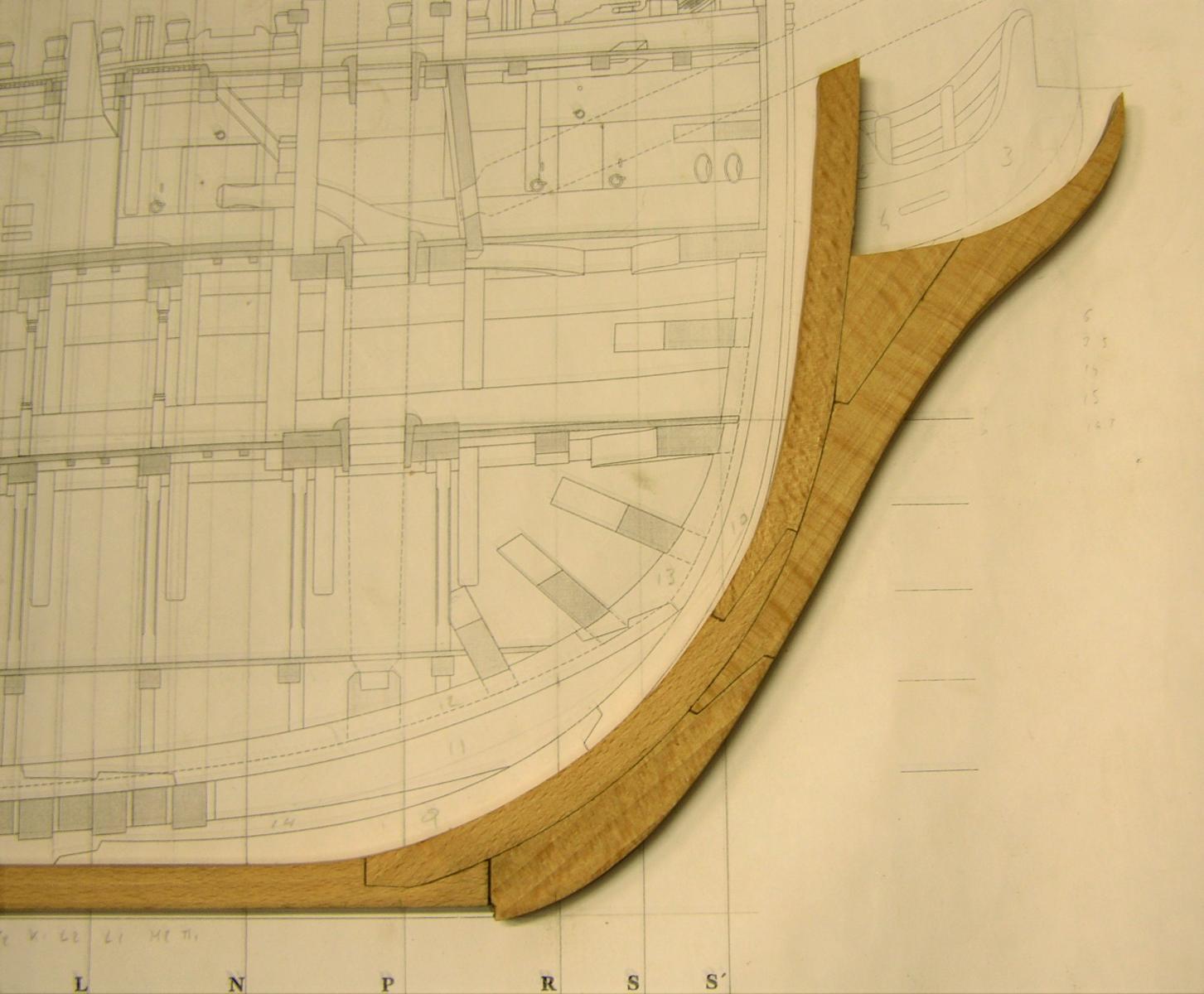
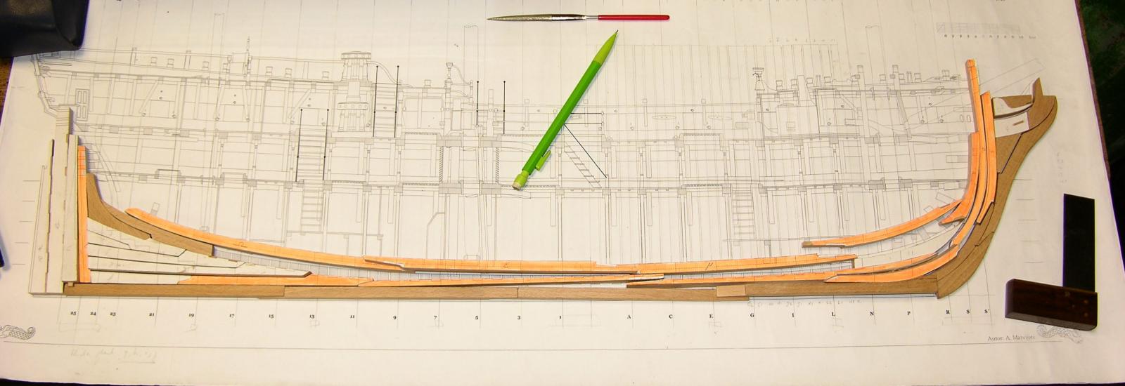
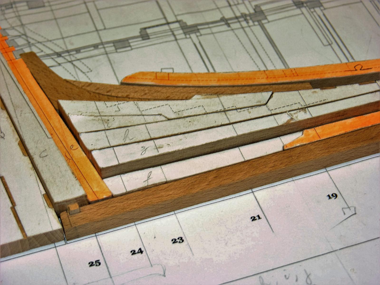
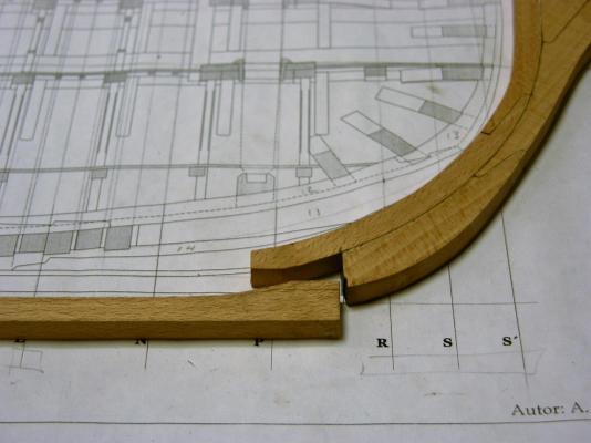
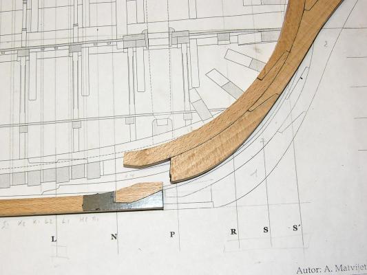
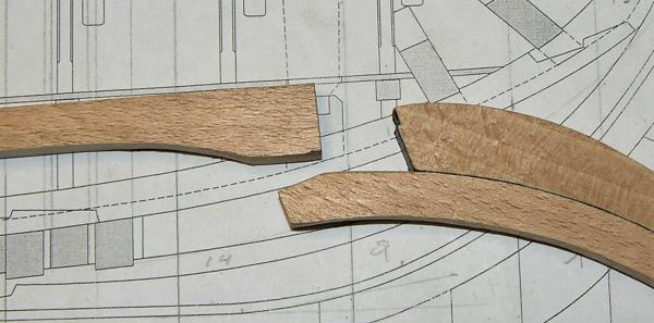
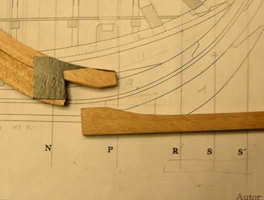
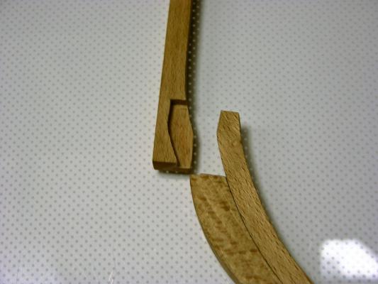
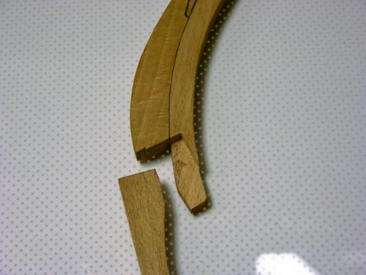
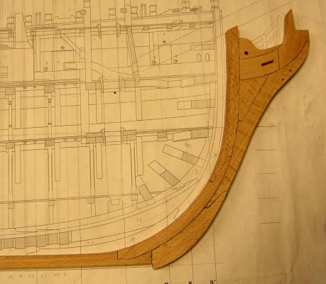
Hi All, time for a small update. Having started the build-up of the stern deadwood (and while the glue was setting) I focussed my attention to the bow. There is a complicated scarph joint which I tackled with the following technique: The joint in question: I used electricians insulating tape to mark where I should remove wood: This is the result: The depth of the scarph is about half the width of the keel: Even though I was very carefull to align all pieces correctly when marking (and gluing), and cut exactly along the lines I had marked, it transpired that I was off-kilter by a very small amount (but still too much to my liking): Some careful pushing of the wood proved to me that it was possible to obtain the correct angle without breaking the wood. However, I did not want any stress in the wood to develop (at least not at this early point in the build). Then I remembered one of the tips from Chuck - he uses and heat gun to bend planks while planking a hull. So I decided to give it a try before remaking the bow. It turned out to be a success. The keel is straight, the bow has a much better rake (angle) - at least one I can live with - and has kept that angle for several months now. Here is a picture of the bow a few weeks after trial using my industrial heat gun (heat reaches 840 degrees Celcius): When using that gun I have to be careful of a number of things: not scorching the wood, trying to avoid scorching any paper underneath - and keeping my fingers from getting burned (it is blooming hot, I can tell ya). That's all folks slainte Peter

-
hi Dan, sorry for asking, but when you say The beams are "let in" (i.e. notched) to the deck clamps by 1" : does that mean that thedesk-clamps are notched, or the deck beams? Slainte Peter
-
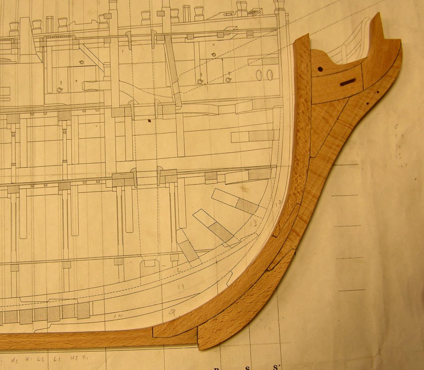
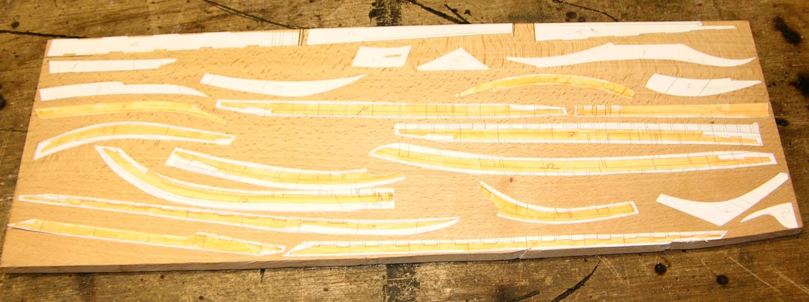
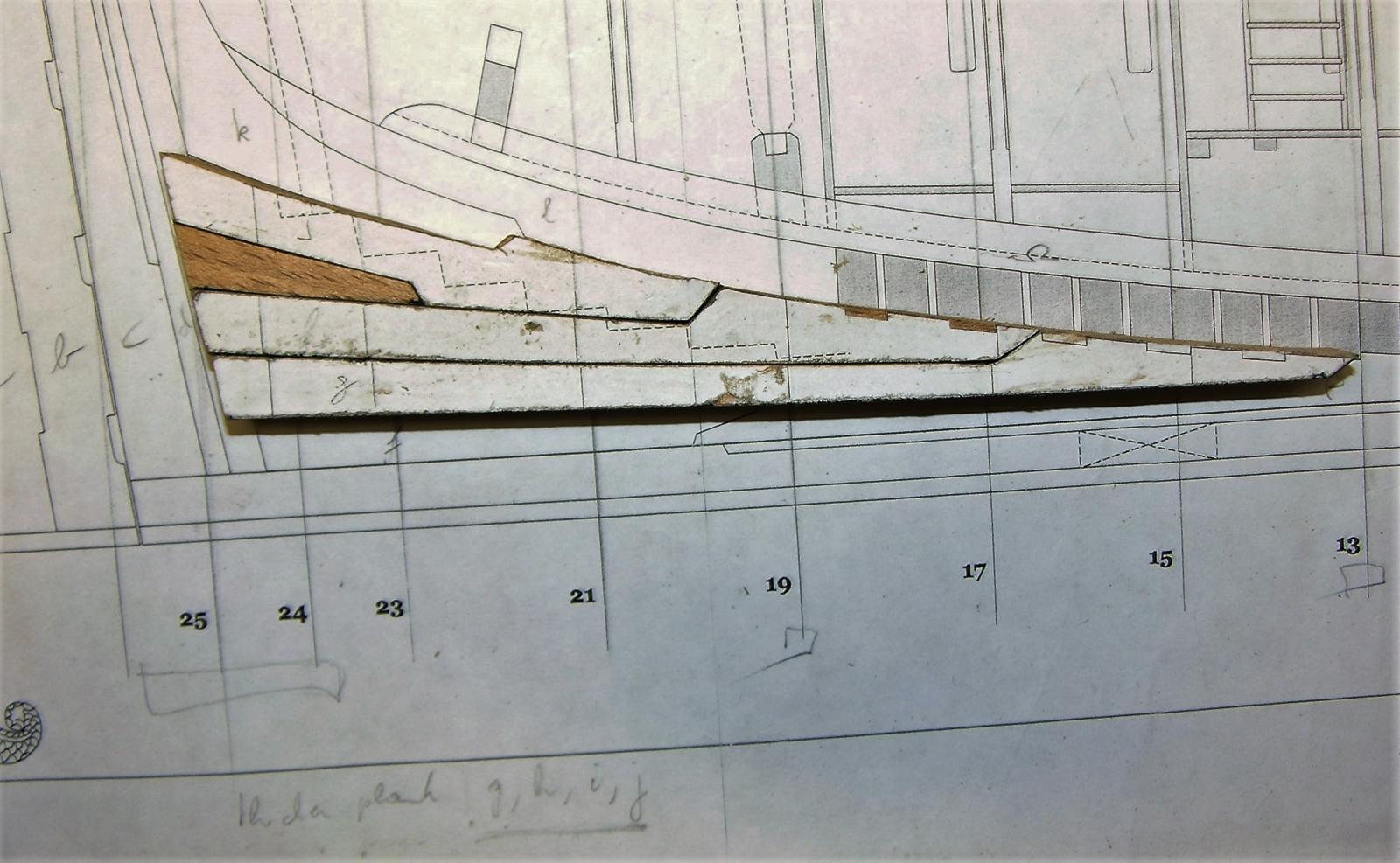
Thanks for everybody looking in and commenting. Each of your comments is welcome - as I said before, this is my first project, and is focussed on the learning curve - working with predominently wood (instead of solely with metals) and understanding both the meaning of the lines in the plans, as well as the thinking of the shipbuilders of the time. I think it is time for some pictures. First I copied the plans (multiple times) and cut out what I understood were the different parts of the keel, hog, bow, deadwood and rising wood. These were glued onto a piece of beech board. I tried to pay attention to the grain of the wood, and align each piece as best as I could with this grain. This because as I understand it is done to obtain the best resistance to deformation while building a vessel - in other words, the tree trunks were specially selected to accomodate the shap into their grain patterns. Each piece was cut out with some extra wood, then sanded to shape. The first thing I learned was the importance of angles: it is very important that right angles are exatly 90 degrees, not 91 or 89, as this will greatly affect how well the pieces align when glued together. Here are all the pieces laid out on the plan - nothing has been sanded to its final shape I refer regularly to Peter Goodwin's The Construction and Fitting of the Sailing Man of War 1650-1850 and Brian Lavery's The Ship of the Line, Volume II: Design, construction and fittings. As I understand the construction of the stern deadwood, it gradually thickens from thinner than the width of the keel just above the rabbit line, to the thickness required to seat the stern half-frames. As I was unsure exactly where this started and ended, I lofted the various station lines of the entire stern deadwood onto a single piece of paper. This enabled me to better understand the shape of the wood, and help me in assessing how to tackle that particular challenge. I decided to cut the appropriate pieces of stern deadwood from beech stock that was nearly twice as thick as my keel section (13mm versus 7mm). The first picture shows the relative thickness of the different pieces making up the deadwood, the last shows all the pieces that I thought neede to be thicker than the keel. I am aware at this point that most of them are far too thick, but better to have to cut away than to glue back on, I think. Slainte Peter


-
Hi Gaetan, thanks for the heads-up. As I said, the ship takes my fancy, but I am at this time in no condition (experience wise) to take on this project. This is why I build this ship first. I know, different country = different building styles. But the basics of working with wood, and understanding what the different lines in the plans represent is something I will be able to transfer (or so I like to think?) So when the time comes, I will defenetely bring up the subject well in advance of generating sawdust. Peter
-
What I like about the Nikon and Canon pictures is there enhanced feeling of debt - makes you forget you are looking at a model.
- 728 replies
-
- 3
-
-
- le fleuron
- 64 gun
- (and 1 more)
-
Regarding my choise of beech as a material I would like to tell you the reasons. 1) My local lumberyard had other woods available, such as cherry or pear. However, all those boards showed signs of spalting (i.e. it had lighter streaks across the board. And the local hobby shop only had balsa wood - which is much softer than pear. I have used this wood for modelling concepts of ideas as it was conveninet, but never liked the softness of it. Getting other woods - say pear - would mean that I would have to order this in specialist shops, and the only ones I could find that had the sizes I needed were 'over the pond and across the water', meaning it was a) more expensive and would cost almost as much to get it to me. The beech wood boards all had a reasonable even colour - and NO spalting. 2) I understand that traditionally pear is being used a lot. But as this is my first scratch build I was thinking it better to start with a wood that is easy to get - and this relatively cheap - as it allows me to make mistakes during the learning a less costly affair. And I mean this not only in monitary ways. As a Bonsai artist I learned my skills on material that had good potential (usually from the local nursery), and was relatively cheap and readily available at the time. However, fast forward 10-15 years and I am regretting losing so many good potential Bonsai due to my inexperience. Now the same type of material is very hard to come by (most nurseries no longer grow trees for the required length of time - and thusthey are a lot more expensive. It has now gone so far that I have decided to invest a lot of money in starting a specialised nursery growing trees with potential towards Bonsai. However, as that takes a minimum of 5 years - but more like 15-20 years - I do not expect to make a lot of money out of it. But perhaps however takes over the nursery in (hopefully a few decades time) will be able to make a decent living out of it. So going back to topic. I felt that beech would enable me to obtain/refine my skills sufficiently, while learning how to build a ship, so that for my next project I can take on the build without the many questions and insecurities I have at present. By then I will have obtained a method of working, and acquire the necessary knowledge and tools to bring it to a successful end. Peter
-
Hi Gaetan, can you explain the reason why my choise is not good? Or is it simply a case of it is different than what others have done before me? I am asking as I want to understand your comment, rather than copy it without thinking. Kind regards Peter
-
Hi Tom, cheers for your encouraging comments. Also thanks for everybody looking in and hitting the like button. I will be building this ship using beech - I managed to source some relatively locally for a good price. The lumberyard was able to cut up the wood into thinner boards - mostly 6mm thick - all with a good enough finish and even thickness across all boards. This is the maximum scale siding of the frames, and all other parts of the ship (bar the keel, which is 7mm) is less than that. As for modelling: as far as I remember I was always changing kits, as there was always something that bothered me about them. So I finally bit the bullet and decided to start from scratch. That way, if anything is not to my liking than I have only myself to blame. I am confident that my practical skills I obtained while training for a career in Engineering will help me greatly as well. And one thing I learned quit early - when making a model, go for something that tickles my (your) fancy - anything less than that and I lose interest very quickly. I am certain that there are many other (easier) ships I could start as a first scratch model. I have looked ad the Swan class as well - but the books look a bit too much like a manual to me (personal taste), and I am the type of guy that learns best if he has to find his own way (I tend to be 'why learn things the easy way when a difficult way is possible?). The Sphinx seems to be the ship that will allow me to do so - apart from which the plans Alex has provided are very detailed. He is now working on the HMS Anson (64 gun third rate). That one tickles my fancy too, as well as the French 'Fleuron' and the 'L'Ambitieux' as described by J. Boudriot. As far as helping me finding out how ships were built, I base myself on Peter Goodwin's 'Sailing man of War 1650-1850' and Brian Lavery's 'The ship of the Line'. Up to now I am happy whith the results, as you will find out in the coming weeks when I (slowly) bring all of you up to date with my work so far. Slainte Peter
-
Hi All, I have been working on this ship for a few months now. This is my first scratch build (i.e. not starting from a kit). The plans were purchased form Alexander in Germany (he has a build log on this site for the same ship). There are a number of personal requirments relating to this build: 1) I want to understand and depict how a ship was build at the time; 2) Where possible/feasible I want to show what life looked like at sea at the time; 3) It has to be at a scale where details can be seen, yet still be small enough to stay in the house (i.e. I do not need to build a massive warehouse to store this - and other - build/builds). 4) Relating to the scale again - this build will be a stepping board to a series of much more complicated builds of ships within the golden age of sail. I wish to keep the scale the same across all ships, so I can see how the size of a relatively small ship (this 6th rate, or something like the Royal Caroline) relates to something like a 1st rate. Again, the size of the largest ship will have to fit within my house. I spent a few months looking at as many build logs as possible to gain ideas as to how to tackle my wishes. A) Thinking about scale, I had two preferred sizes: 1:32 (this scale was chosen as there are good quality figurines available that require painting - another hobby of mine) and 1:48 (this scale relates to my earlier interests in moddeling: WWII aircraft). Any smaller scale and the figures lack the detail I am looking for. To facilitate making my final choice, I copied the cross section in 1:48 (the scale of the plans) and increased it to fit 1:32 (an increase of 50%). It was then that I realised that 1:32 would not meet criteria 3 and 4. So 1:48 it is. Thinking about how to depict building method and life on board, I had a number of difficulties to overcome. When looking at other build logs, it struck me that in many cases the frames were futher apart than mentioned in Peter Goodwins literature (the admiralty style shows the lines of the ship, not how it was built at the time). Furthermore, it appears to me that it is quit difficult to show details of the inside through these narrow gaps - this is a perception of mine, I may be wrong. (So criteria 1 is met, but criteria 2 is not) I have also seen models where the outer hull (planking and frames) on one side of the ship is (mostly) removed to show the inside. This fits with criteria 2, but how do I incorporate criteria 1 in this method? Also, these models kept the interior rather bare, which does not conform with the impressions I have when reading literature relating to the cramped conditions that must have existed at the time (e.g. this ship had a crew compliment of 140). Looking closer at these thought I realised that I wanted to have a combination of building a ship and fitting it into a diorama of sorts. So then I decided on the following: 1) one side of the hull (port side) will be completely planked; 2) the other side (starboard) will show how the hull was built - all frames, half frames, etc.; but no planks on the outside; 3) at the starboard side I will cut strategic openings to show specific scenes going on inside the hull; 4) the ship will be fully rigged, again showing what may happen at a particular time during the voyage. Relating to point 3 and 4 - I must make sure that all activities are related to the same point in time. For instance, It would be silly to show the raising of the anchor (below deck) while at the same time showing the stowing of sails above deck. Somehow that does not compute - the first depict the beginning of the voyage, while the last in extreme cases the en of the voyage. As this is my first scratch build, it will go slow (learning the ropes while building, so to speak). This means I have plenty of time to decide what scenes to depict. I will appreciate any input/ ideas any of you can bring. The first step is to build the empty hull to a point where decks need to be built. Slainte Peter
-
Hi Clare, I realy enjoy your builds - and like this vessel for some reason or other. Could you give us a link to the manufacturer or somebody in Japan that sells these kits? Kind regards Peter
- 51 replies
-
- 3
-
-
- wasen
- thermal studio
- (and 1 more)
-
Bolt Heads on Brass Strips
Landrotten Highlander replied to mikiek's topic in Metal Work, Soldering and Metal Fittings
suggestion: why not use a brass rod of a diameter similar to the length of the diagonal of the bolt. Drill a hole where the bolt is supposed to go. insert the rod and fix (solder or glue). Then carefully file the rod to the height and squareness you look for. -
I have my chair booked, keeping an eye open for this one as well
-
Have you considered jin-fluid as sold in Bonsai businesses? It is LOC and comes in usefull small packages (from 250ml to 1l bottles).
- 1,207 replies
-
- 2
-
-
- sloop
- kingfisher
- (and 1 more)
-
In my other hobby - Bonsai - we used some old haidresser's chairs. Just replace the seat with a thick board, and what you are left with is the pumping mechanism (for up-down) and the turning ability. Used to work a treat on really big Bonsai (3-4foot high).
-
Hi Piet, regarding blackining your hooks, see this topic http://modelshipworld.com/index.php/topic/1240-another-type-of-blackening-agent-and-some-experiments/?hl=%2Bblackening+%2Bbrass+%2Bglass In this method glass-staining is used to blacken soldered brass wire already attached to blocks (the whole thing is submerged in the blackening agent). Only the metal is blackened, the block remains unchanged. Perhaps an option? Peter
-
I have worked on Hawthorn wood - not in modelling but in Bonsai. It is an extremely hard wood, which will blunt your knife/power tool very quickly. Other than that it does have a very nice texture. Peter