HOLIDAY DONATION DRIVE - SUPPORT MSW - DO YOUR PART TO KEEP THIS GREAT FORUM GOING! (89 donations so far out of 49,000 members - C'mon guys!)
×


KeithAug
-
Posts
3,980 -
Joined
-
Last visited
Content Type
Profiles
Forums
Gallery
Events
Everything posted by KeithAug
-
 Good progress Ras. Here is a variation on the method of making steps if you are interested.
- 128 replies
-
- 3
-

-
- zulu
- sternwheeler
- (and 1 more)
-
A wonderfully clean build Nick. It would be interesting to know how long the various stages of build took?
- 68 replies
-
- 3
-
-
- Coates
- Rudderow-class
- (and 1 more)
-
Byrnes thickness sander for sales
KeithAug replied to scrubbyj427's topic in Modeling tools and Workshop Equipment
And popped out equally quickly! -
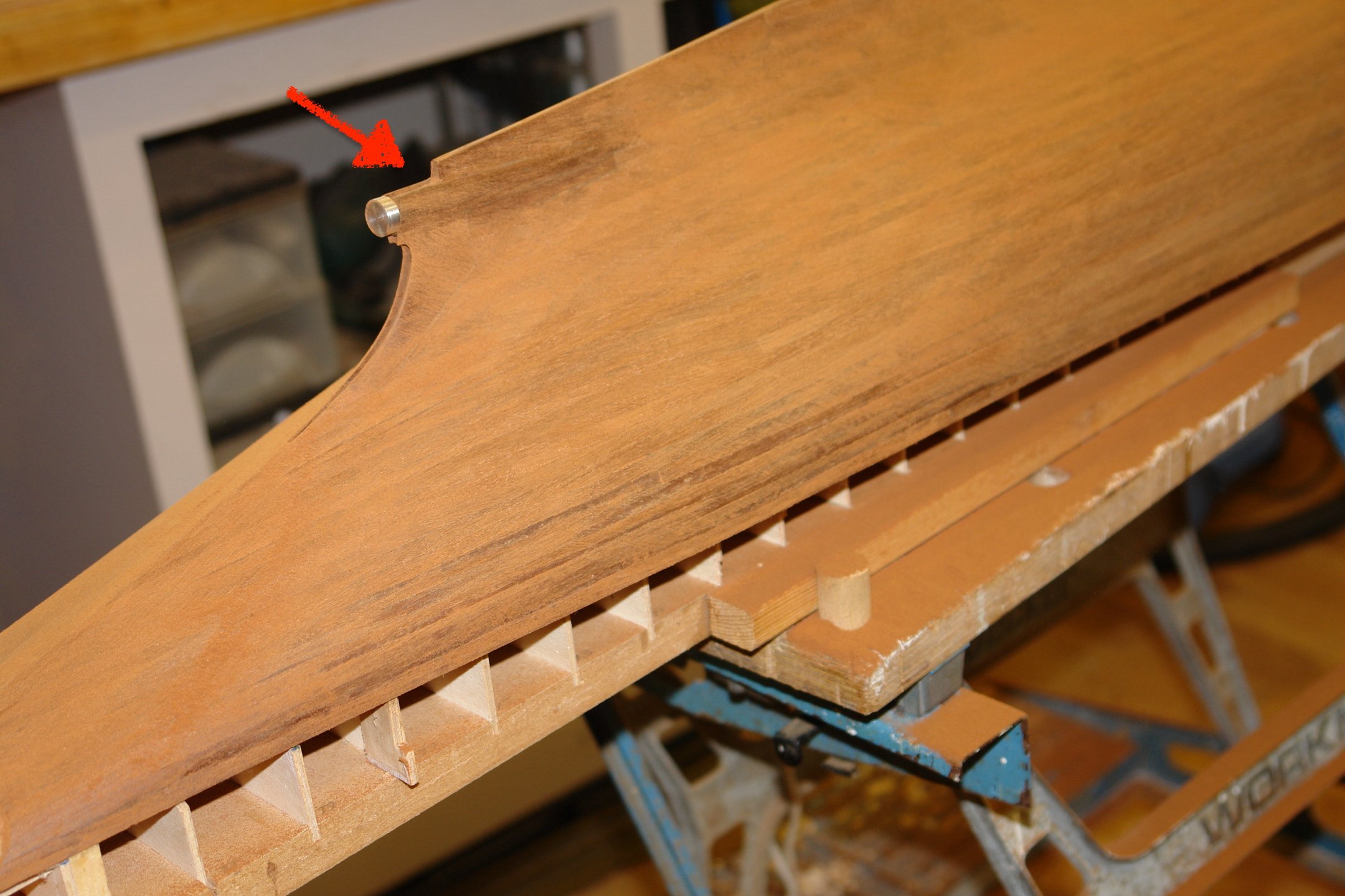
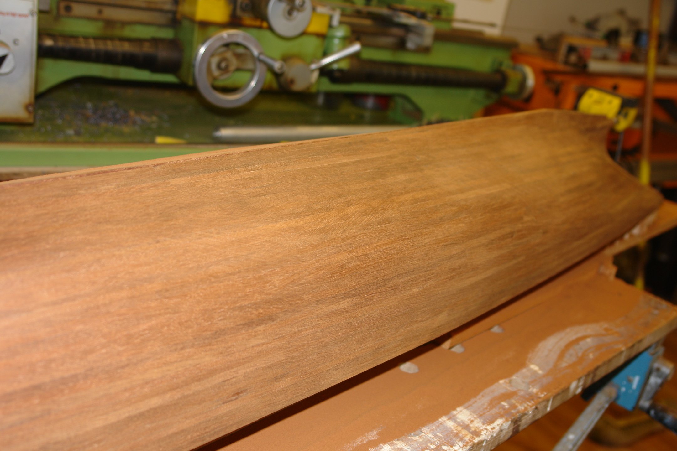
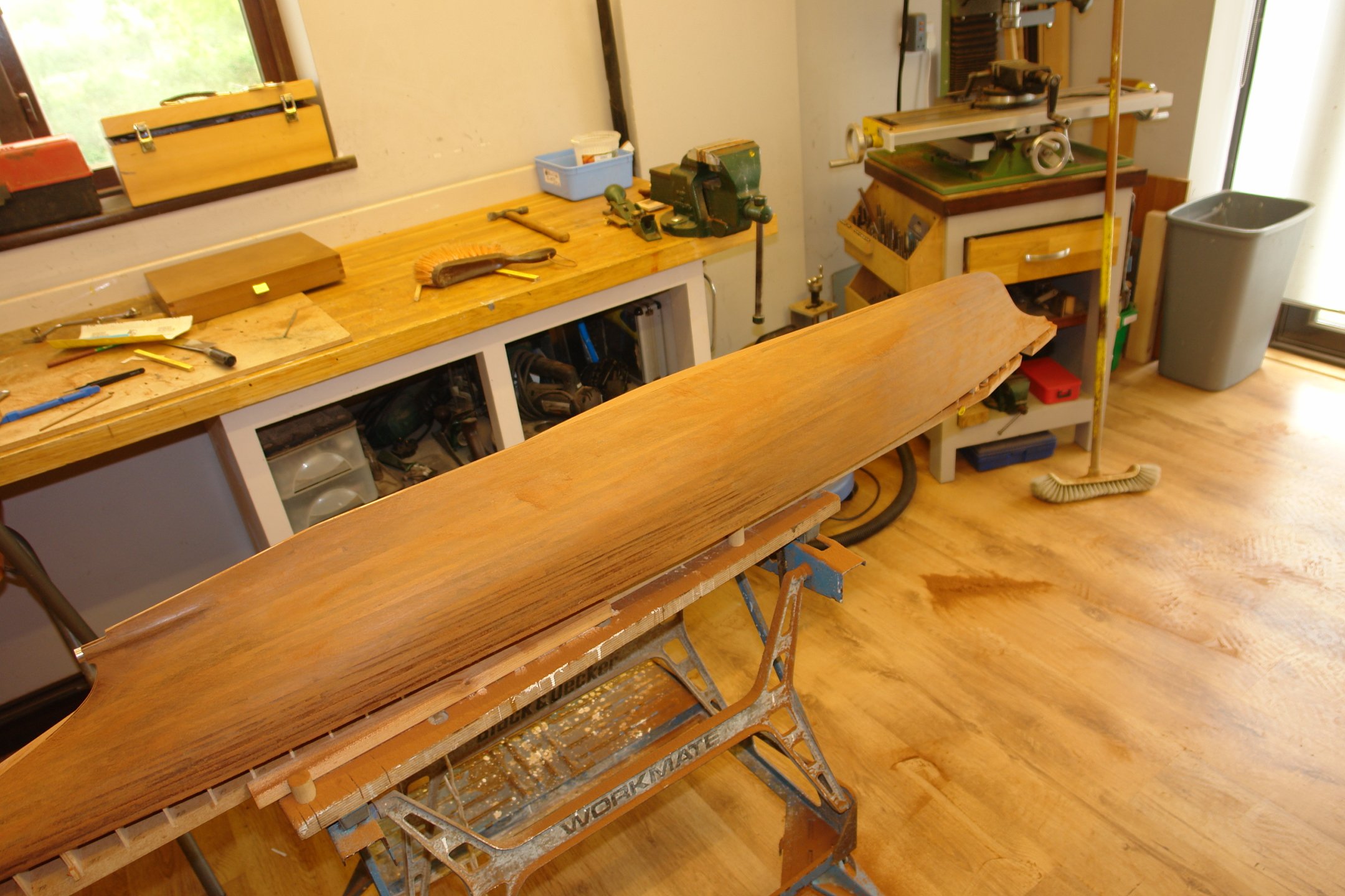
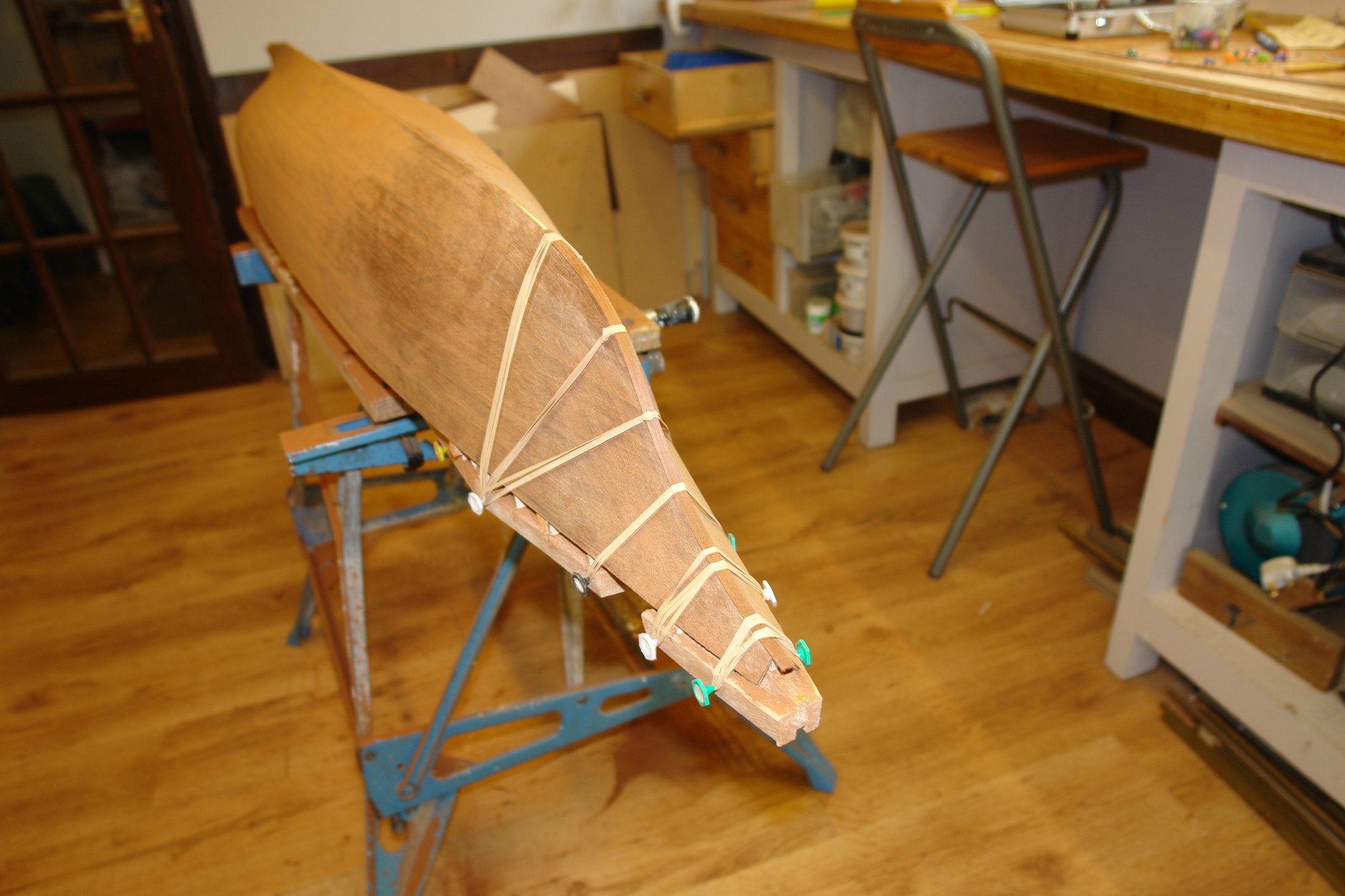
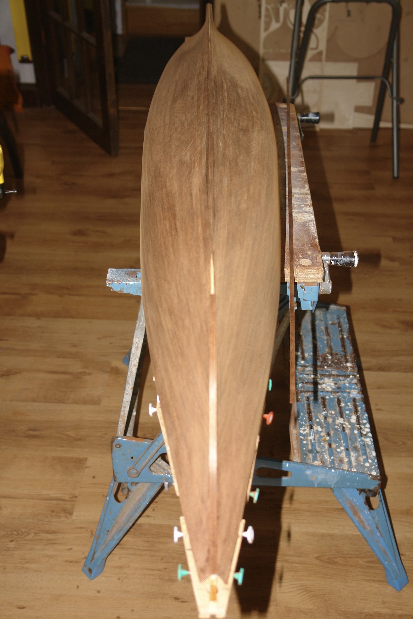
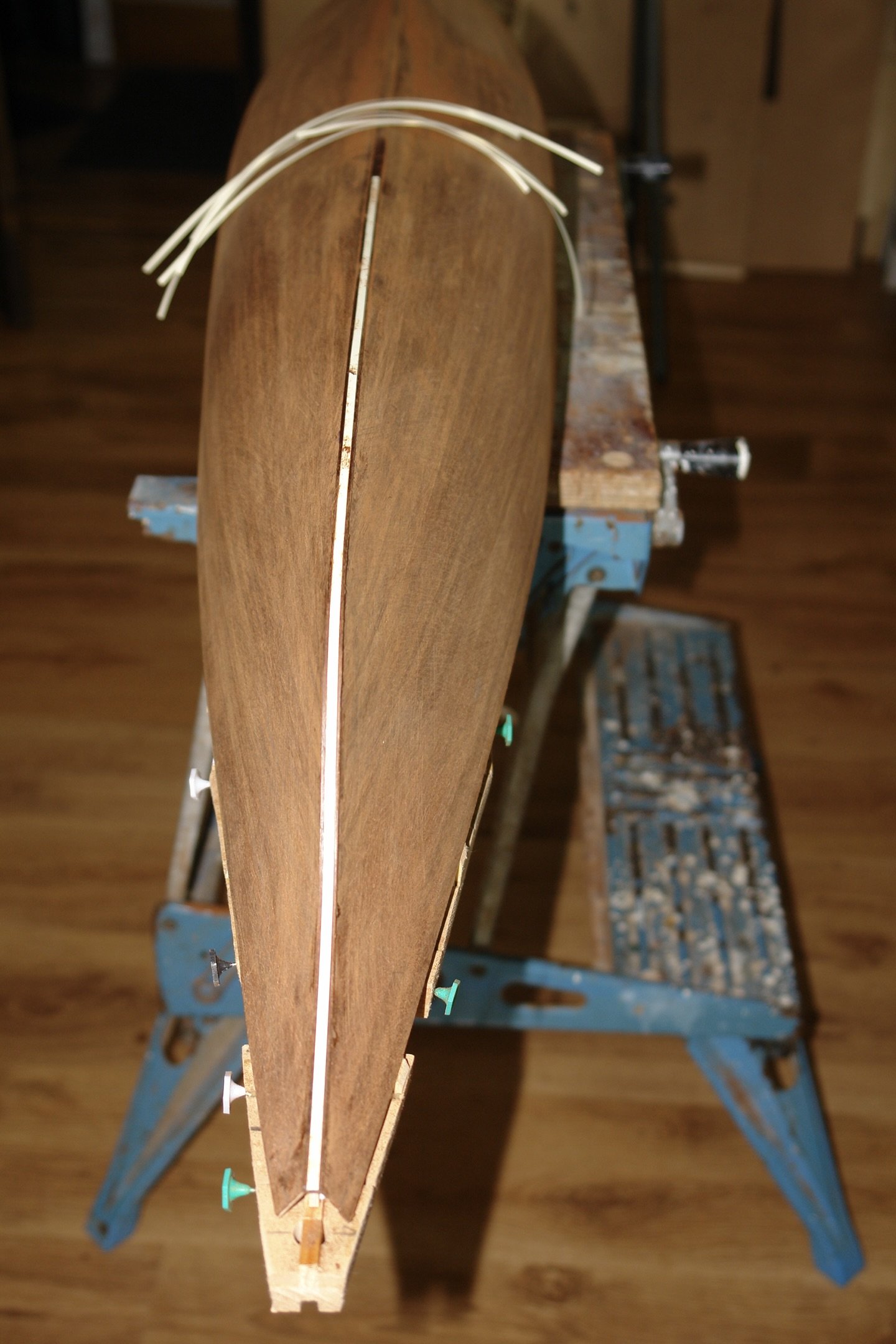
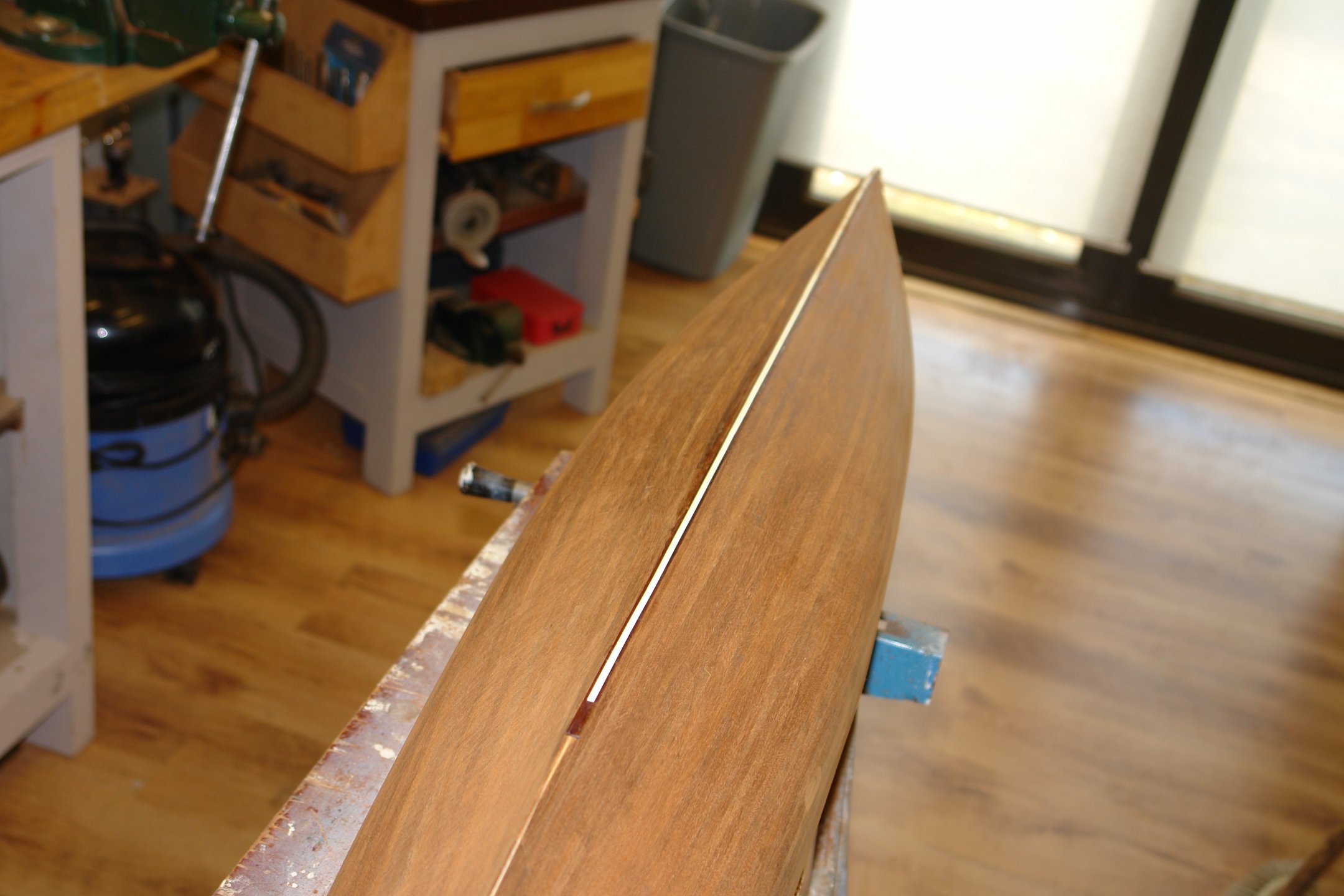
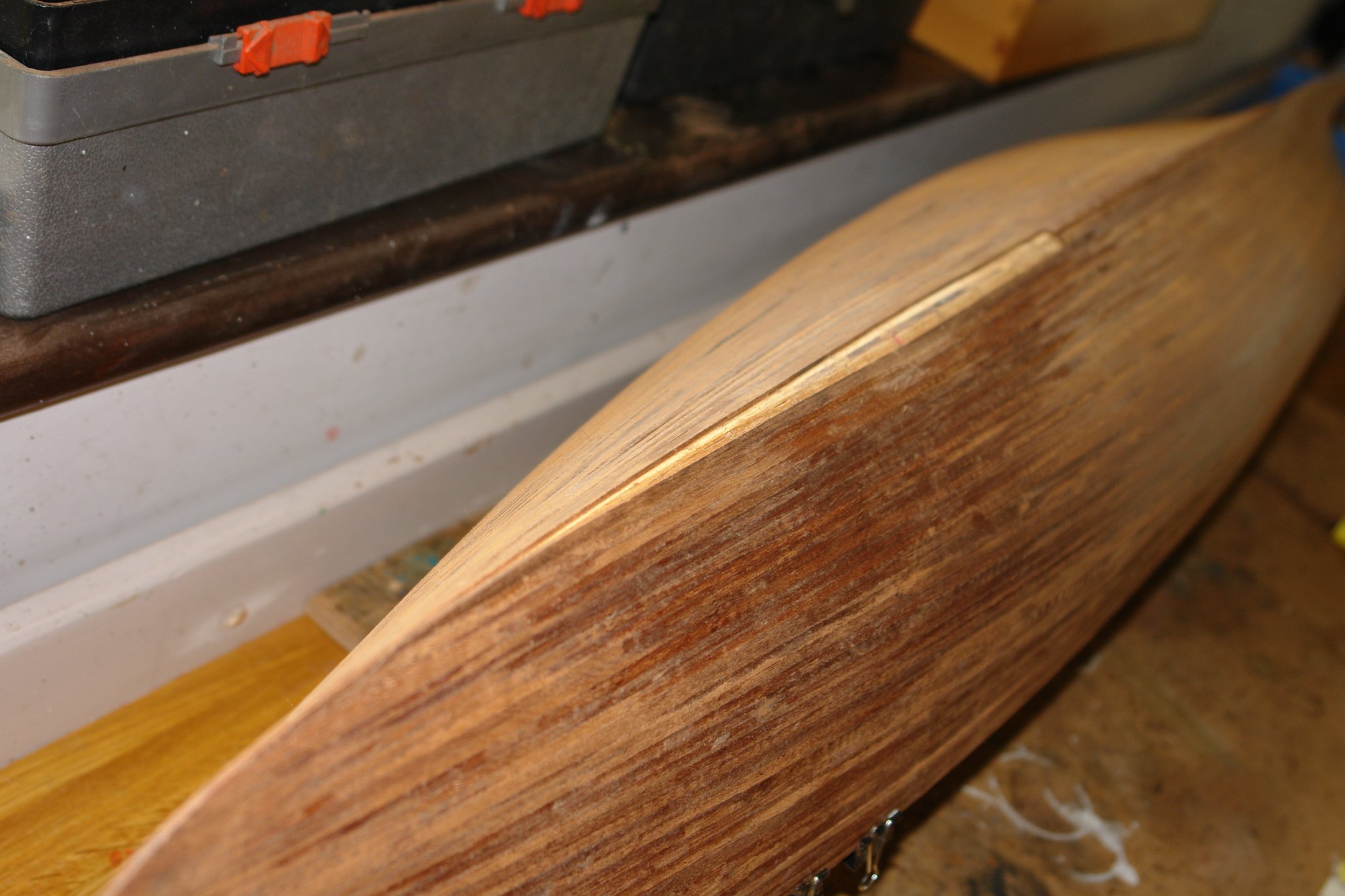
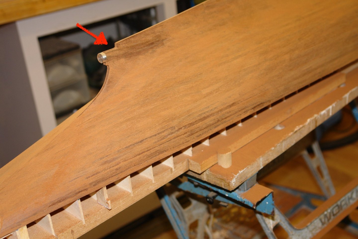
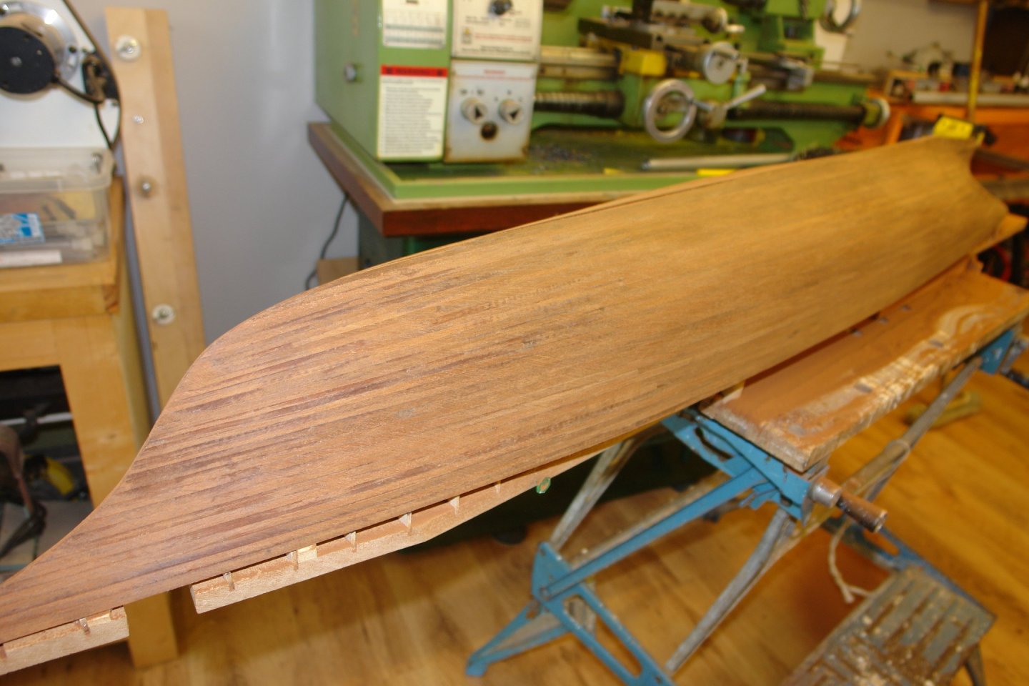
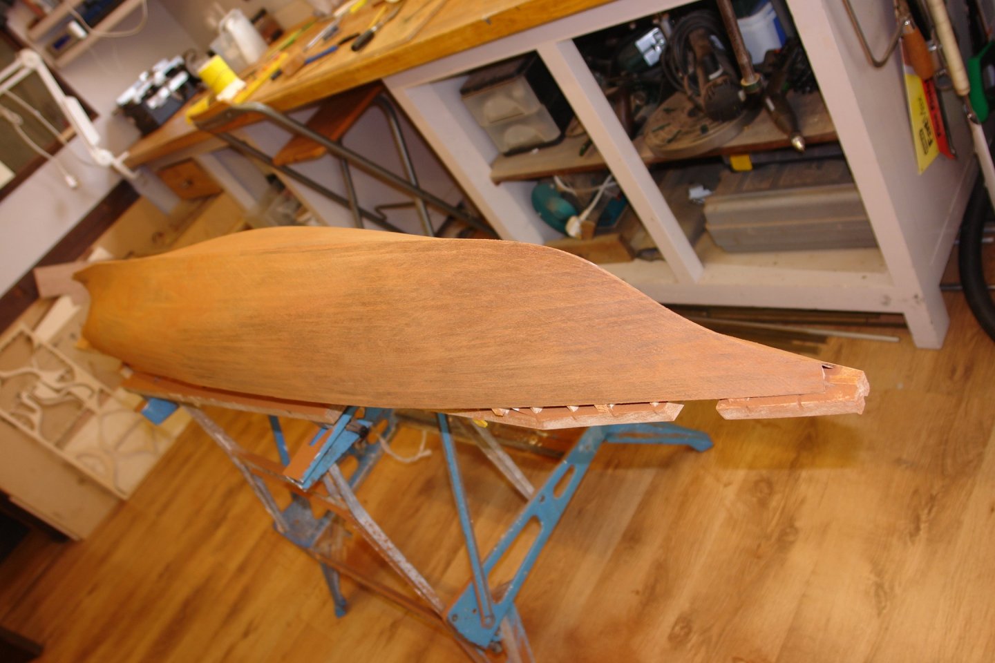
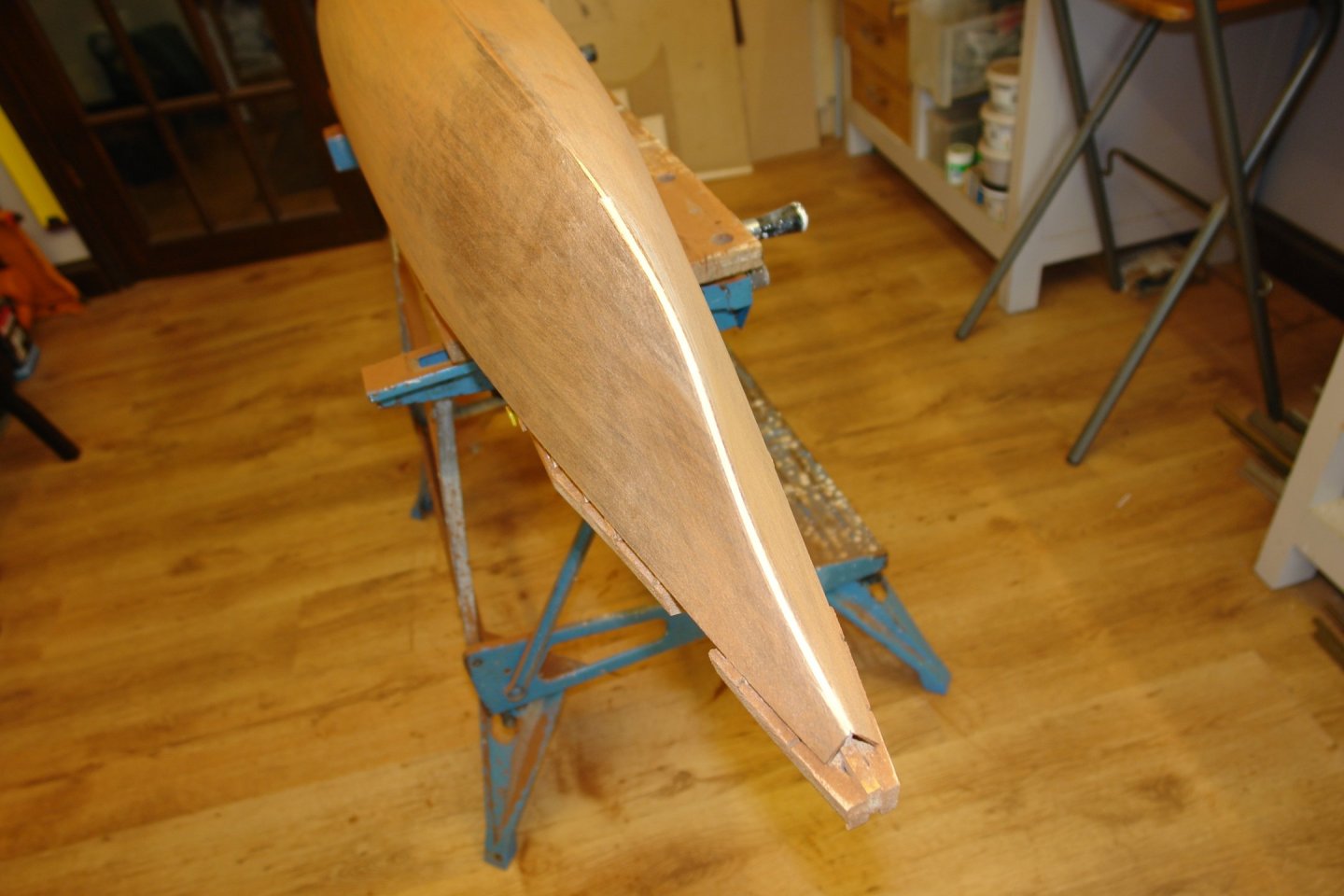
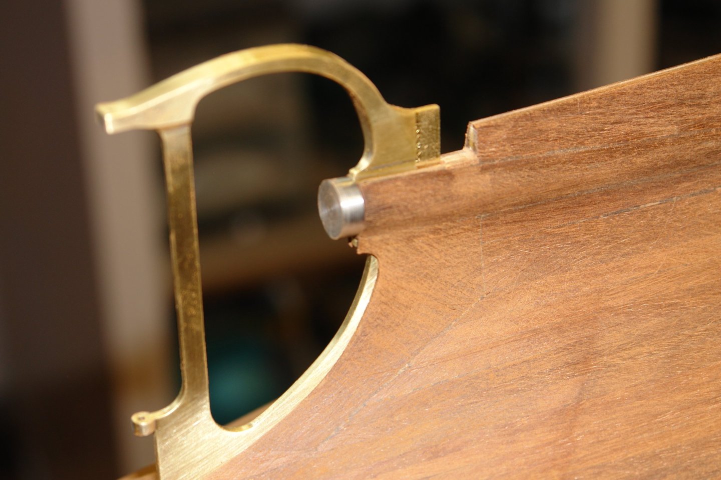
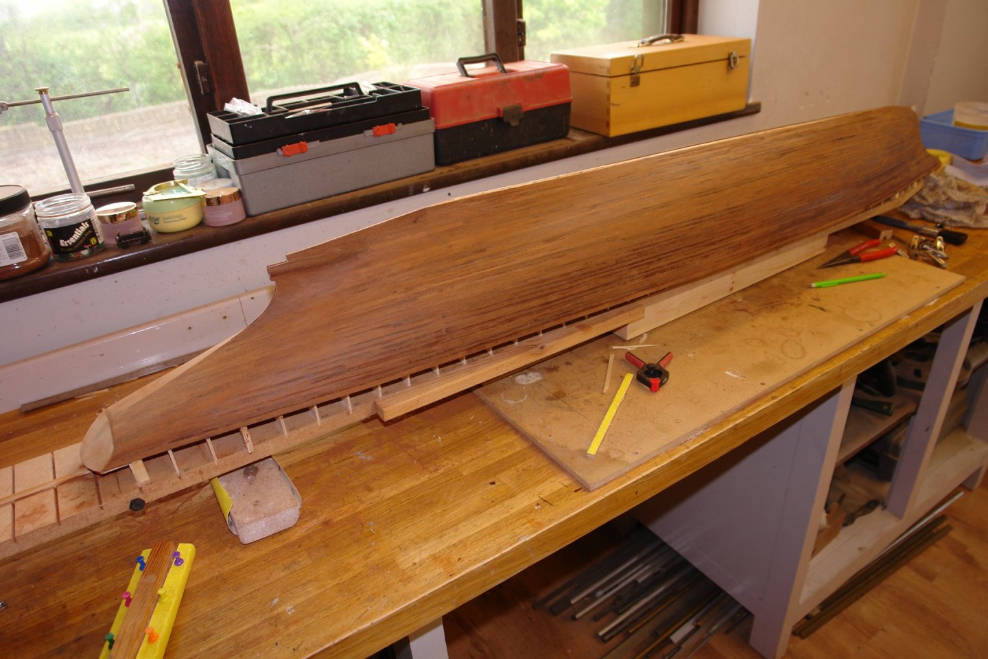
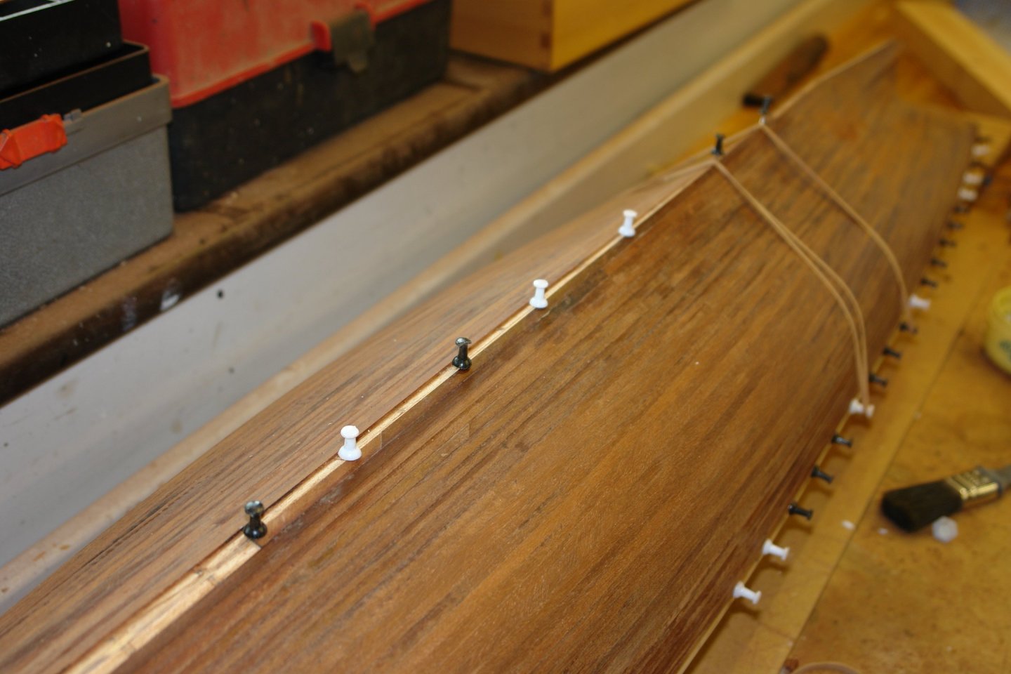
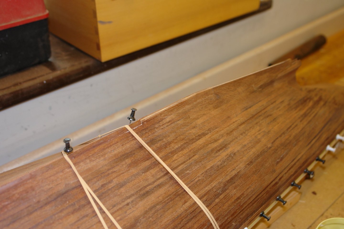
Thank you Druxey, Gary, Keith, Andy, Steve. So onward and upward. Now if you thought planking was mind blowingly boring, just draw up your seats for sanding time! Firstly though, the excitement of the week was breaking off the fragile keel end piece (red arrow). No it didn't break off neatly, the neatness comes from a bit of fettling. You can see the plank edges beginning to disappesr with the application of 80 grit aluminium oxide paper and a lot of elbow grease. I use a cork sanding block 2"x3"x"1" and one 8"x2"x3/4". No electric sanding aids for this old luddite. Note the copious amounts of dust collecting on the B&D Workmate. To feel that I am making some progress I work my way around the hull progressively. The planking job seems to be handling the reveal quite well for the moment. The "sanding through the planks tension" builds just like electric car range anxiety. I comfort myself by starting to draw pictures in the sanding dust. To break the excitement I pick up the broom and do a bit of dust mountain creation on the workshop floor. it was about here that I wandered into the kitchen for a cup of tea only to be thrown out because I apparently looked like the dust monster. At this point "thickness anxiety" overcame me and I switched to 120 grit. In my backward construction world it now seemed about the right time to retrofit the rabbet line. The pointy but at the front was sanded flat revealing the bow frame. This was then overlayed by a longitudinal plank over the bow and along the keel. Held in place by PVA glue, elastic bands and the "Mother of All Board Pin" (MOABp) missiles. Then along the keel with more rabbet planks. The sanding stick isn't being glued on, it s just evening out the pressure on the plank being attached below. A second rabbet plank was then attached over the first. I then cut 1/10" strips of card and pasted these along the rabbet strips as a sanding guide. The keel has yet to be attached and this will be 1/10" wide and will fit on to the landing defined by the paper strips. Then some more 120 grit sanding the fair in the rabbet strips and further smooth the hull. The planking is now of indeterminate thickness but holding up for the moment. No major planking gaffs discovered as yet. Now the detached "keel end blunder" needs to be attended to. But that is a job for next time. The skeg block is finally starting the blend into the hull. Thanks to everyone who managed to stick with it through that turgid story. That's all for now folks!


-
Bending hard brass.
KeithAug replied to navarcus's topic in Metal Work, Soldering and Metal Fittings
It must be a personal preference thing. My preferred metal for machining operations is brass. I never like working with soft brass for any machining operation. Hard brass cuts beautifully and produces an excellent finish. Soft brass tends to push away from the cutting tool leading to binding and poor surface finish. This can be mitigated to an extent by keeping the tools very sharp. I only ever soften brass to ease bending operations. -
Bending hard brass.
KeithAug replied to navarcus's topic in Metal Work, Soldering and Metal Fittings
Keeping the heat on as in the video isn't very easy with small parts unless the modeller has asbestos fingers. The heat then cool technique works just as well and doesn't hurt. -
Boys are never too old for new toys. And I bet in your head you are still young! Ask Bob his advice.
-
Nicely done Mark.
-
This luddite thought that was the only way to do it. Very good cause Andy.👏👏👏.
- 174 replies
-
- 3
-
-
- Vigilance
- Sailing Trawler
- (and 1 more)
-
Keith, is your steam donkey going to get a name? I think we could all suggest names for you to choose from. My suggestion is "Donkey Oaty".
-
Bending hard brass.
KeithAug replied to navarcus's topic in Metal Work, Soldering and Metal Fittings
I think I recognise the picture immediately above. I know that this may be a little late but to answer the question "how to bend hard brass"? Brass is quite easy to bend but needs to be treated as follows. Heat the area you want to bend using a blow torch until it glows cherry red. Let the brass cool down to room temperature (no need to quench it). Now start to bend the brass (you may need to create a jig to bend it round) As you work the brass it will start to harden again - this is called work hardening. Repeat the process of heating to cherry red followed by cooling - the brass will soften again and you can continue bending. Repeat the heating / cooling / bending process until the desired shape is achieved. -
Yes a nose job often improves the look. Craig - The hull is looking very smooth and blemish free - clearly you build process worked very well. I guess from your comments she is going to be both a working and display model. I hope she doesn't get bashed up during playtime.
-
Exciting Rob. She is a very handsome vessel but looks like quite a challenge. I'm sure you will make a treasure out of her.
-
Beautiful work Andy and very impressive building frame.
- 174 replies
-
- 4
-
-
- Vigilance
- Sailing Trawler
- (and 1 more)
-
You would be welcome Keith.
-
Wonderful Eberhard. I liked the crew pictures so much I even made my wife look at them. Even she was impressed.
-
Keith - as we have to keep you occupied for a long time we should insist you make it a working model.😬
-
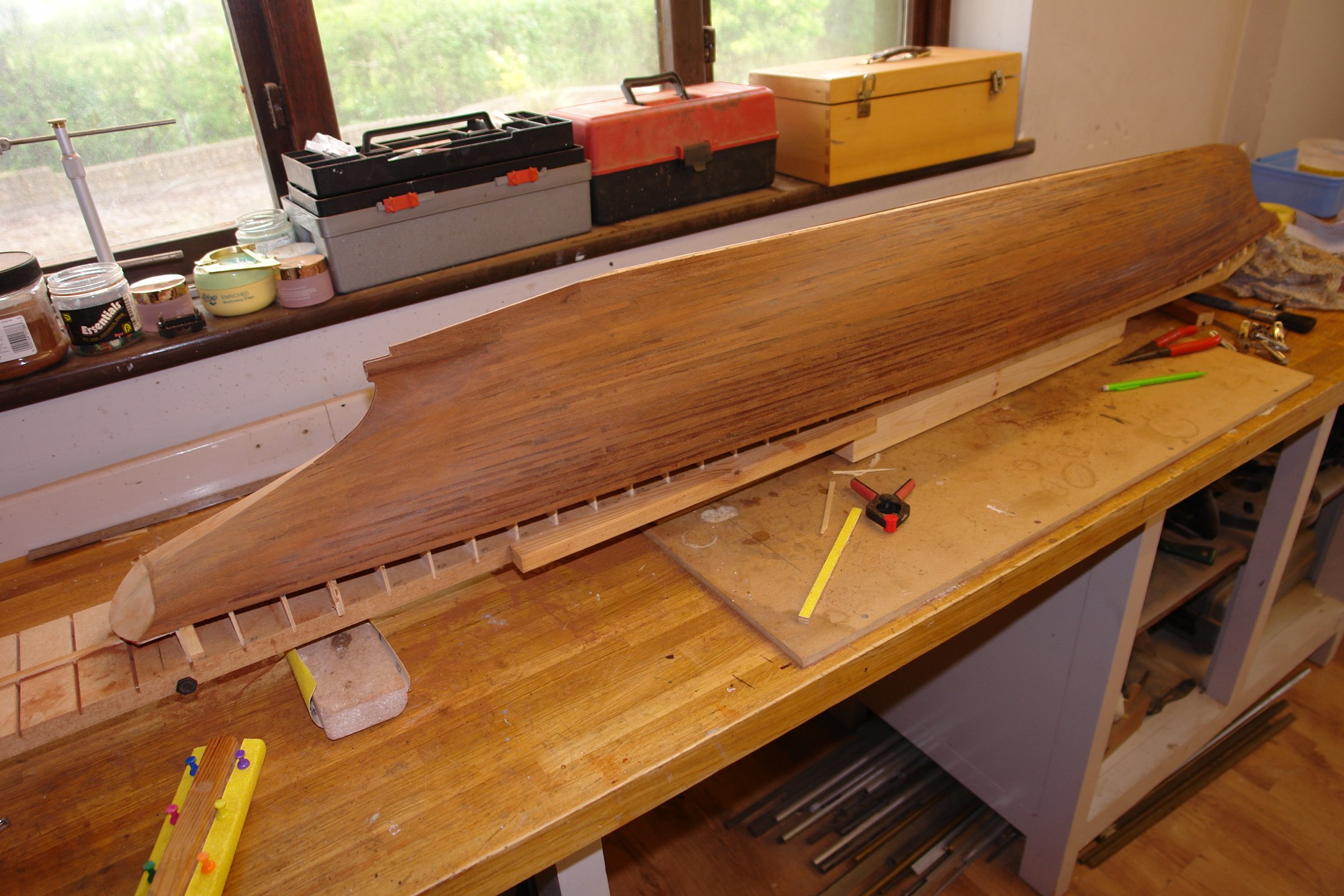
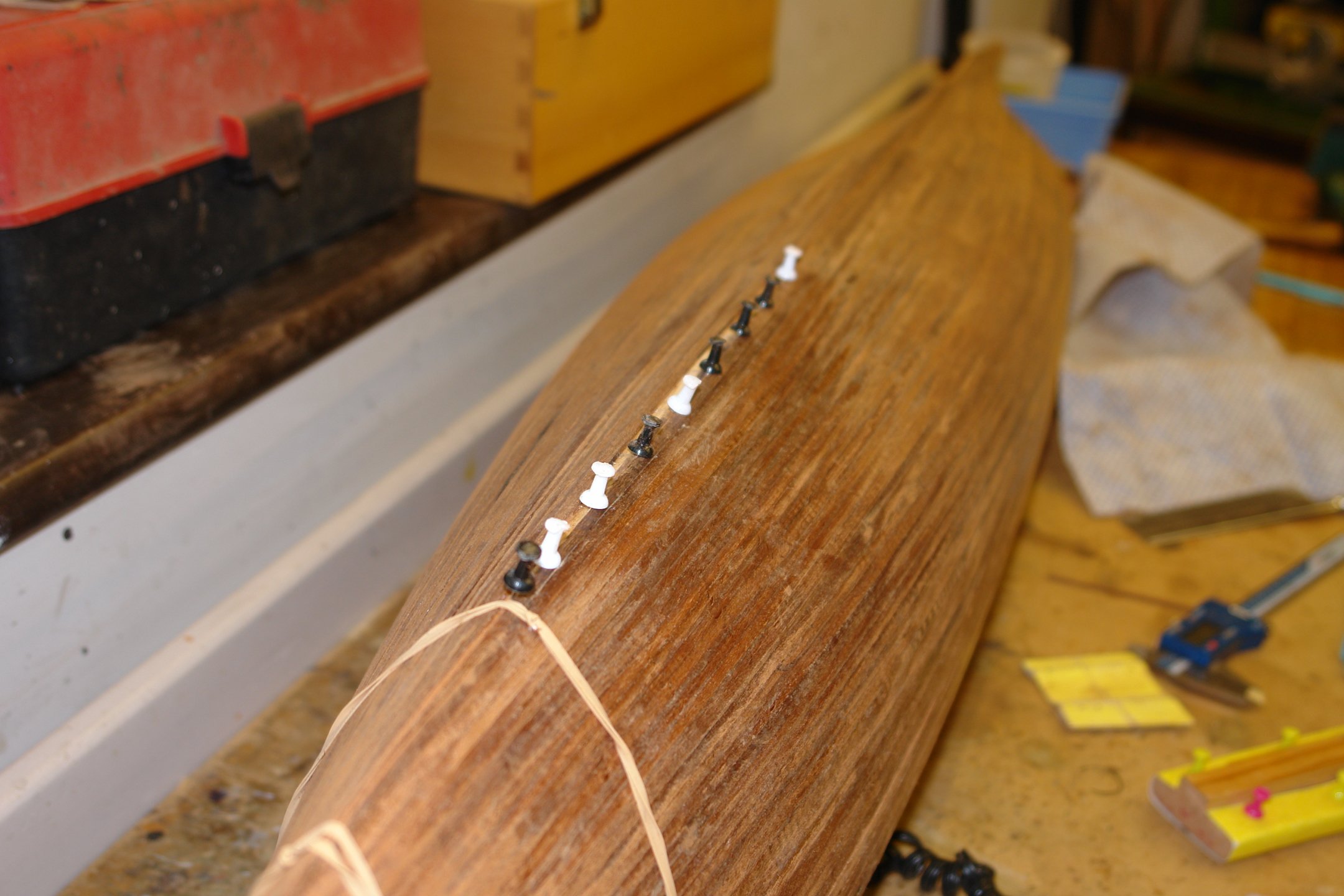
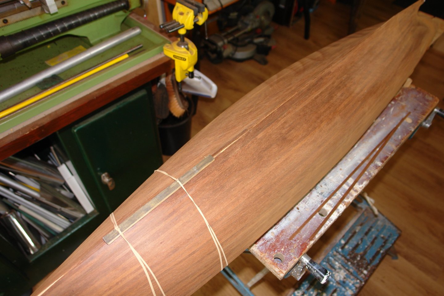
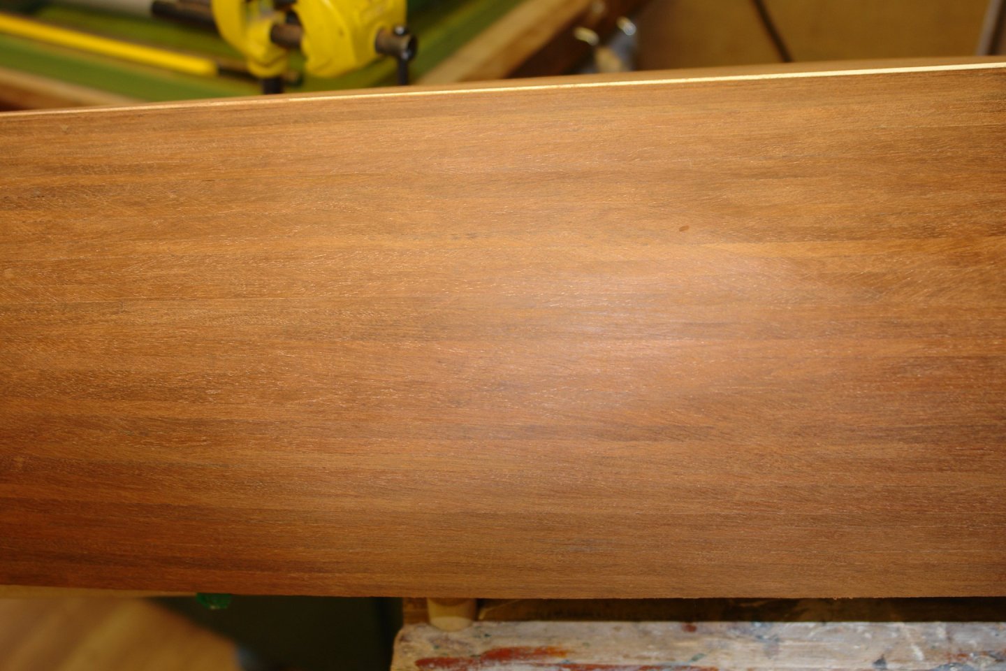
Thank you for commenting Rick, Eberhard, Druxey and Ian. And thanks to all who have liked or visited my work. A very brief update with little to show but a major milestone achieved. Having completed the bulwark planking I moved back to the keel and attached the last few planks. More potential notice board pin missiles, nervously in use. And then thankfully that was that. The next step is one of extensive sanding to get the hull smooth and sleek. I still have a lot of work to do on the hull but at least it feels like the worst is nearly over. That's all for now friends.


-
Nils - pity about that. I suspect once on display it won't be called on to function very often.
- 299 replies
-
- 5
-
-
- lightship
- Feuerschiff Elbe 1
- (and 1 more)
-
Then you had better make it last a few decades. No early retirement for you.
-
Looks fascinating Keith - I will be following. Have you agreed the project with Ole Bob?
-
Very nice - are the brass parts Photo etched? The white metal parts look like castings did you do the casting.
- 68 replies
-
- 3
-
-
- Coates
- Rudderow-class
- (and 1 more)
-
Looking good Nils. Did the gravity davits work Ok?
- 299 replies
-
- 5
-
-
- lightship
- Feuerschiff Elbe 1
- (and 1 more)