KeithAug
-
Posts
3,986 -
Joined
-
Last visited
Content Type
Profiles
Forums
Gallery
Events
Everything posted by KeithAug
-
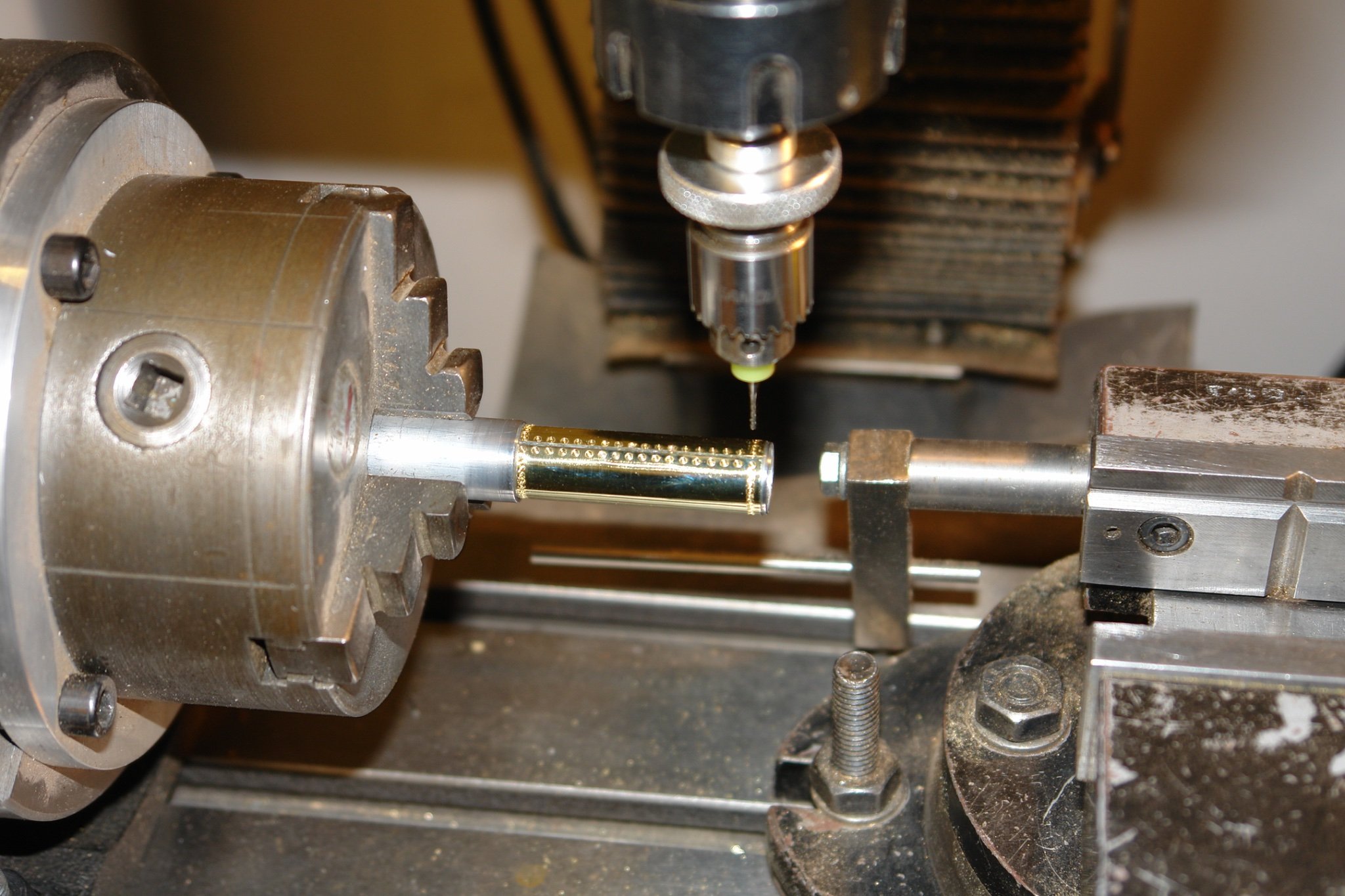
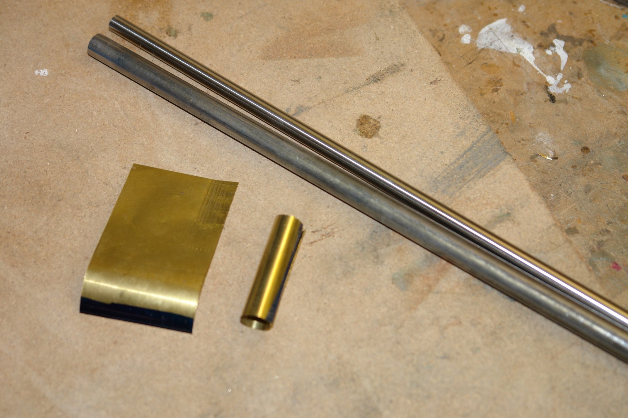
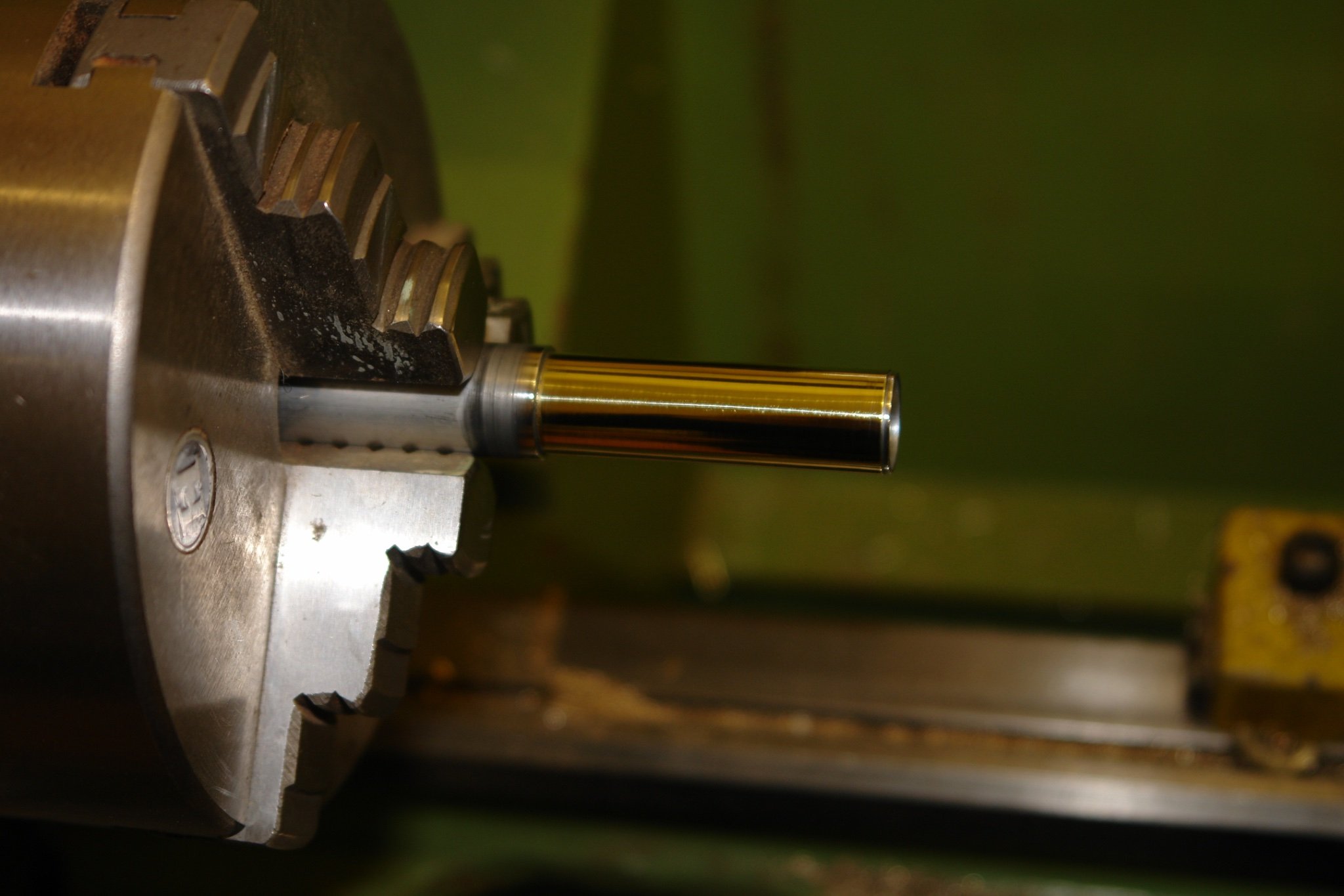
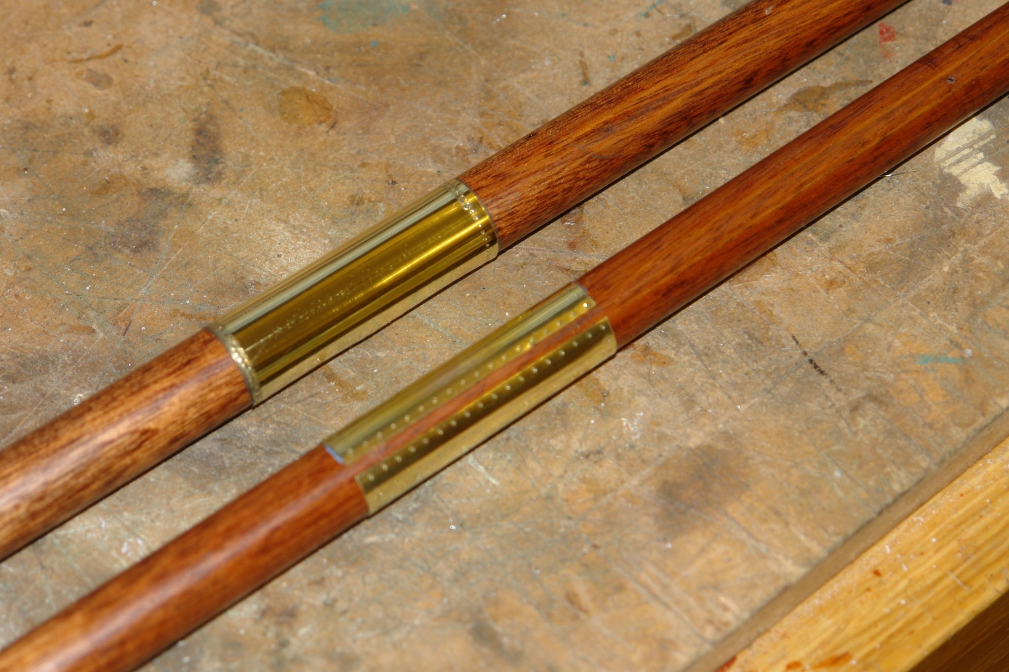
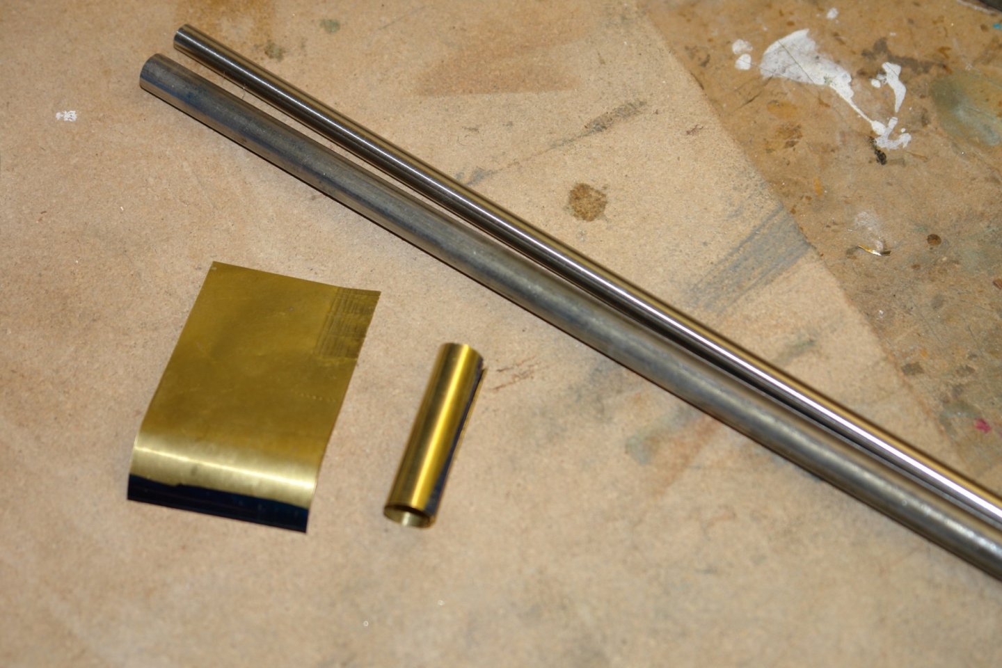
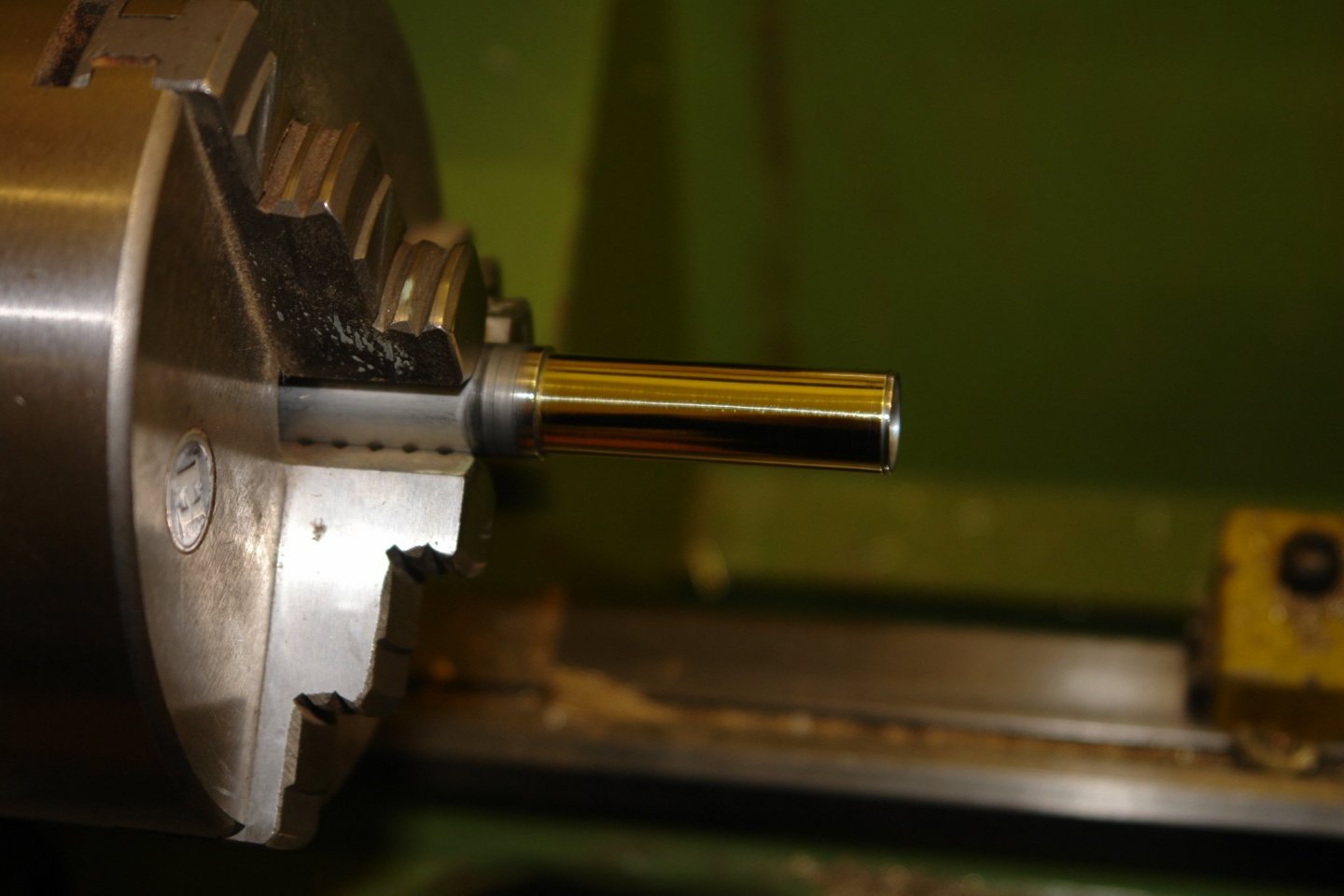
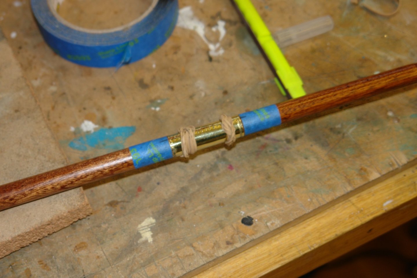
 Thank you Pat but I need to curb my deviant tendencies. I am still working on the lower main and foremasts. Where the gaff saddle bears against the masts the masts are sheathed with brass. I made the sheaths from .004" flat brass sheet. I rolled the sheet using steel rods with the sheet supported on a cork mat. Rubbing the rod repeatedly across the sheet produced the necessary curvature. I then machined up two pieces of aluminium tube to the same diameters as the masts. I then glued the brass sleeves to the tube using CA glue. The sleeves were held in place by elastic bands while the glue dried. The tube was then moved to the mill and mounted in the rotary table. With this set up radial and axial indents were cut to simulate the fixing studs. Heat was then applied to separate the sleeves from the tube. The tubes were given a polish and attached to the masts again using CA glue and elastic bands. The positions of the sleeves were marked with tape prior to gluing.

-
I agree it may look like that but the tools are only a means to the end, which is the model. Thank you for your contribution and I will take note in case my obsession deviates in that direction.
-
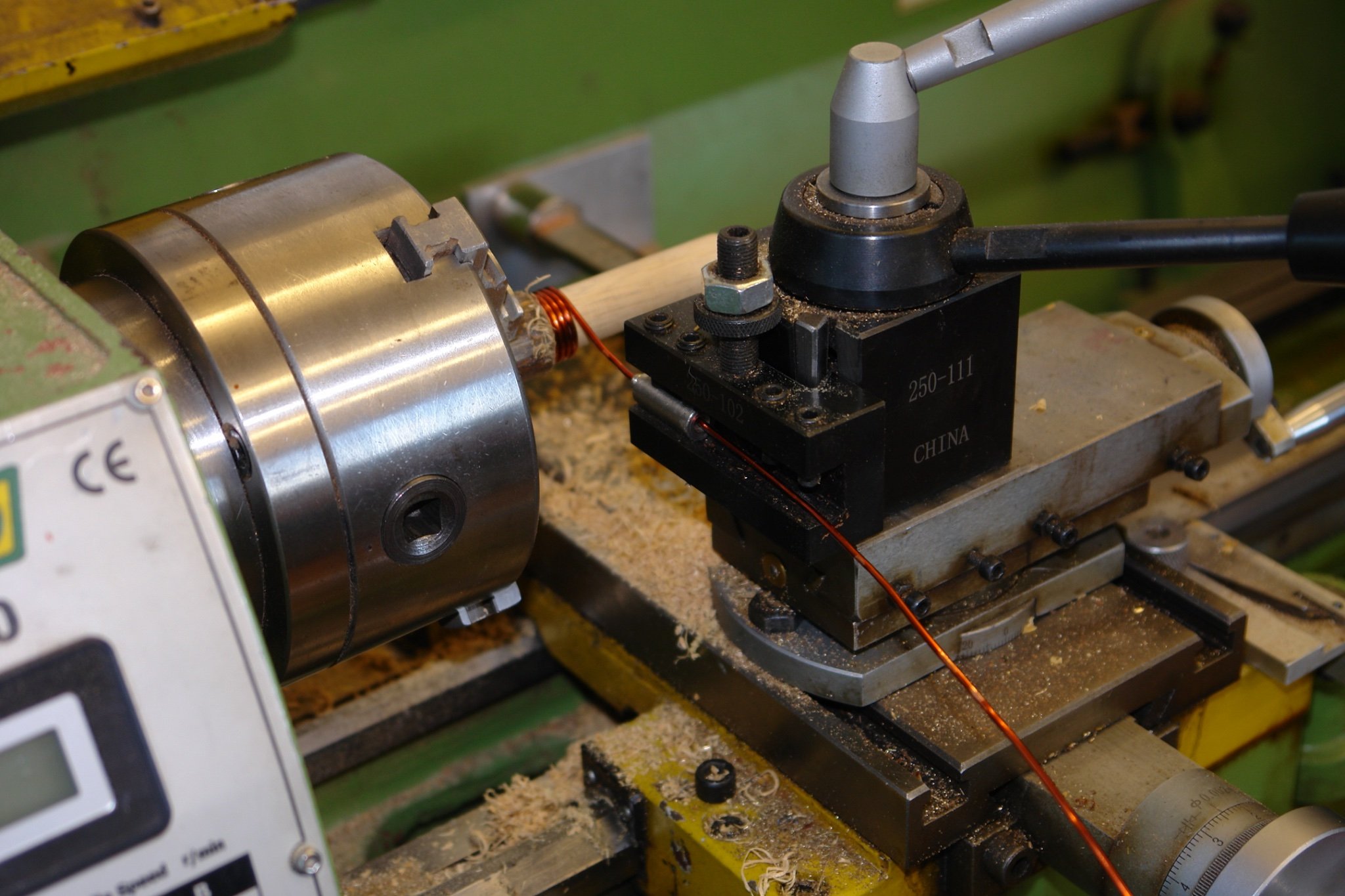
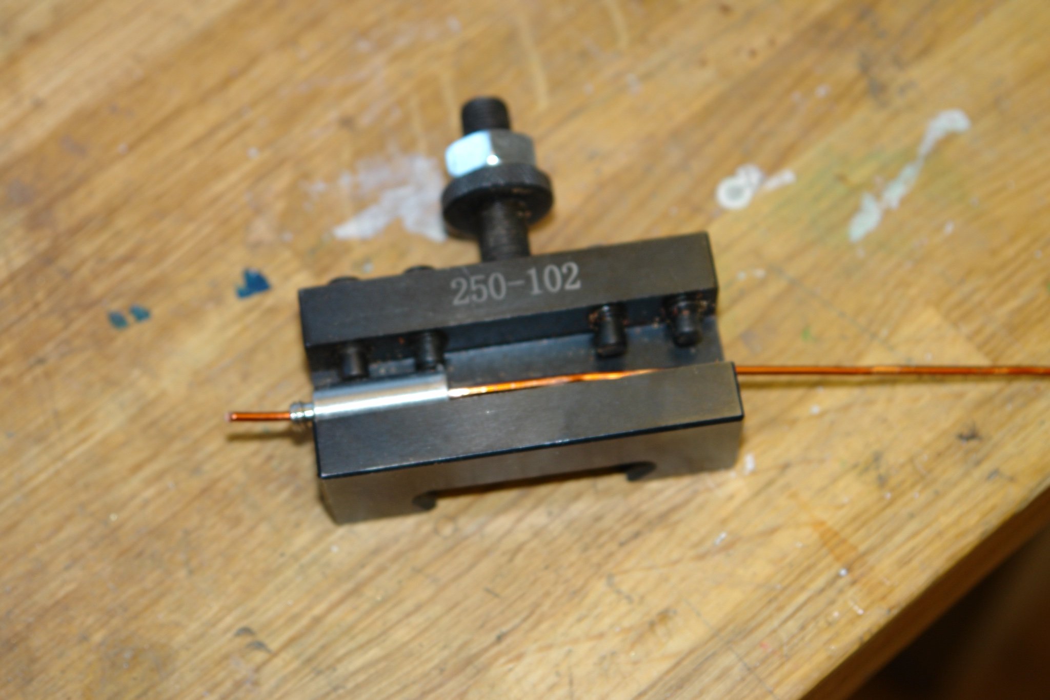
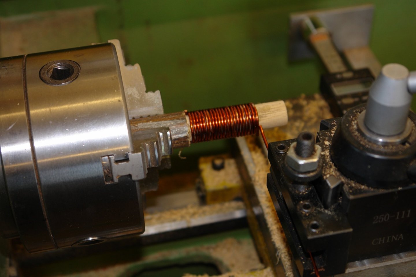
I find the the tension on the wire during winding makes the coils wind very tightly and evenly on the mandrel thus reducing the variability in the finished coil diameter. Its so simple to set up that it sort of makes sense to get the better control while not taking any more time. The set up time was about 15 minutes and the 20+ coils were wound in 20 seconds (lathe speed 60 RPM).
-
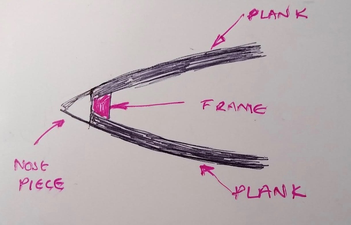
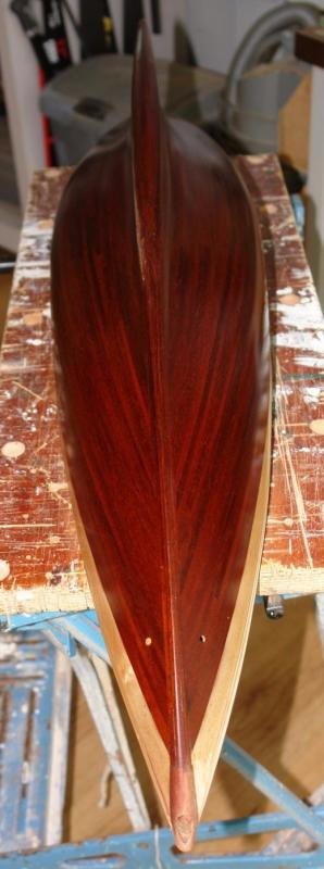
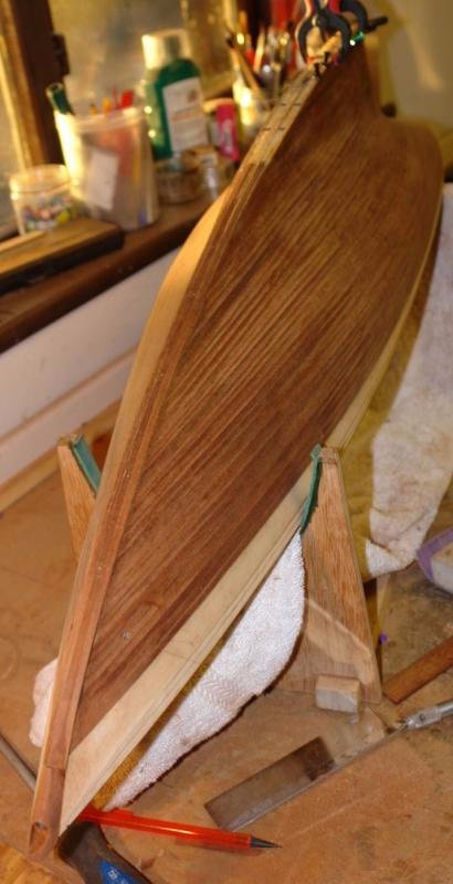
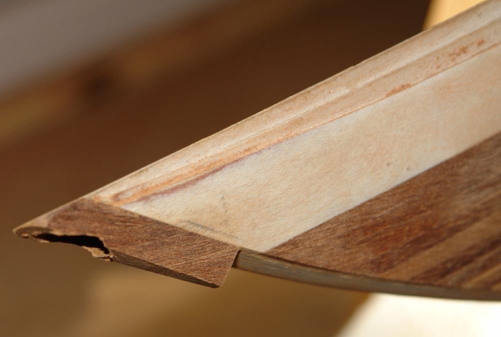
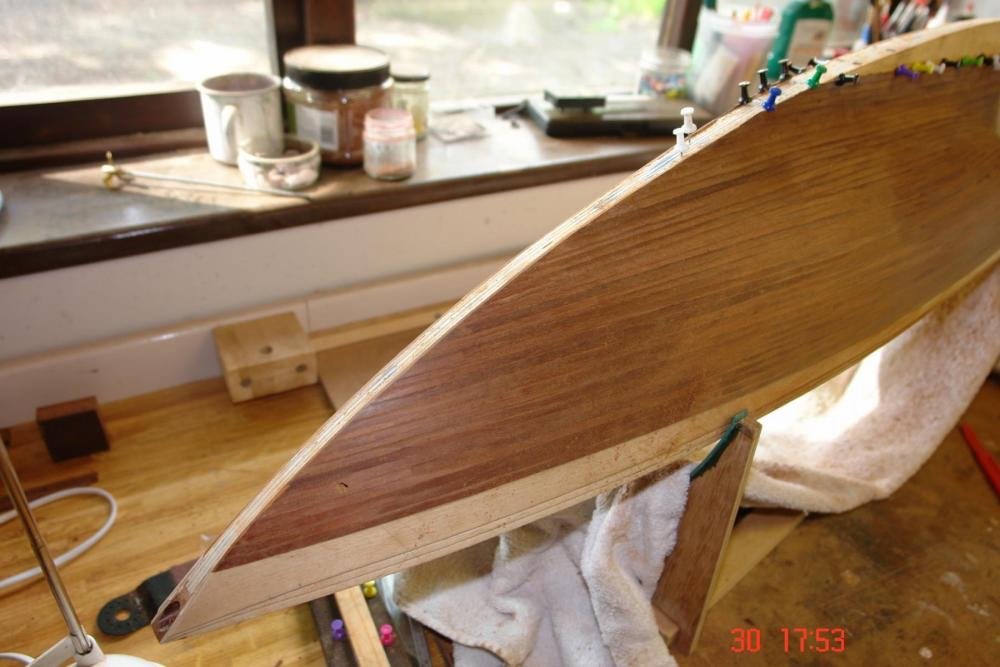
If you are not confident this is a simple alternative:- Install a vertical frame very close to the final bow position. Plank on to this frame and then sand back the plank ends until flush with the frame. Then glue on the nose piece. It is probably easier to glue on a square block of wood and then shape to match the angle of the planks once attached. I quite often do a version of this technique as follows:- Alternatively you could laminate up the bow with the rabbit pre formed as you have done with the keel.
-
Keith - yes and yes. although thankfully sail making will be some time in the new year. Steve - Thank you "old motor winder"! I will give it a try.
-
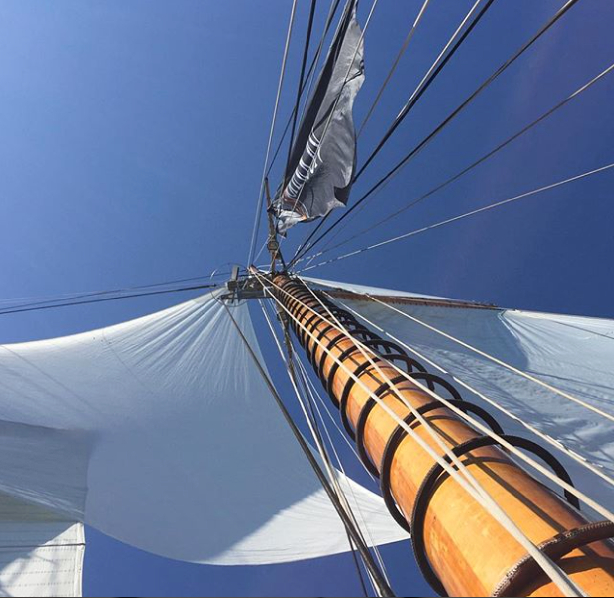
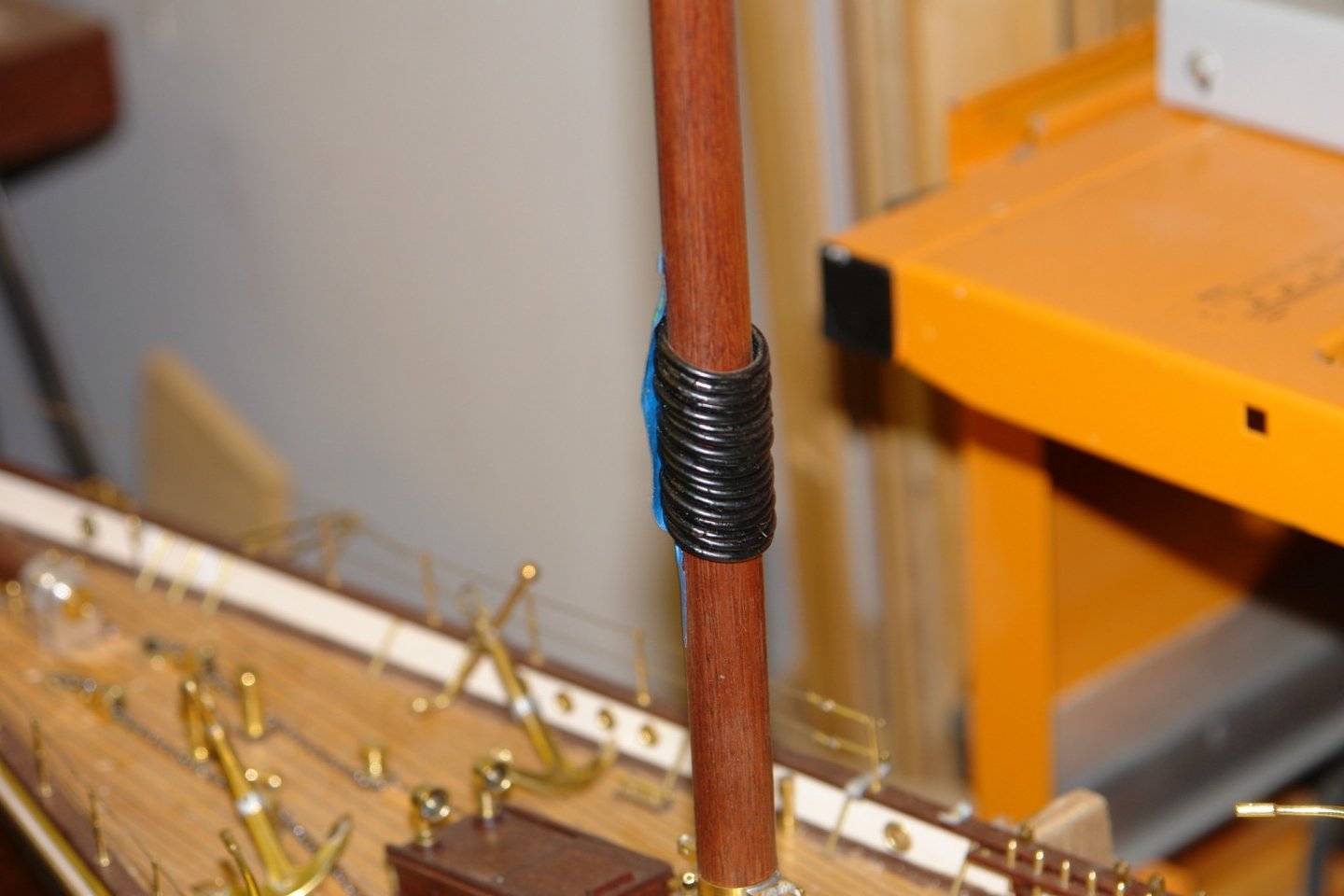
Thank you Gary and FF. and thanks to everyone who has viewed and left a thumbs up. Before I permanently attach the cross tress i need to attach all the bands below the cross tree level. Also I need to make and install the mast hoops. I decided not to go down the steamed and bent wood approach. At model scale I think they are too bulky if sufficiently strong and too flimsy if correctly sized. Various photographs of Germania show the hoops as almost back while others show them as a medium brown. The hoops are leather covered and I think the difference in colour is age / lighting related, anyway I prefer them darker. The hoops need to be about 20% larger than the masts and as the masts differ in diameter this means two sizes of hoop. Circa .68" and .73" diameter respectively. I decided to make the hoops out of copper wire (actually the secondary winding of a dead battery charger). This was about the right diameter, I decided to use the standard lathe spring making method to wind the wire. In this method the wire is wound on to a mandrel with the lathe set up for screw cutting. The pitch is set to diameter of the wire. The wire is drawn on to the mandrel through a guide held in the tool post. This is close fitted to the wire and provides a fair degree of friction to ensure that the coils are wound tightly. Because the coils spring away from the mandrel at the and of the winding process the mandrel needs to undersized relative to desired hoop diameter. The mandrel size was deduced through trial and error. Keeping clear of the wire during the winding operation is fairly important if you value your fingers. The second attempt wasn't as good but adequate for my purposes. I then cut along the axis to create individual hoops which were soldered at the joint and painted.


-
If i am understanding you correctly you are thinking about dampening the keel as a precursor to applying pressure to increase the curvature. Given you have laminated the keel with waterproof wood glue i don't think dampening will have an adverse effect. In my experience once wood is laminated imposing further curvature is difficult as the wood resists any attempt to induce further bending. However here in lies the pleasure in ship modelling, all of us come across new situations and new challenges all of the time and improvising solutions is a big part of the stimulation and fun. If you have an idea of how to correct a problem give it a go and maybe the rest of us can learn from it.
-
Not quite sure how I missed this build until now but it was a pleasure catching up. I think some of the build ideas are quite inspired and i particularly liked the "bow" for fairing the frames, the clamping of the frame laminations and the cutting of the hull planks. Everything is up to the usual high build standard. Well done.
- 153 replies
-
- 3
-

-
- Ancre
- Bruno Orsel
- (and 2 more)
-
The madness of the model shipwright is amply demonstrated. lovely work Keith but it boarders on masochism.
-
A remarkable amount of plan detail available given the age of the ship Phil. It all looks rather exciting. I wait the build with anticipation.
-
Very nicely done, always a tricky job.
-
Cap San Diego by mikegr - 1/160
KeithAug replied to mikegr's topic in - Build logs for subjects built 1901 - Present Day
I am pleased you are having another go. She is a very handsome vessel and deserves to be modelled. I remember my first model had plenty of car body filler in the hull. -
A nice little project which I look forward to seeing develop.
-
Eberhard - Try using actual size photographs. or console yourself that they would have looked much worse under a microscope. No one will ever notice.
-
I don't really have that sort of detail but my expectation is that the crosstrees would be rigidly attached to the mast. I will glue the band to the mast so on the model the crosstrees will be rigidly attached.
-
The fit you are getting is truly amazing Richard, and your build speed is very impressive.
- 454 replies
-
- 2
-
-
- Union Steamship Company
- Stepcraft 840
- (and 3 more)
-
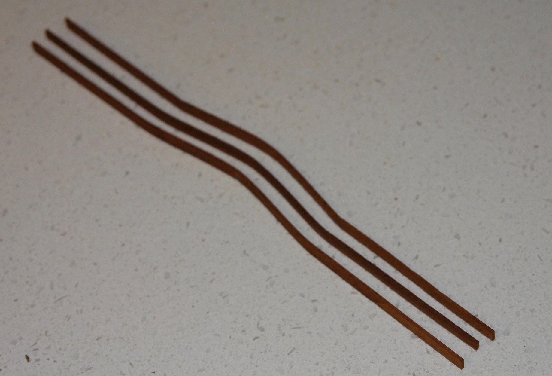
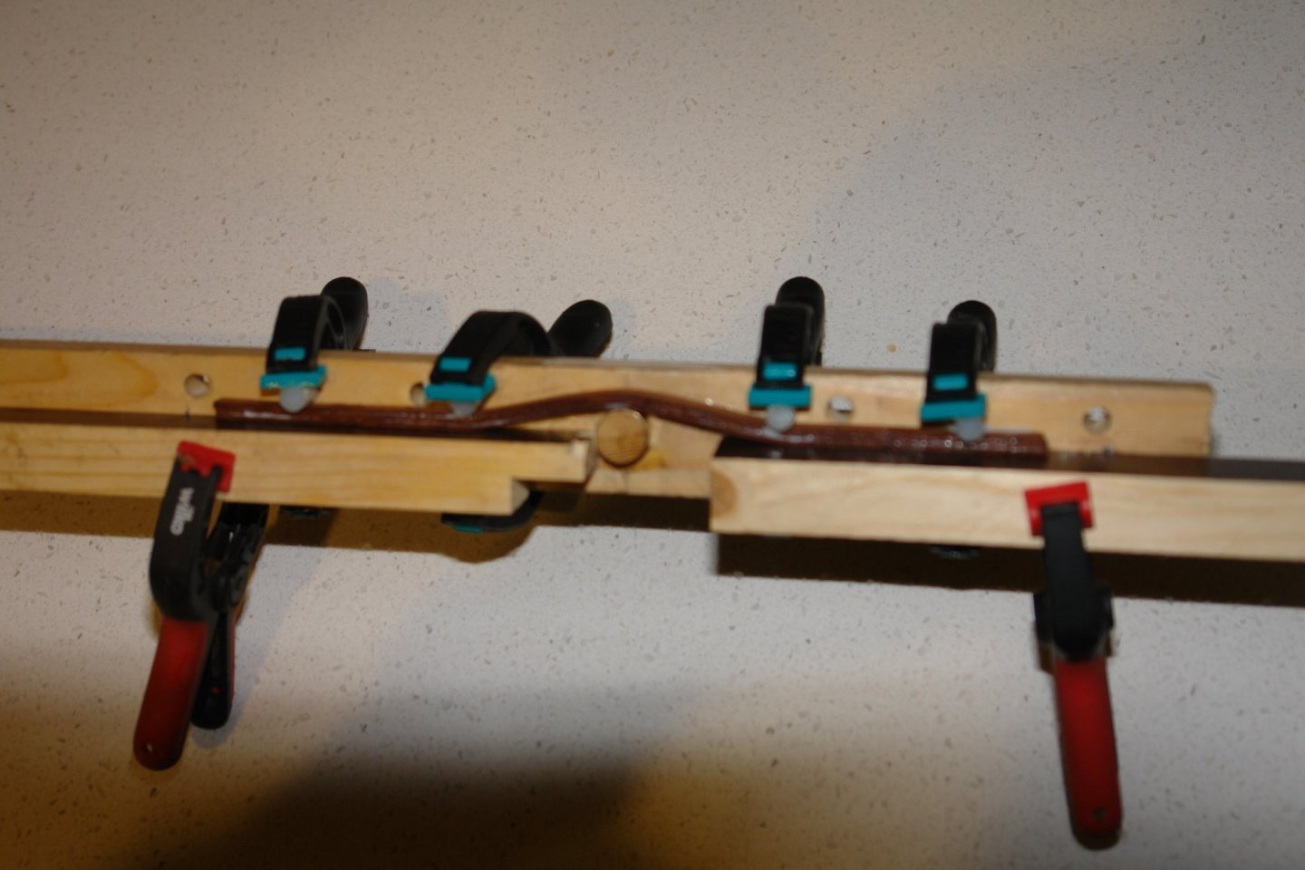
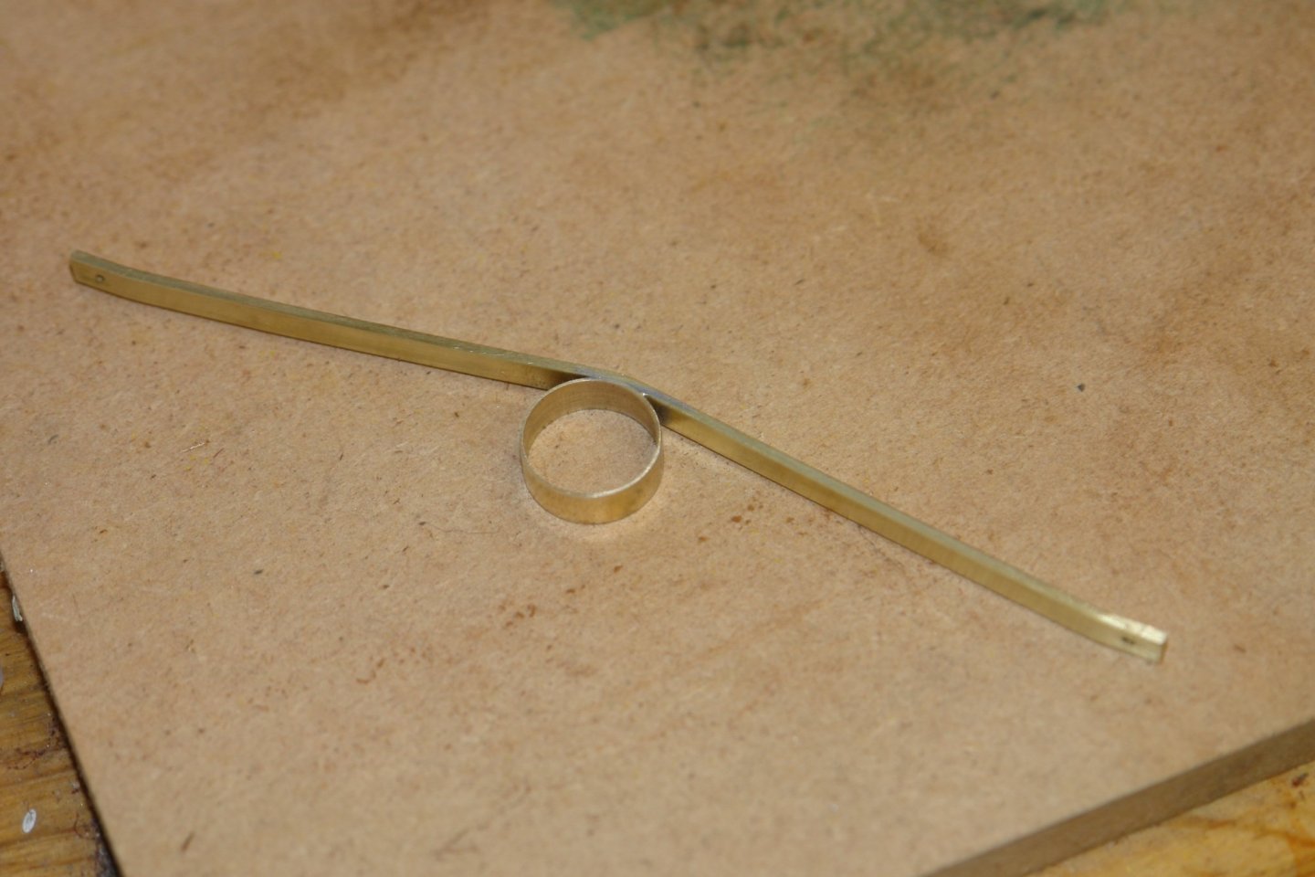
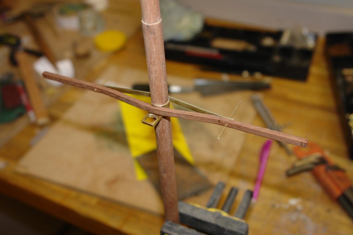
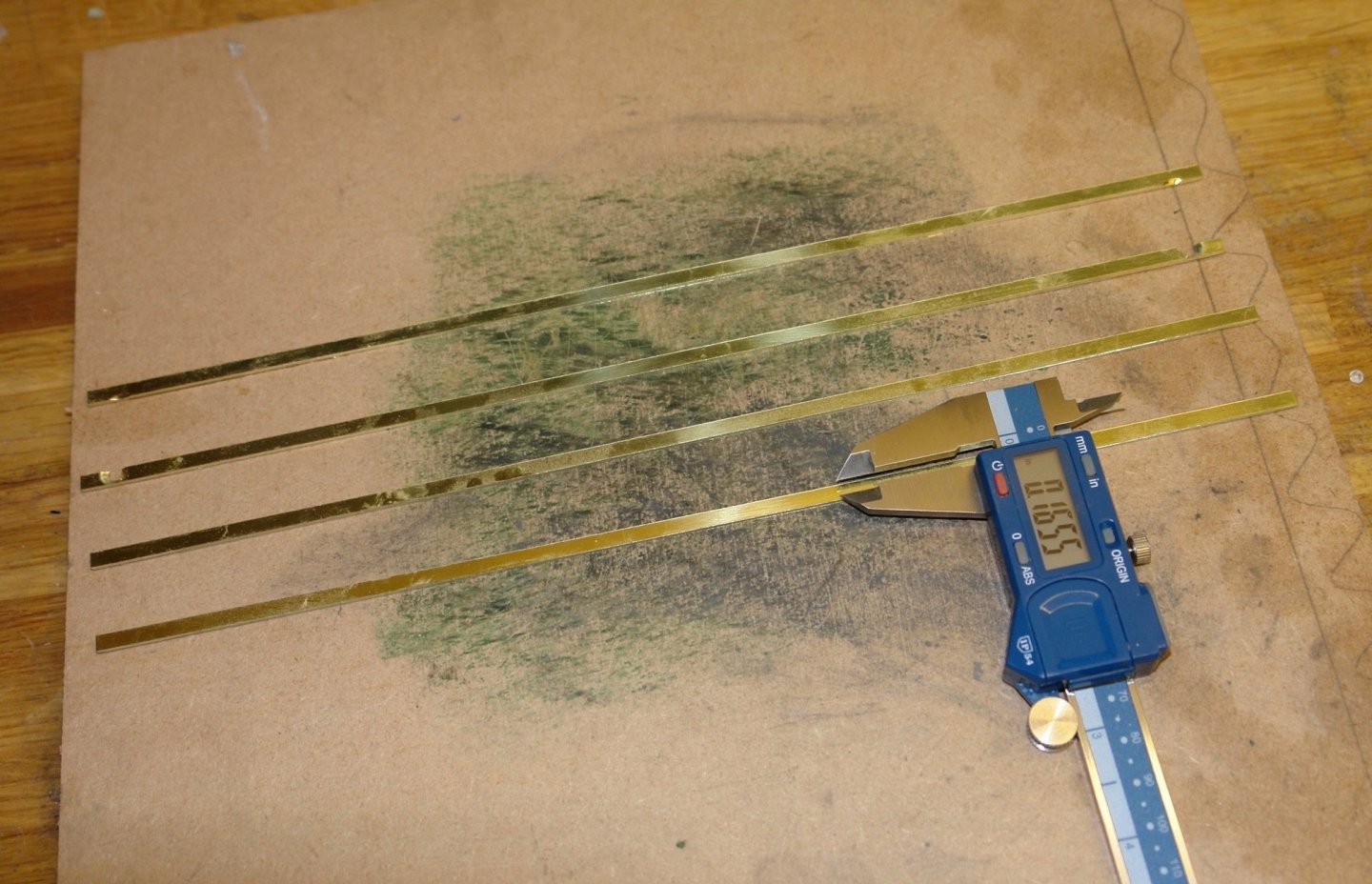
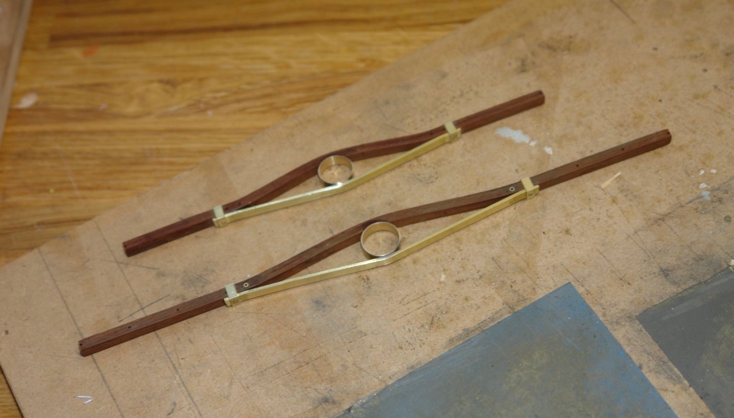
Thank you Keith. I have spent couple of day making the crosstrees. I needed some .165" wide brass strips. I had bought a few brass door "finger" plates a few years ago when they were being sold off at a huge discount. From these I slit off a number of strips on the mill. The cross section of the crosstrees is .2" high by .160" wide. To ease bending I decided to laminate them from 3 strips of .2" x .053" mahogany. I soaked the strips in boiling water for 5 minutes before clamping them in the bending jig and leaving overnight. I then used the bending jig to clamp the laminations while glueing. . I then cut and bent the bracing straps and soldered them to the mast bands. Various holes were drilled through the crosstrees to allow the shrouds to pass through and various instruments and fittings to be mounted. the holes for the shrouds were strengthened with brass tube. I checked the look by doing a temporary install on the mast. The finished article:-


-
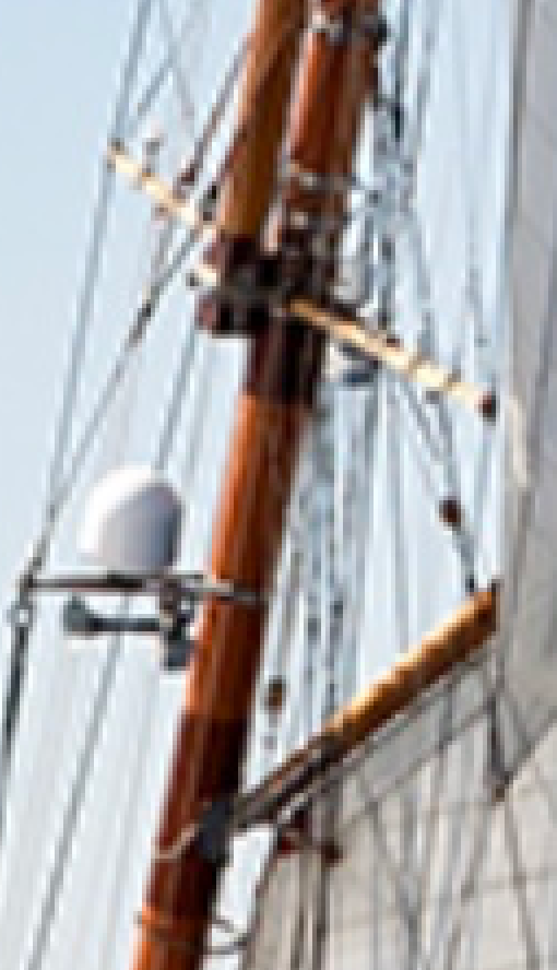
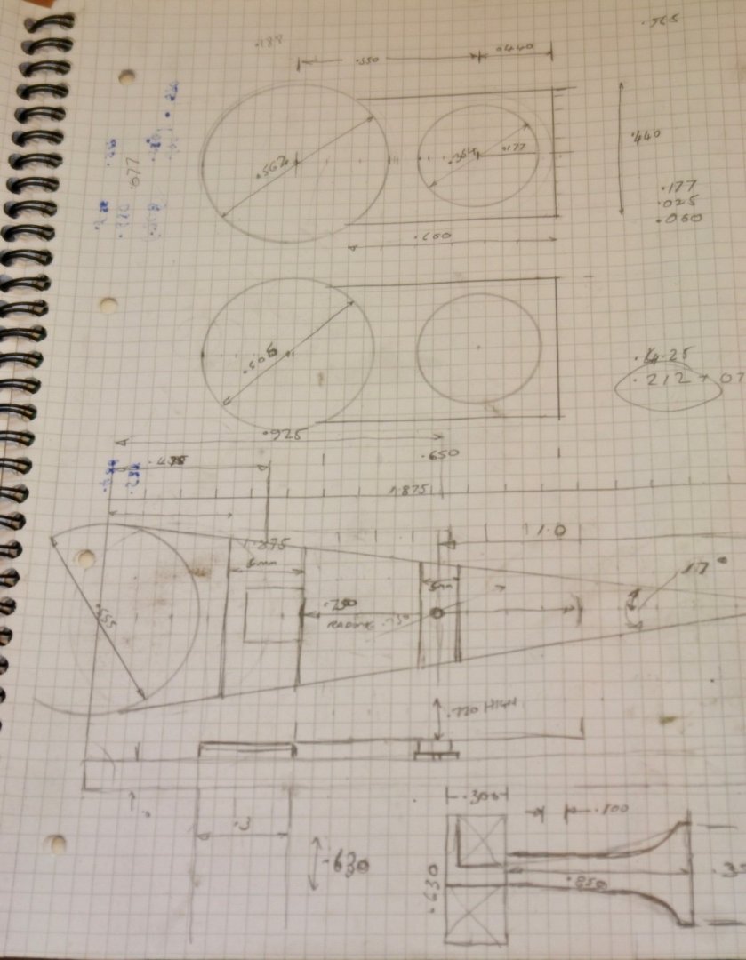
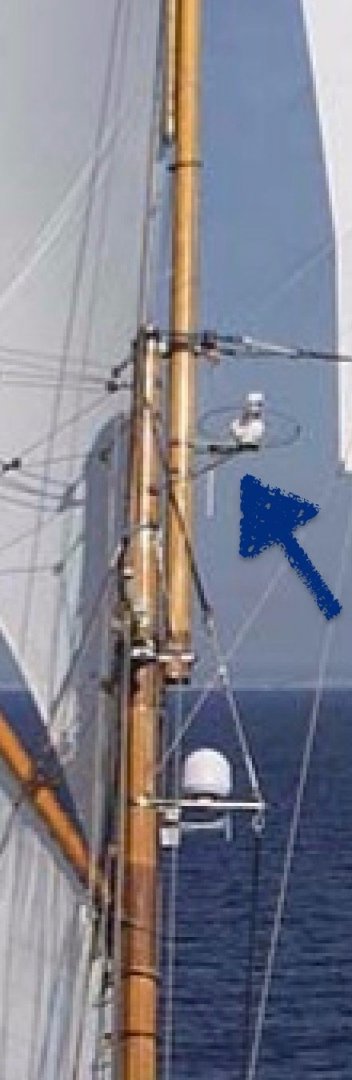
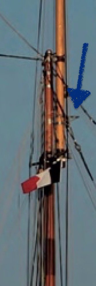
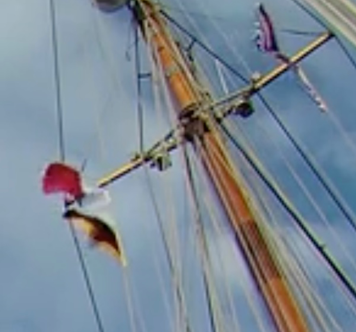
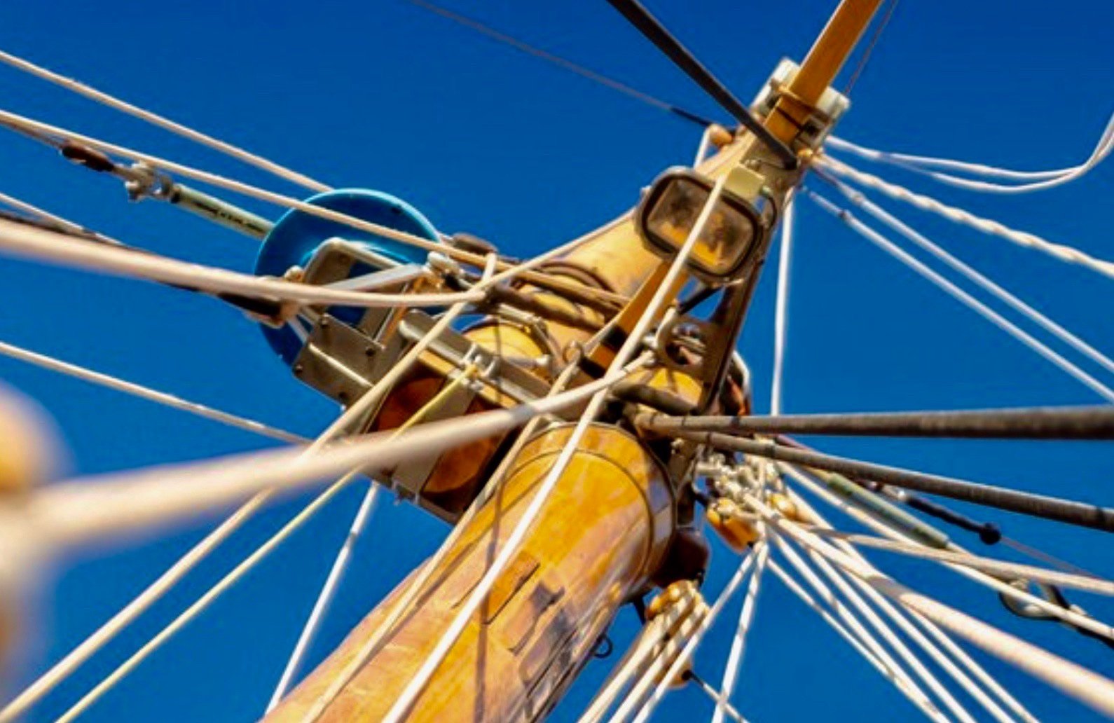
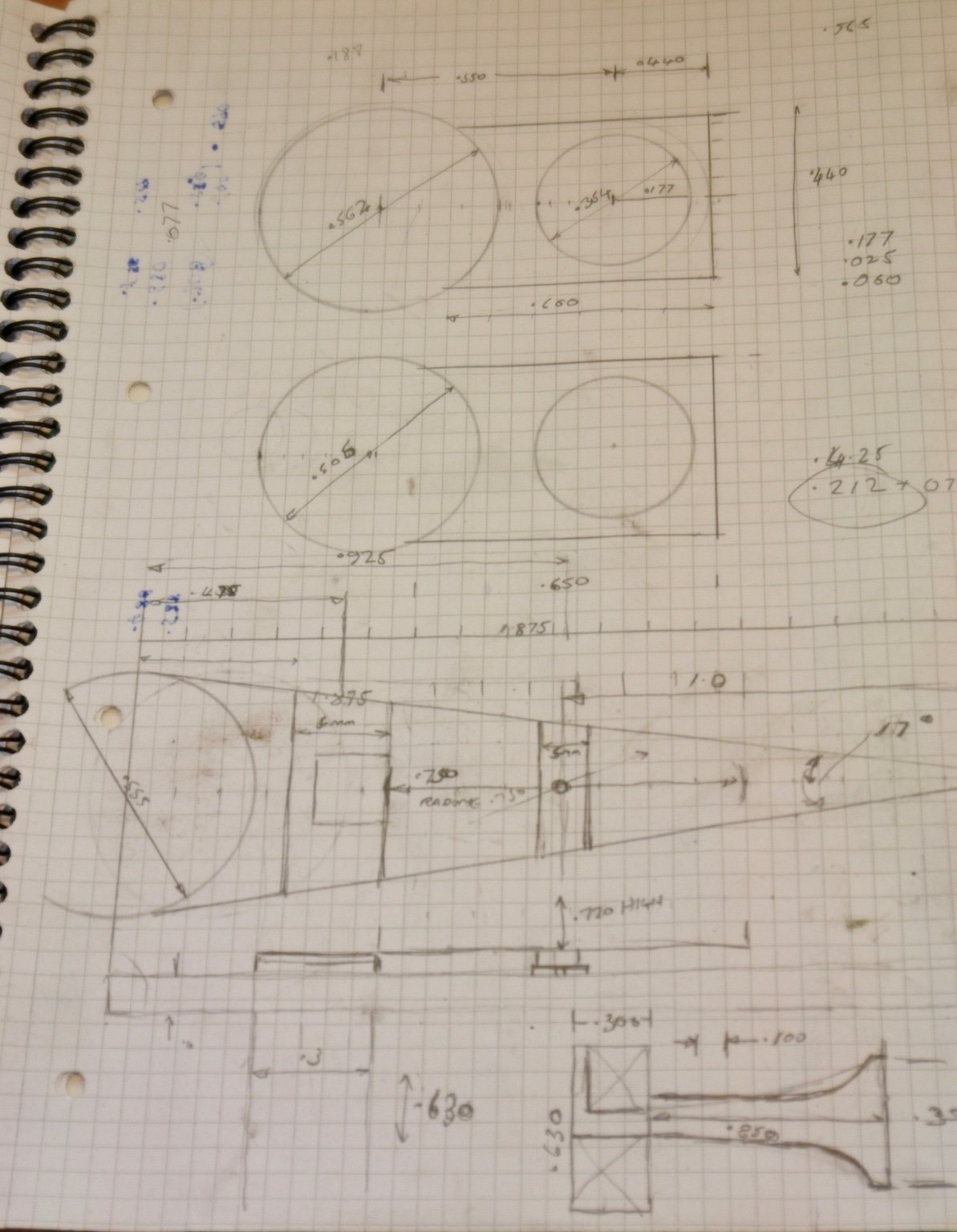
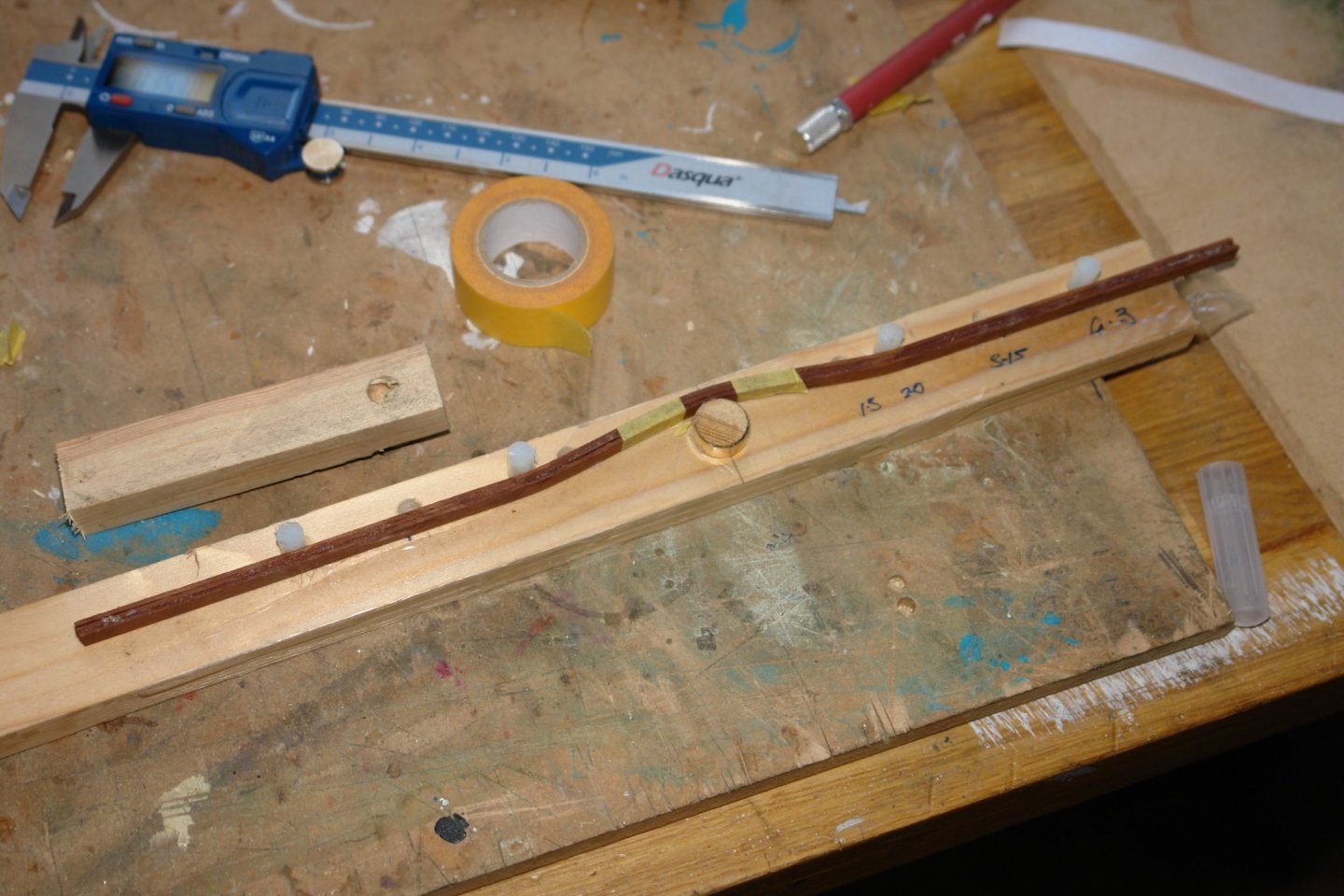
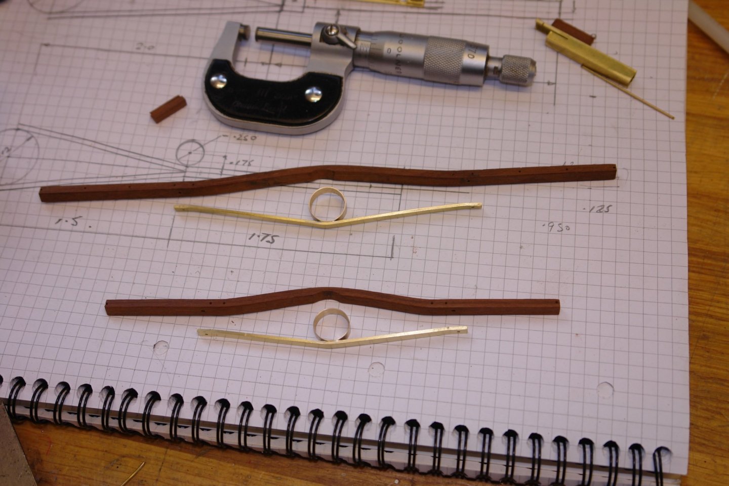
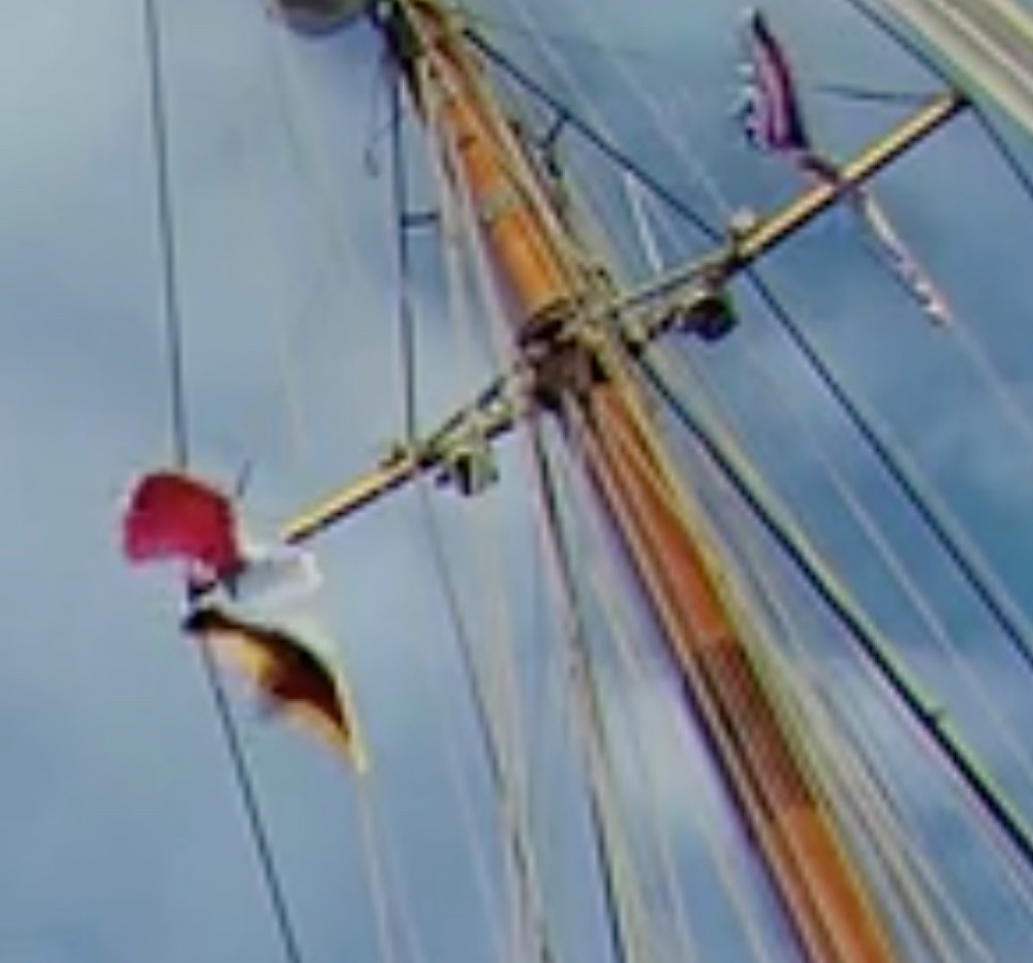
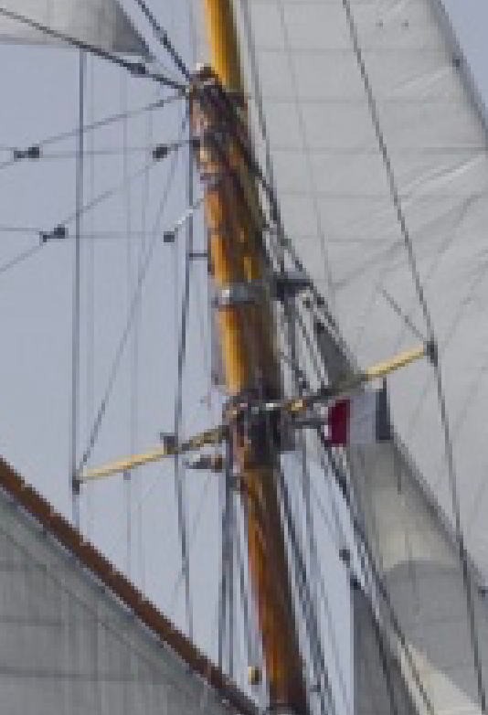
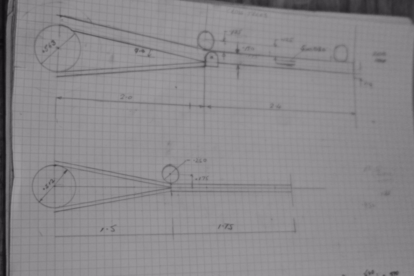
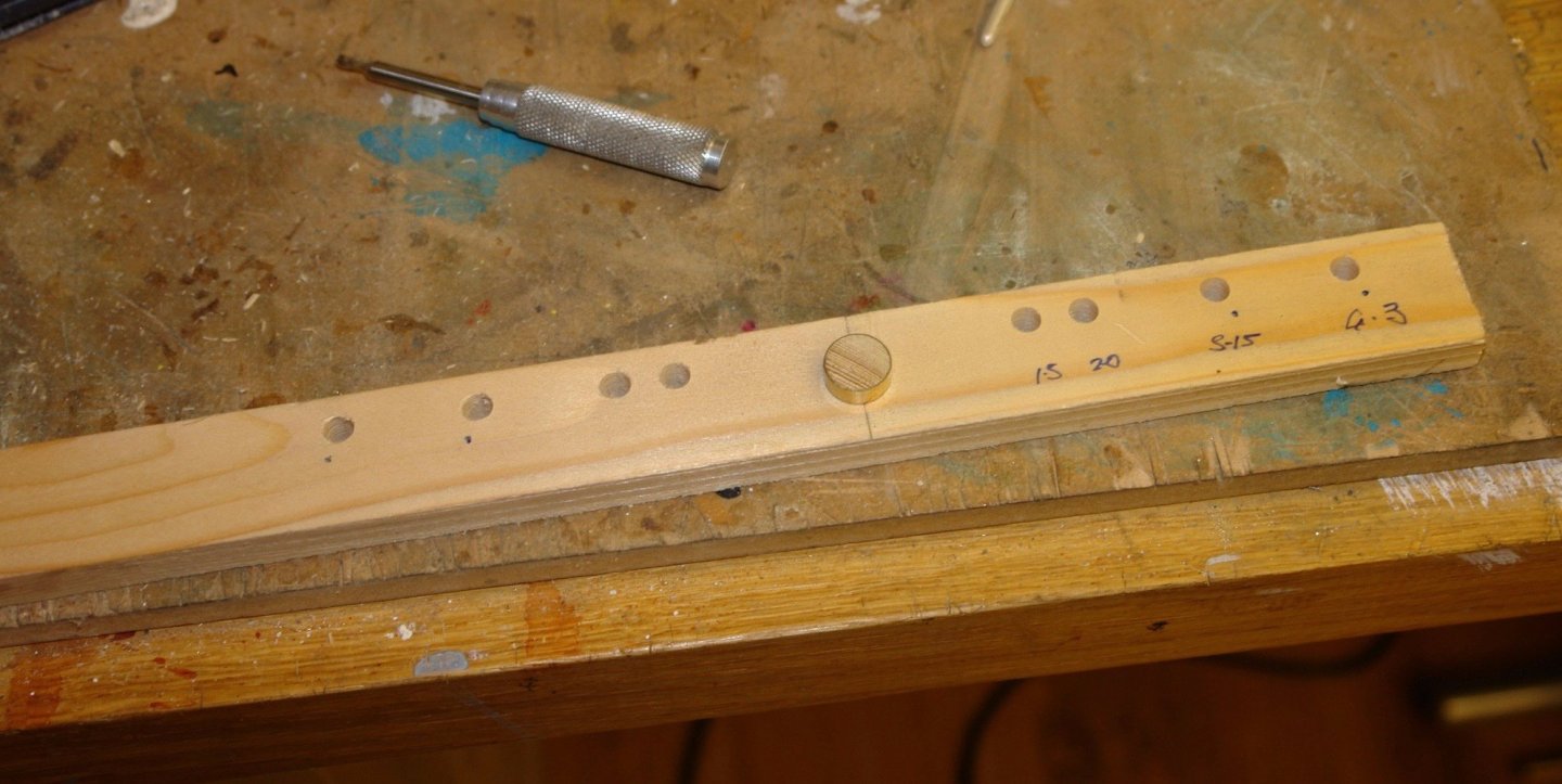
The next job is the crosstrees but these come with a few challenges. Firstly it isn't proving easy to get their correct span. Photos taken from the deck suffer from parallax error and all the photos taken off-board Germania are either side or three-quarter shots. I decided the best approach is to make the spans equal to the beam at the fore mast and main mast positions. The second problem is that the photos of the cross trees are proving difficult to interpret and I can convince myself that they are constructed from metal or wood and are both rectangular and round in section. Here are the better photos:- I think I am going to go with my interpretation of the third photo which is a rectangular wooden spar shaped around the front of the mast and secured with a metal brace to the rear. I did a sketch of my interpretation. The top sketch is of the main crosstree. this has a span of 8.8". The lower sketch is of the fore crosstree and is only done to record the relevant dimensions. In this case the span is 6.5" Having decided on a plan I made myself a jig to assist bending and assembly. The hole positions match the circles drawn on the sketch. The jig allows both crosstrees to be made. The dowel up-stand is the diameter of the mast and is replaceable as i need 2 because of the different diameters of the main and fore masts. The holes towards the top edge take nylon pins, these will locate the bending points. Different holes will be used for the two crosstrees. Hopefully this will make more sense when I do my next post (assuming that it works!!!).

-
Shaun Nice woodworking skills. You must have been working with wood for some time???
-
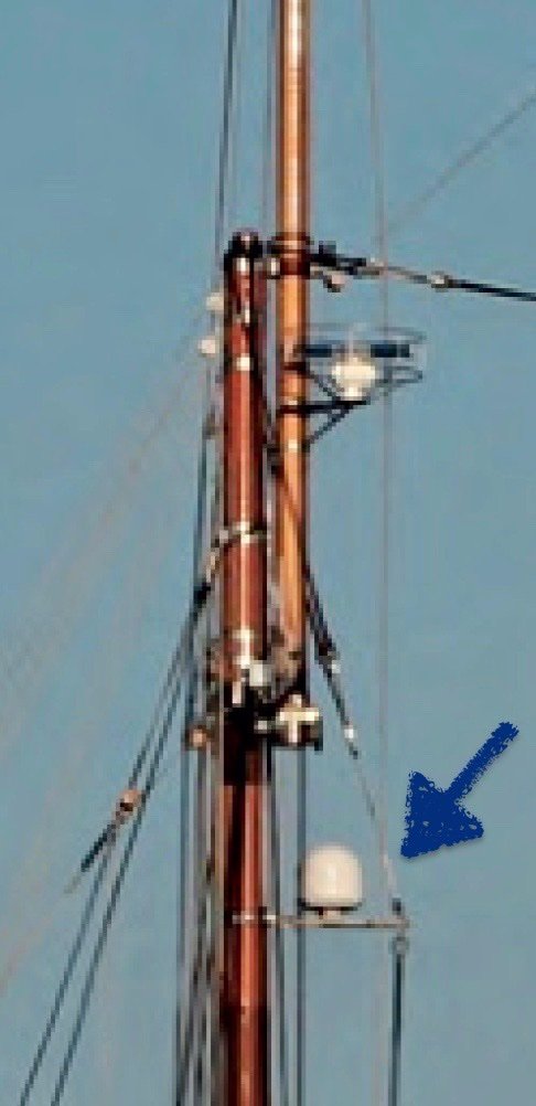
Innisfree - Thank you for commenting on my build. Your suggestion re the radar prompted me to check web images and as you say the dome may well house a weather radar. Mark / Pat - thanks to both of you for your thoughts.
-
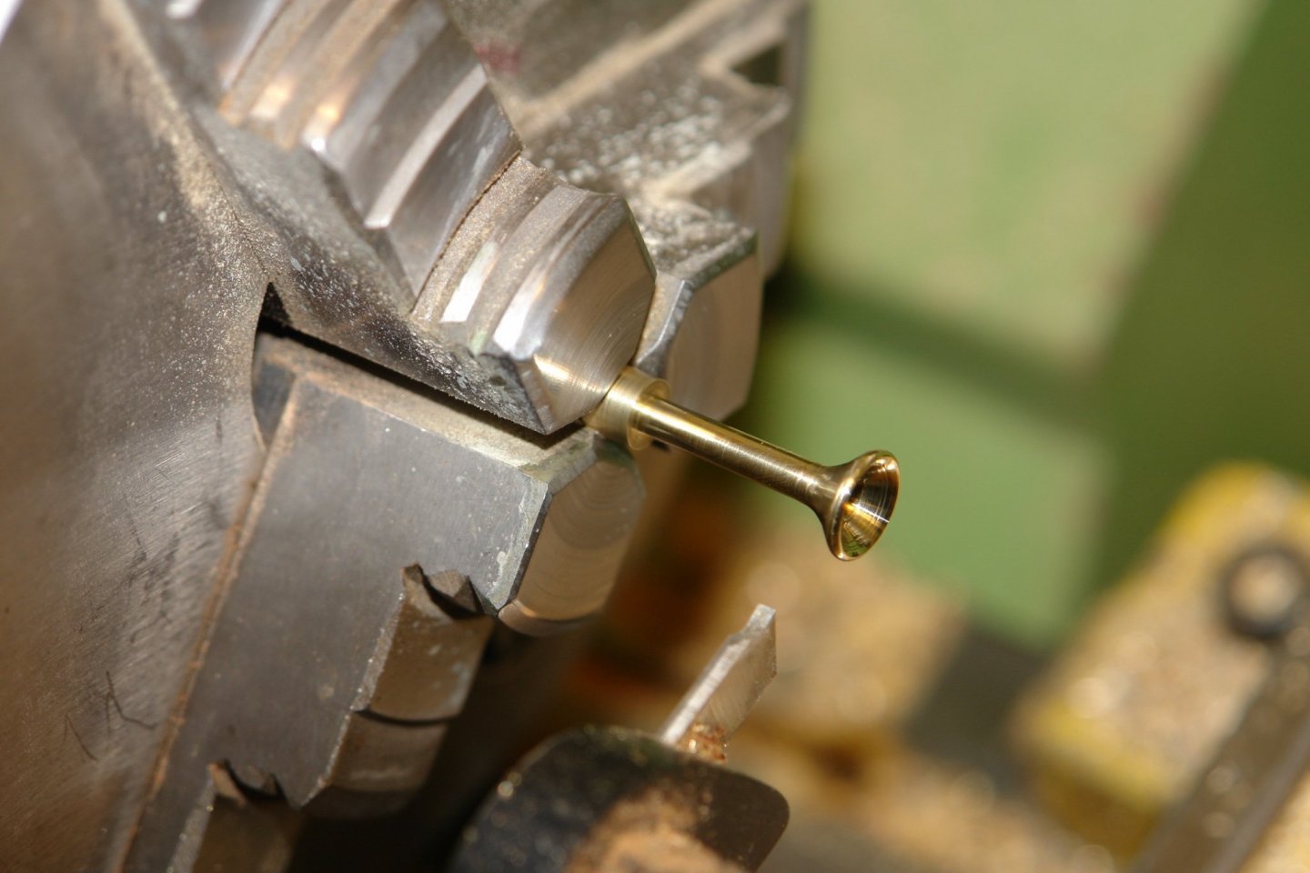
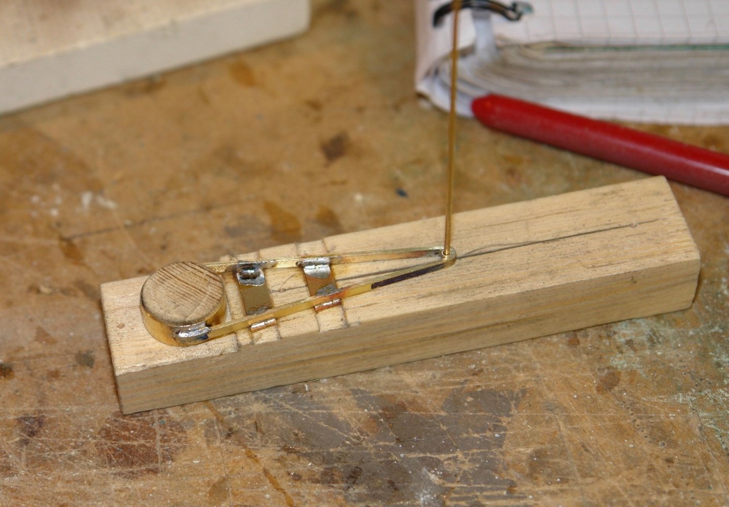
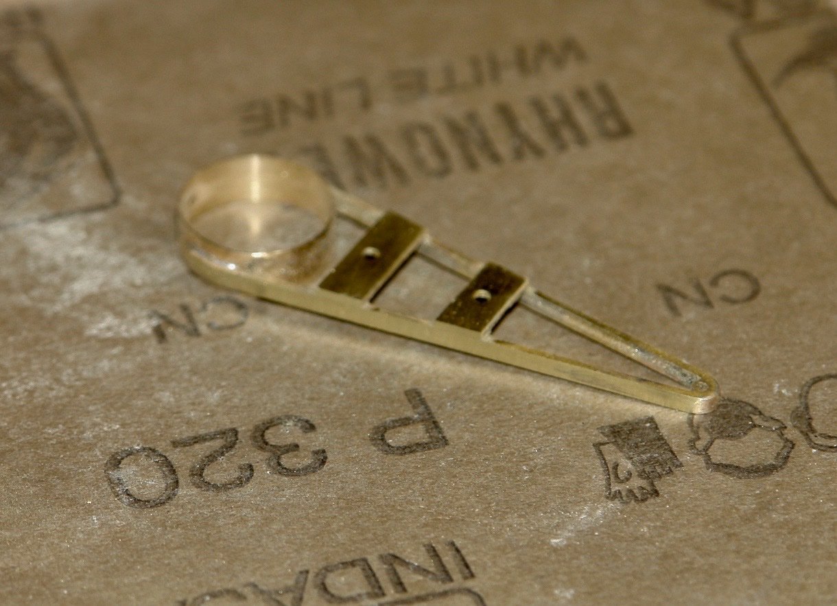
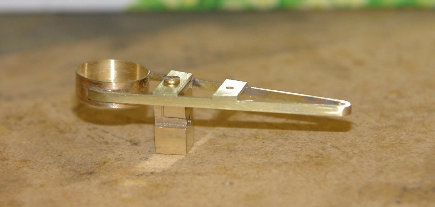
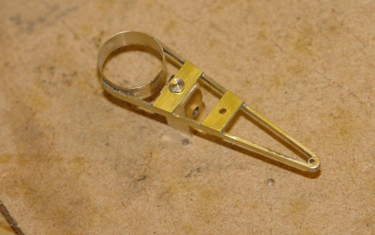
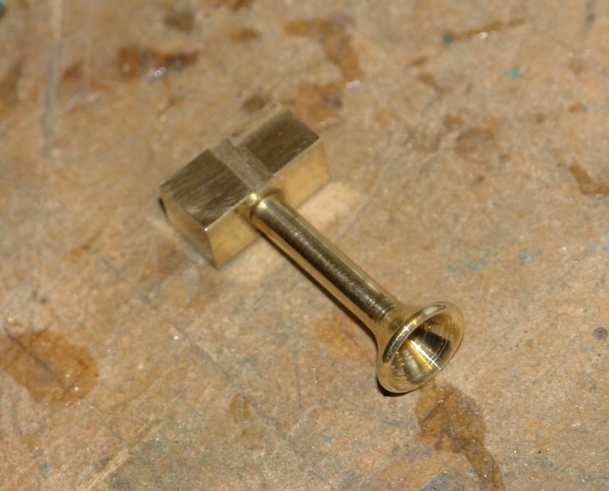
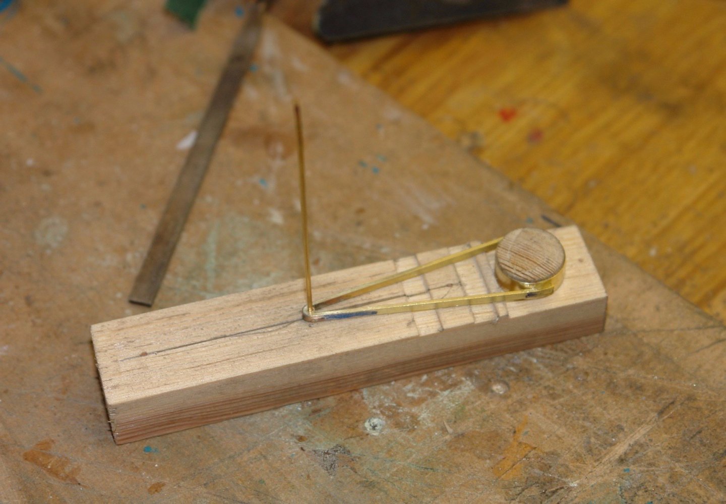
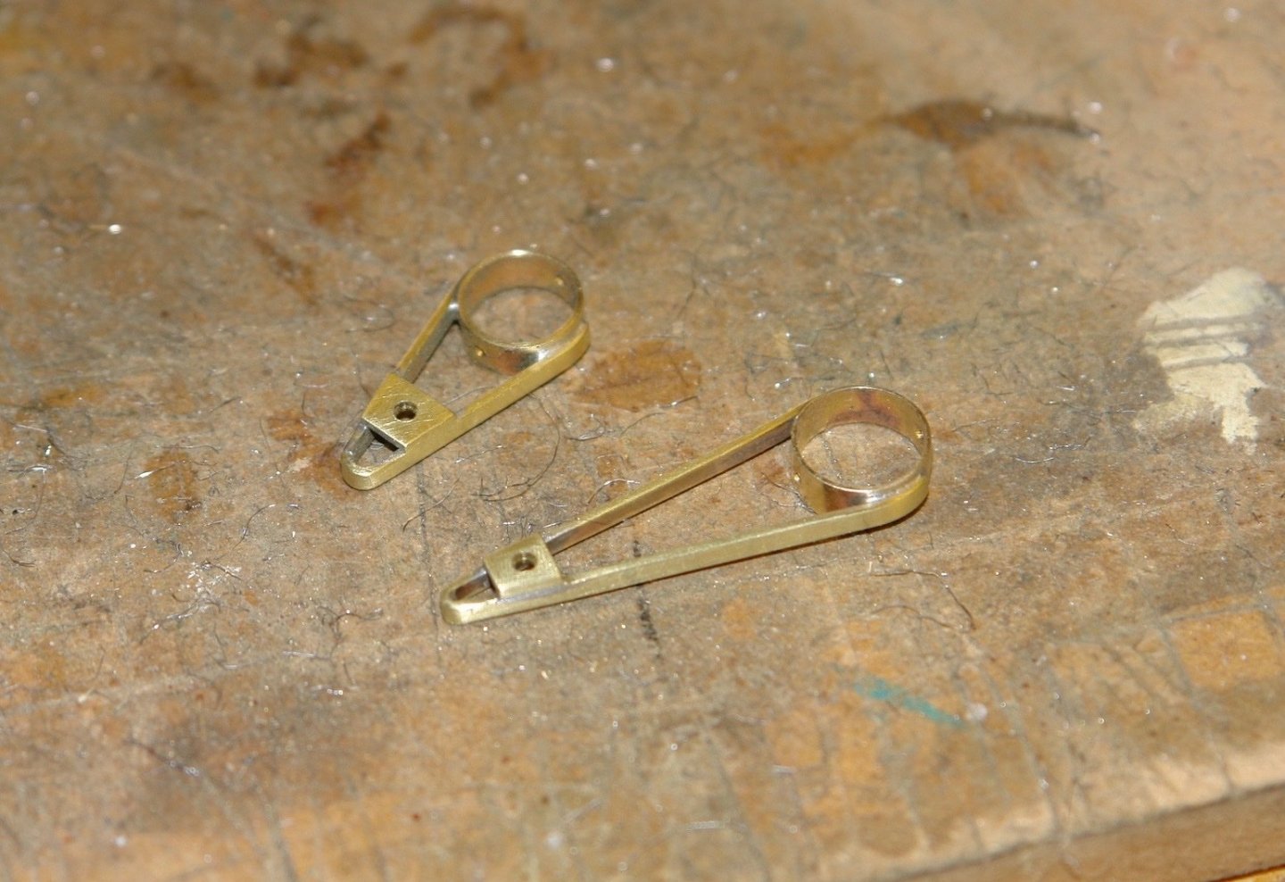
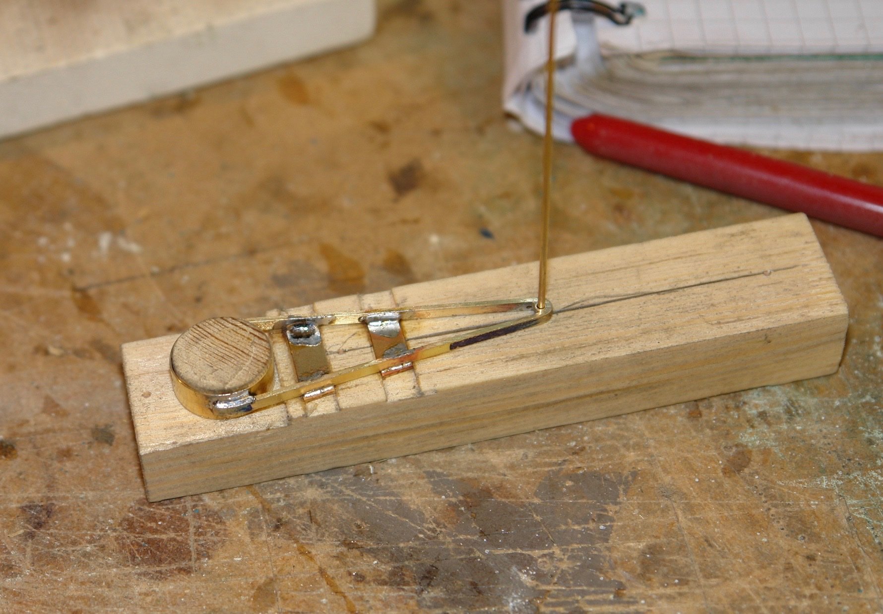
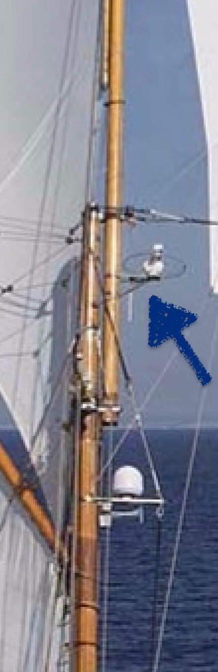
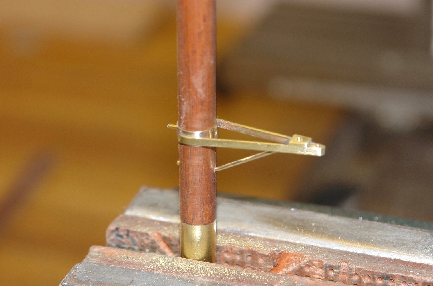
More mast fittings but at least these are a bit more interesting. On the main mast are two supports for mounting the main radar and what I glass is a satellite communications dome. On the fore mast is a further support on which is mounted what appears to be a small radar. Why two radars? Starting with the bracket for the communications dome ( which also carries the fog horn and the main mast fore brace). The fog horn mount only features in one of the pictures but I like it so will go with that option. I started with a very basic sketch, i didn't feel I needed to draw all the detail so I only committed the basic dimensions to paper. I like soldering jigs because they make the work easier and more accurate. On this occasion the jig was machined from a scrap of wood The dowel locates the previously made mast hoop and the cross slots locate the flanges for mounting the dome and the horn. A brass pin at the end locates the tube for the mast brace. The components were soft soldered together. The bracket cleaned up well. The horn was machined on the lathe with a bit of double handed turning to create to curve, The motor for the horn is carried in a rectangular box at its rear end. This has a bit of profiling and was made on the mill. The bracket for the main mast radar is less complicated but was made in a similar manner. The fore mast radar bracket was similar - but shorter. Thats all for today folks.