KeithAug
-
Posts
3,986 -
Joined
-
Last visited
Content Type
Profiles
Forums
Gallery
Events
Everything posted by KeithAug
-
 Yes Gary, but i can't help thinking that I should be doing something for society. However i will probably just do more modelling. Tank you Chris and Veszett
 -
Keith - unfortunately the cube root is a much better way of considering the relativity between the original and my creation. So that means i should charge 1/(36x36x36) or 1/46656 of the sale price = 107. For 4000 hours that means .026 per hour. I think I am undervalued.
-
Keith Much too many, fortunately i don't count because if i did would be depressed that I was wasting my golden years. Total elapsed build time is just coming up to 3 years. Preliminary research started about half a year before that. However I take comfort from knowing that many builds are much longer than mine -------- I may be mad but not as mad as some of you.
-
That sounds interesting. I look forward to seeing how it goes.
- 454 replies
-
- 1
-

-
- Union Steamship Company
- Stepcraft 840
- (and 3 more)
-
An interesting build which I will be pleased to follow.
-
Neat idea - must remember that one. Very clean build - impressive.
-
Thank you Bruce - I looked with interest but unfortunately it is a bit to expensive for me. Interesting thought Mark.
-
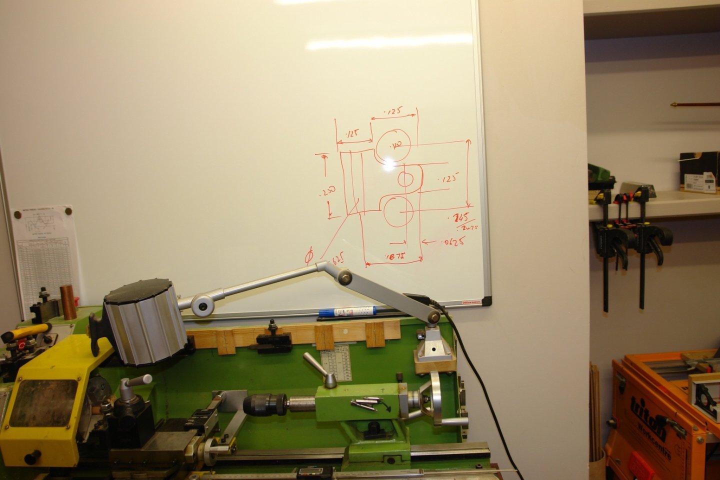
Mark, The photos I have are only part views but the sketch below hopefully shows what I mean. Eberhard, Keith, John, Druxey, Pat, Thank you all for your comments - you are too kind. I am pleased to report the weather has turned milder - 15c (59f) in the workshop today - second jumper postponed.
-
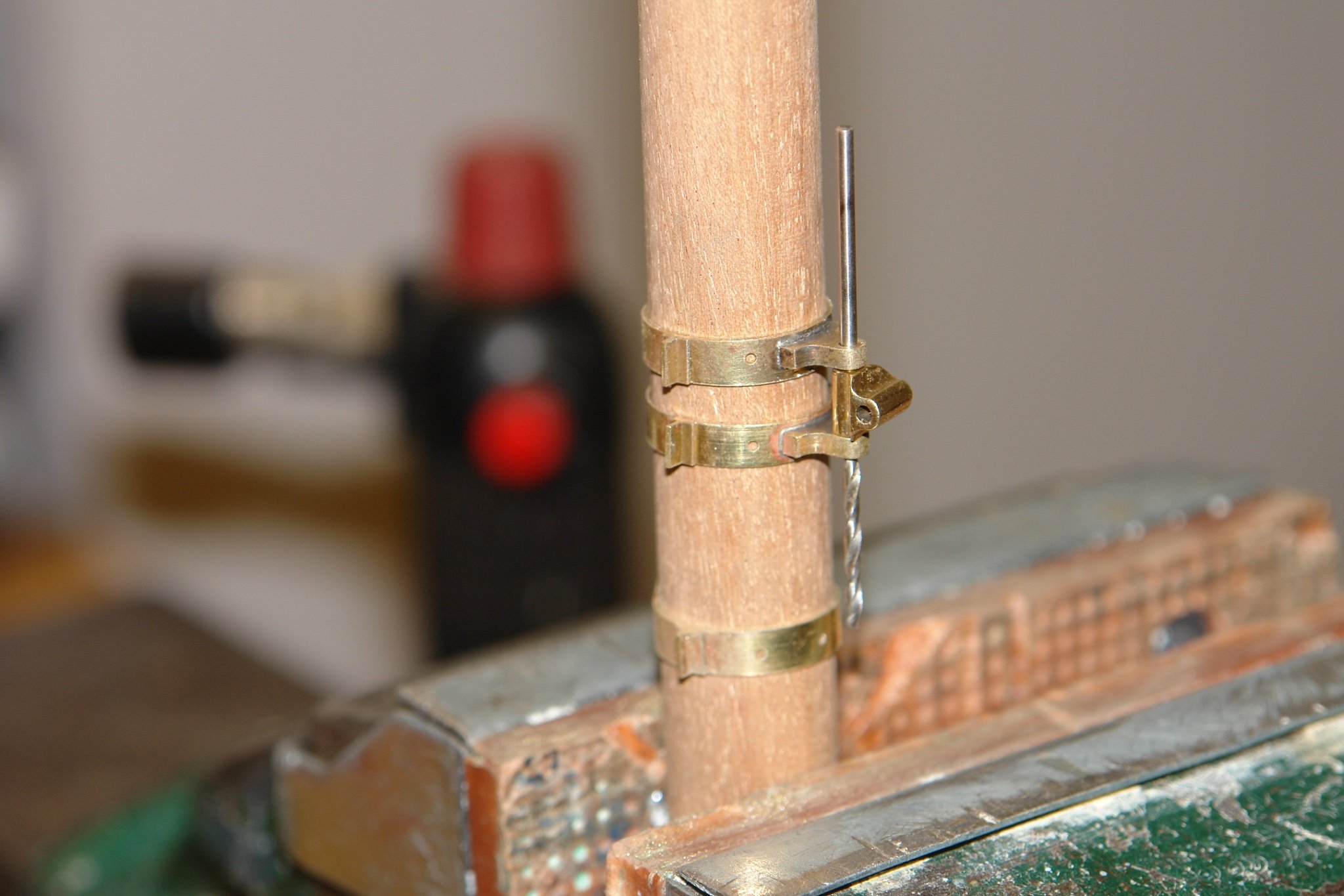
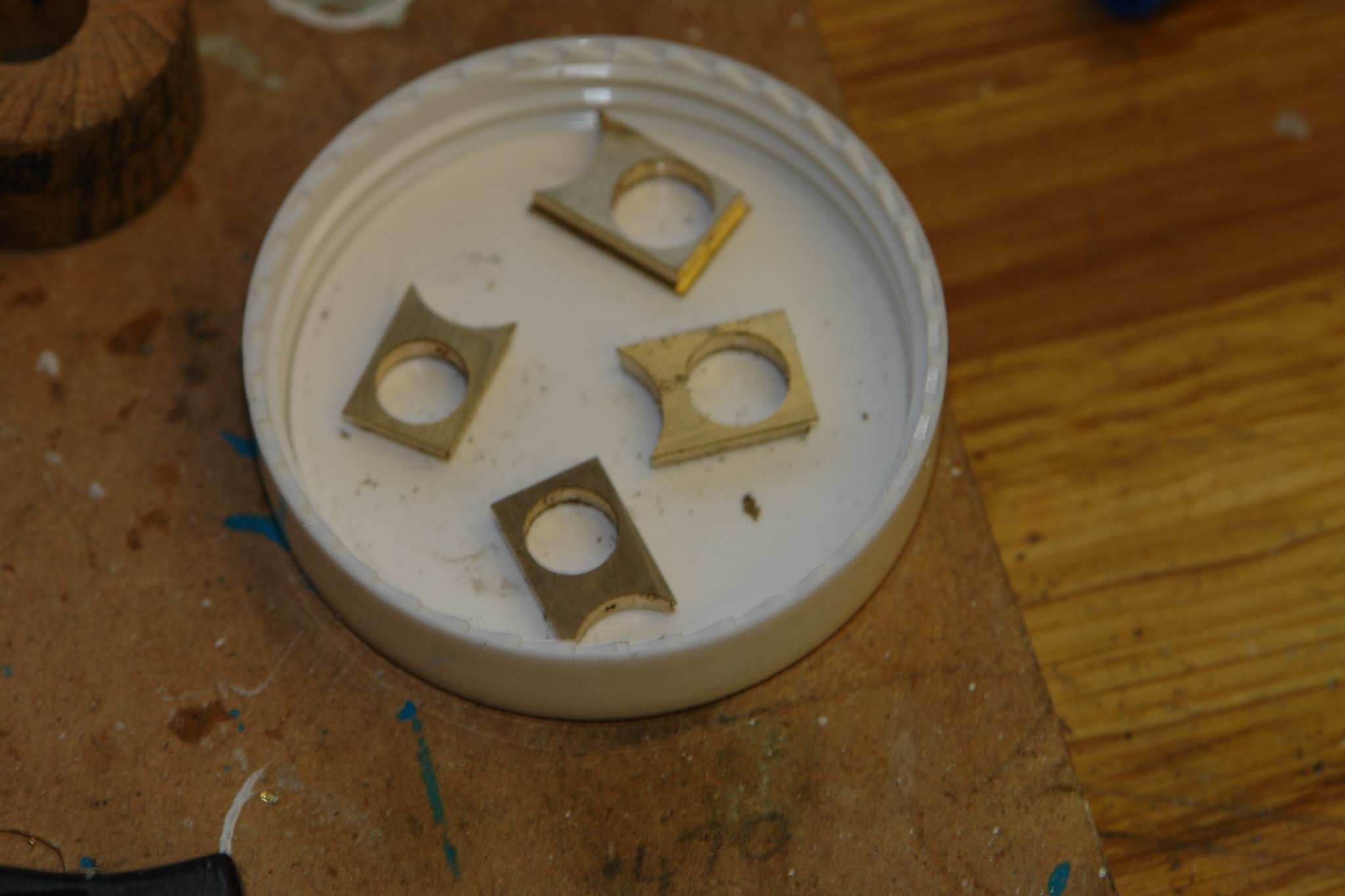
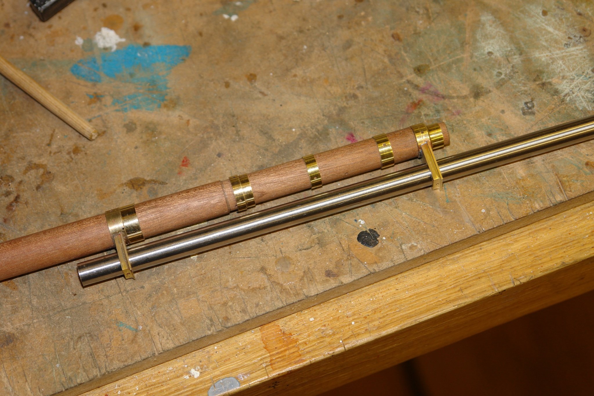
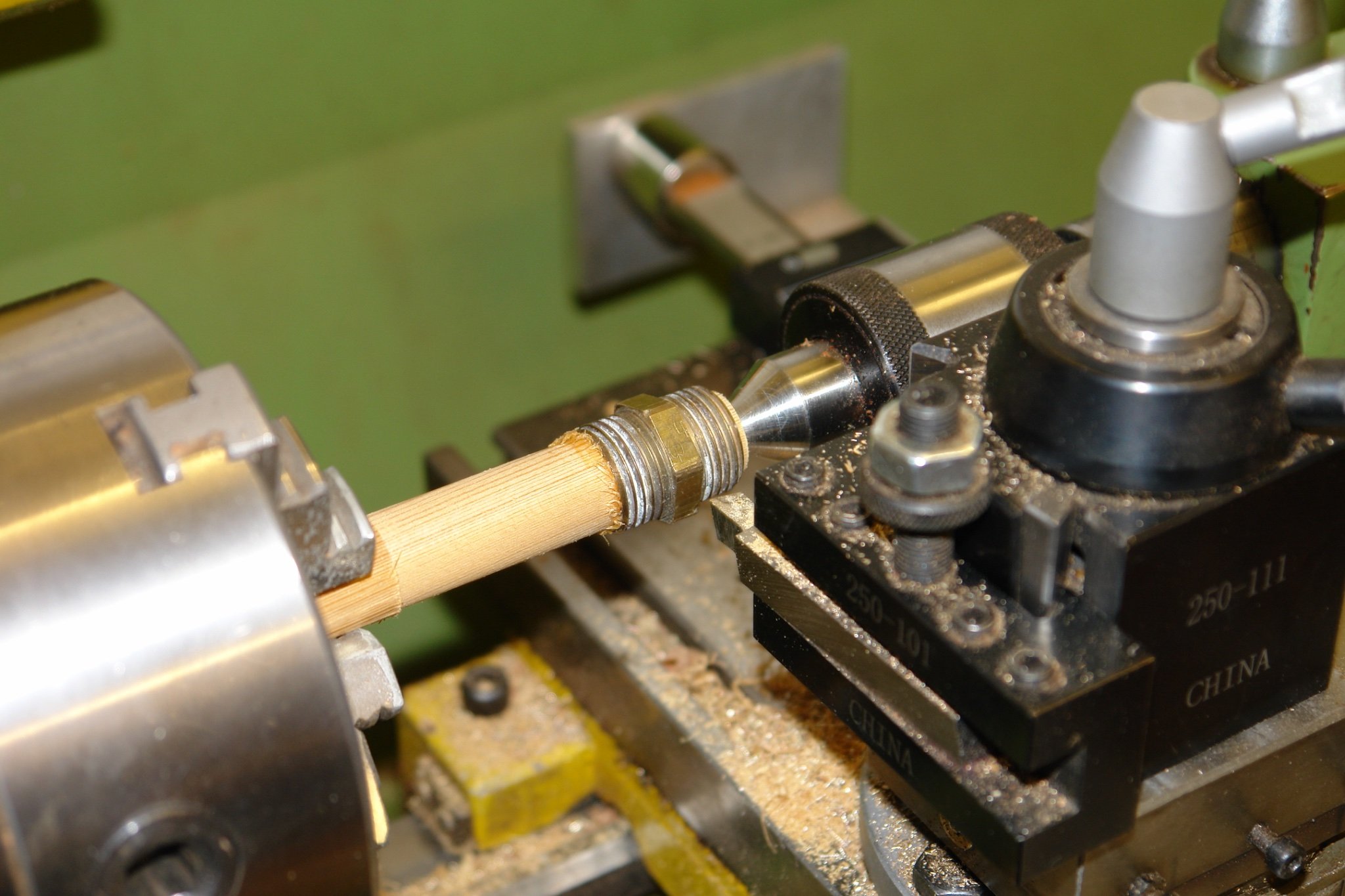
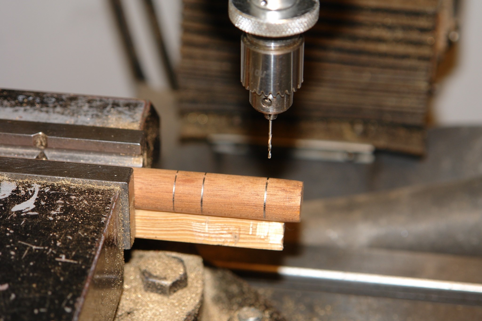
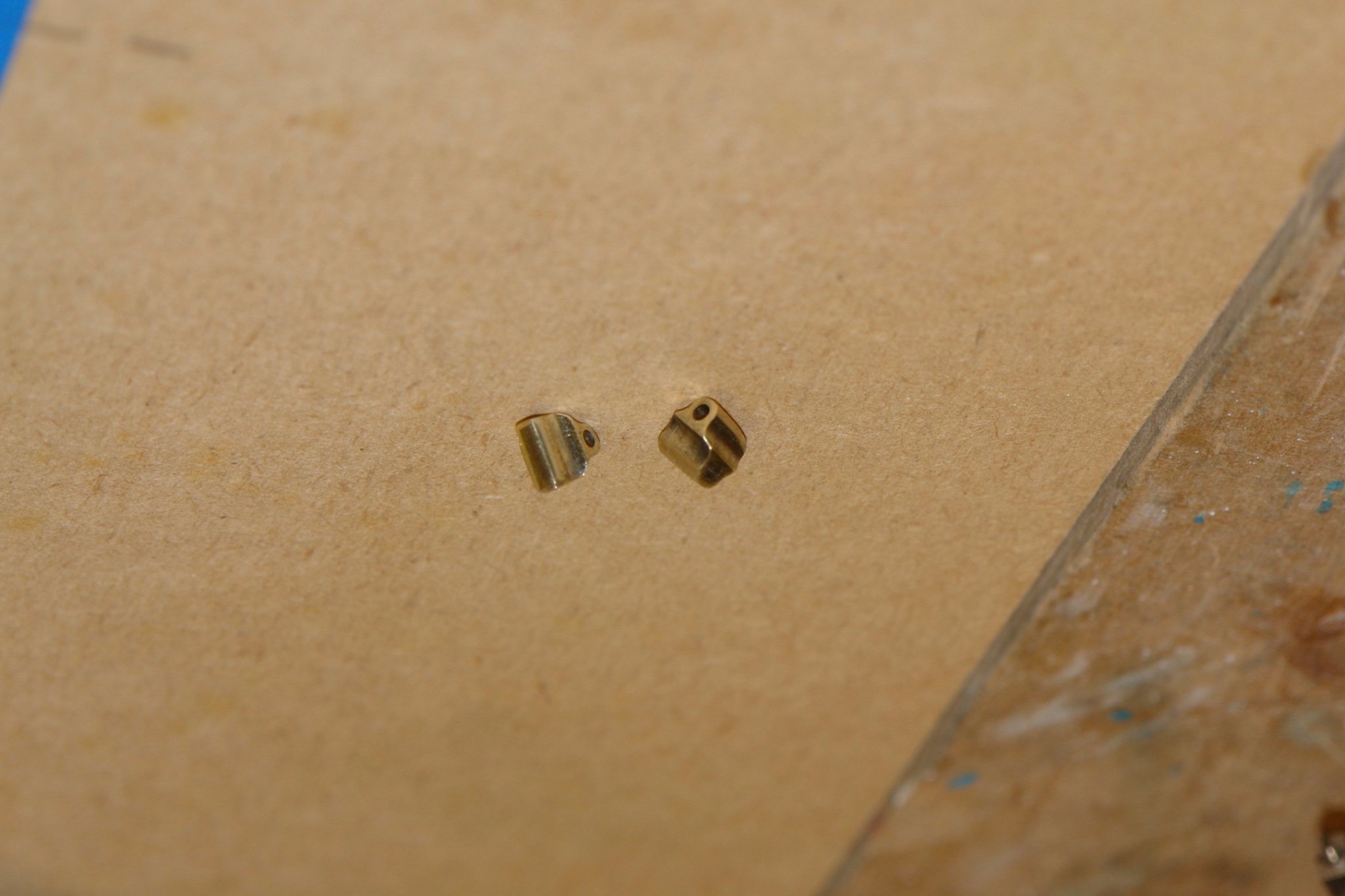
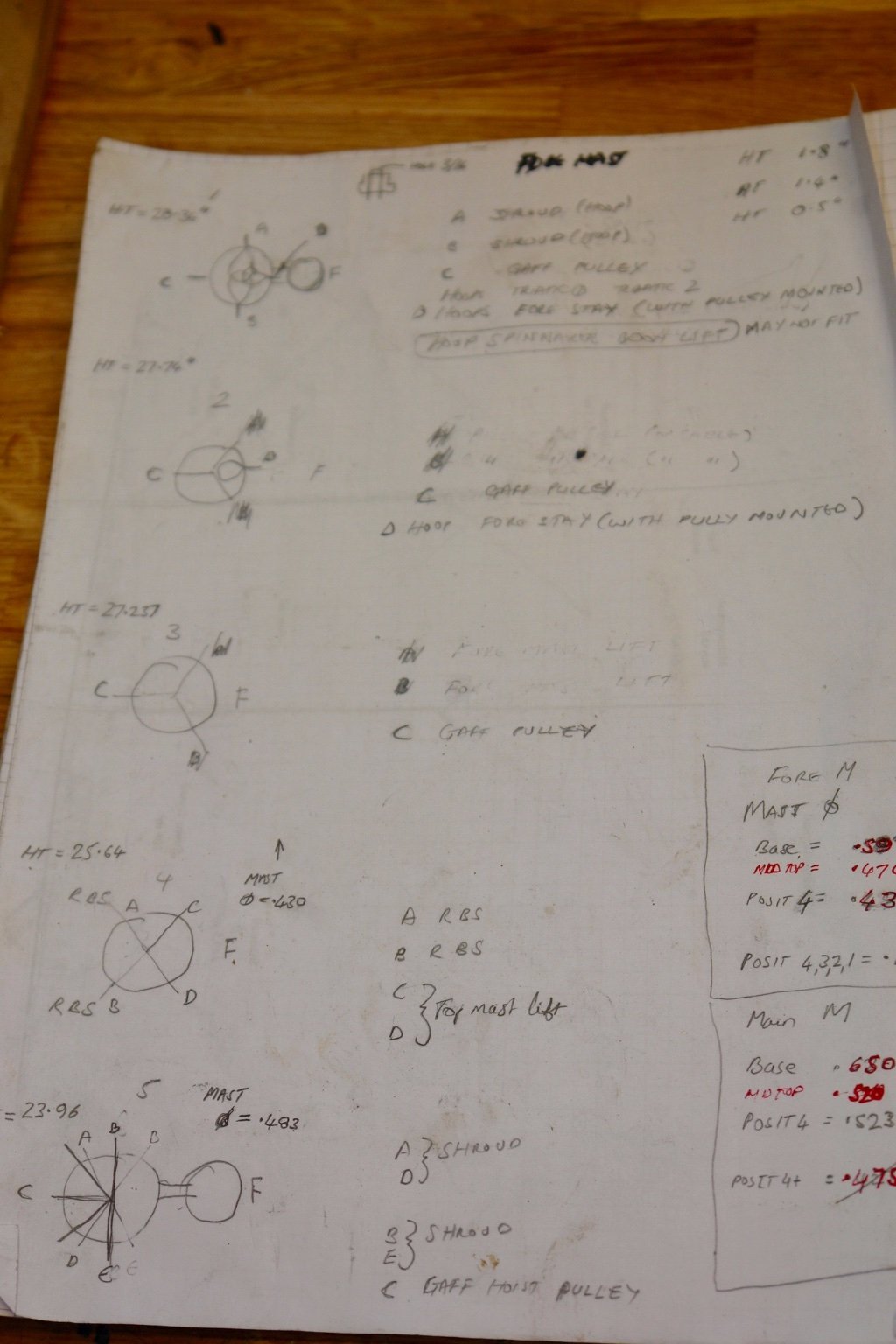
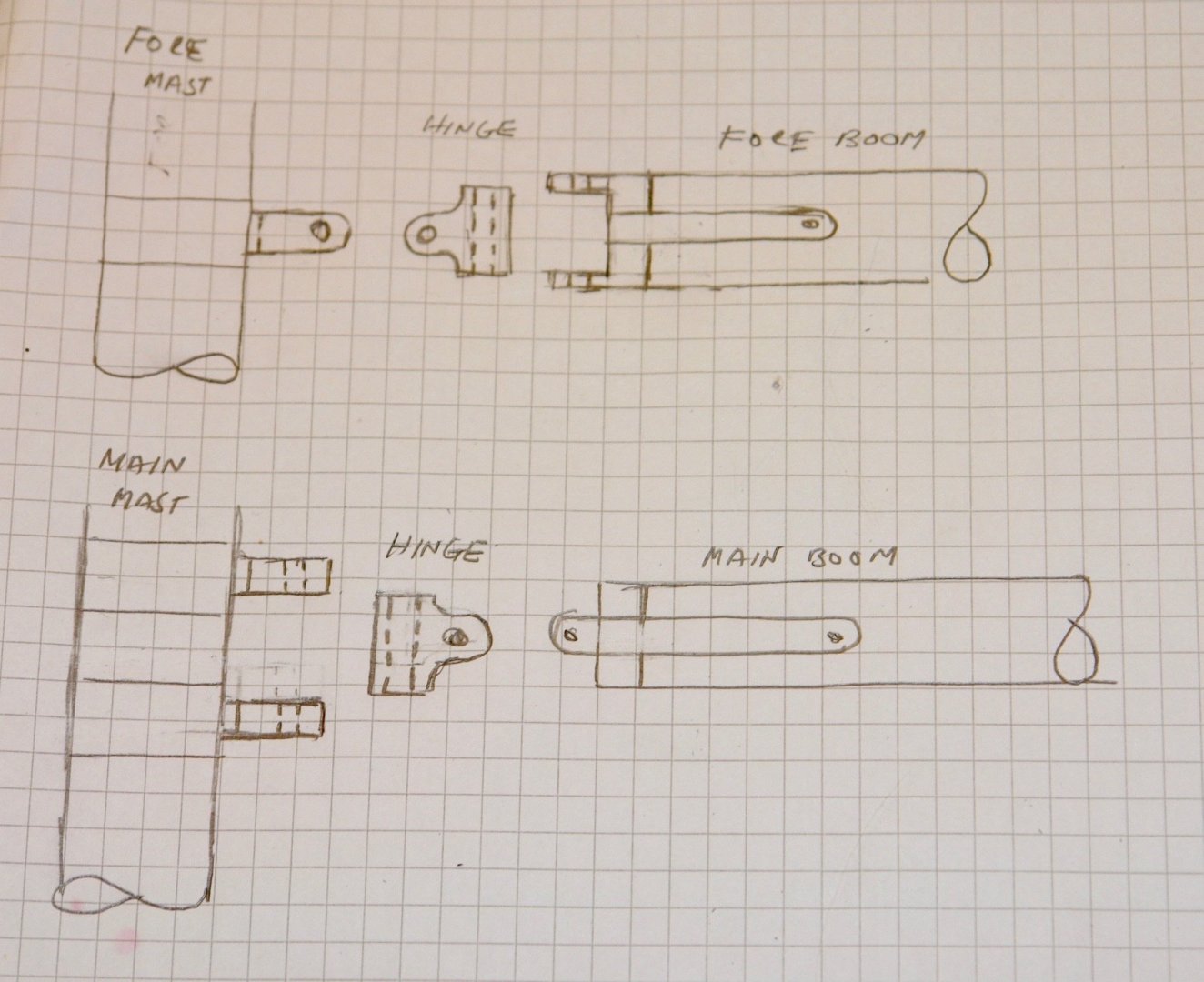
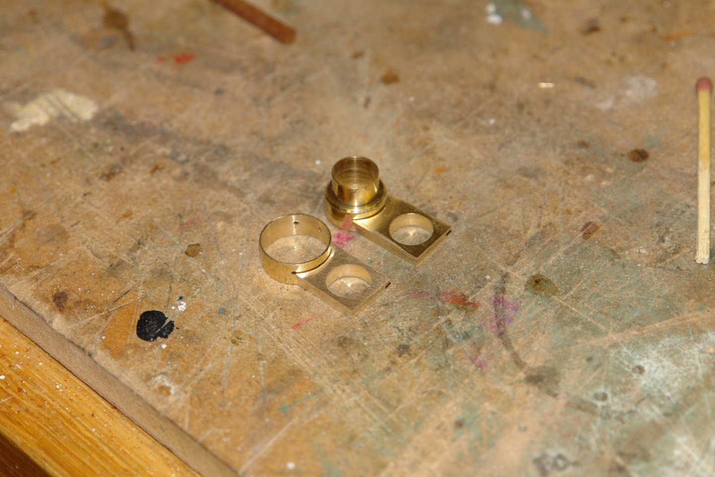
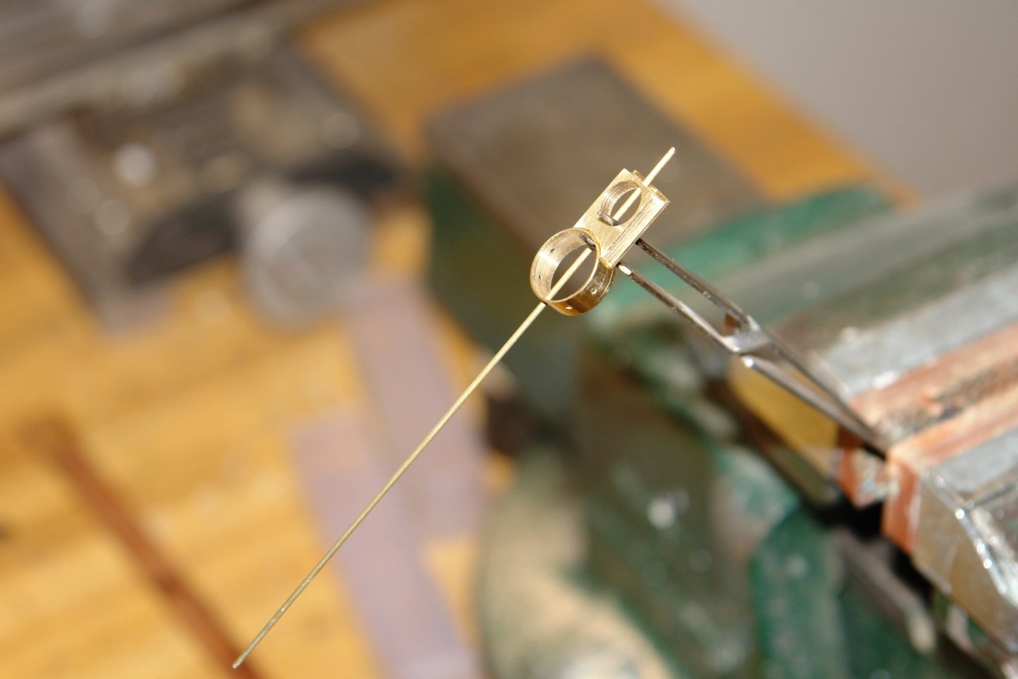
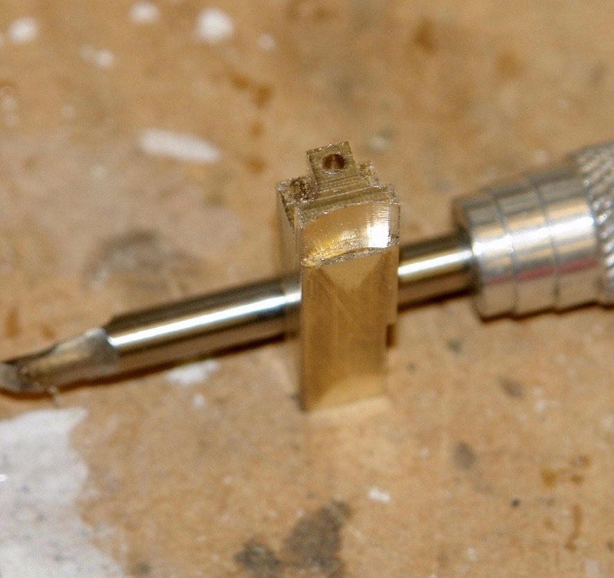
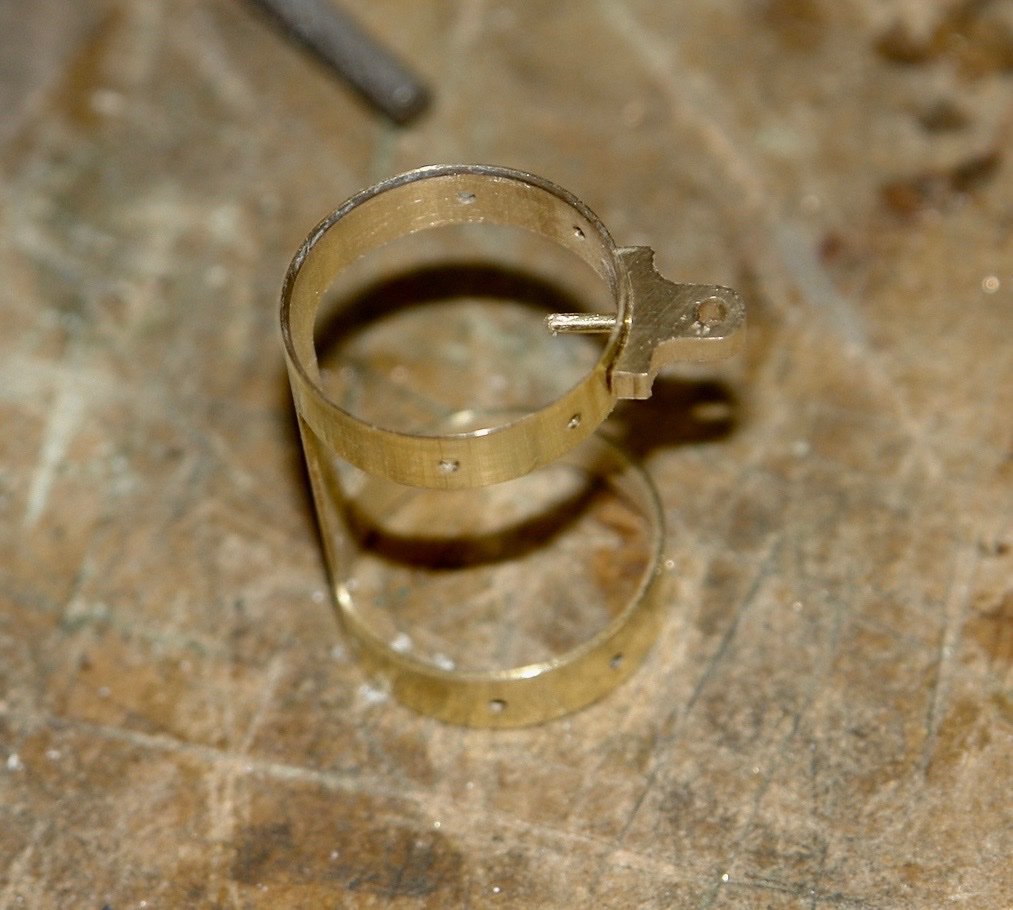
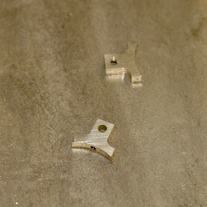
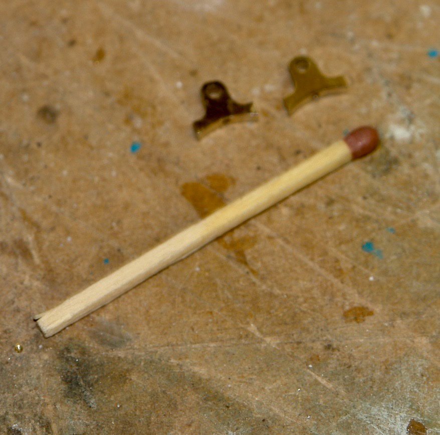
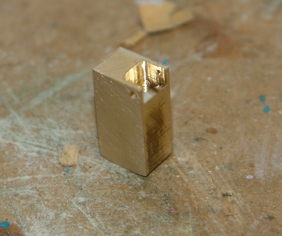
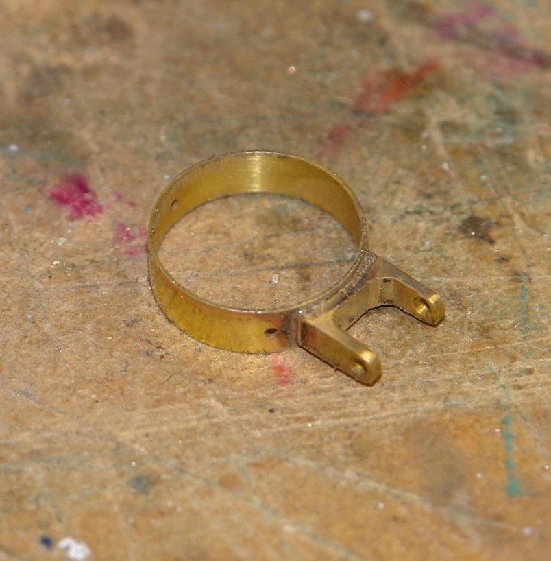
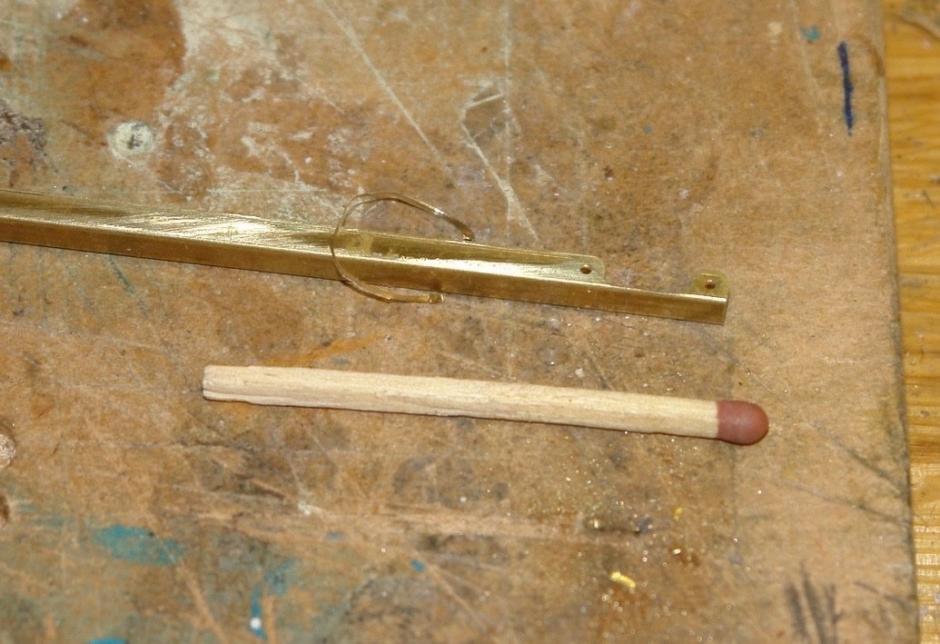
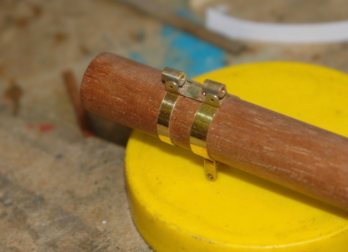
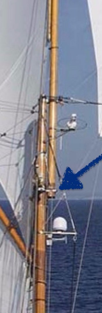
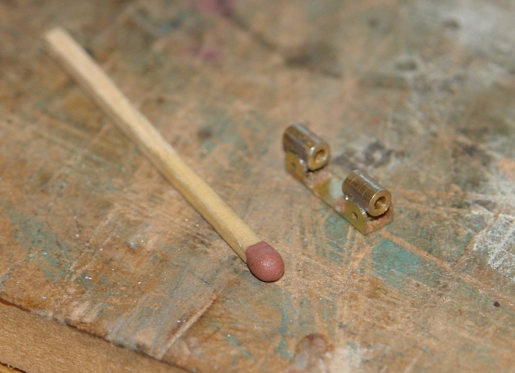
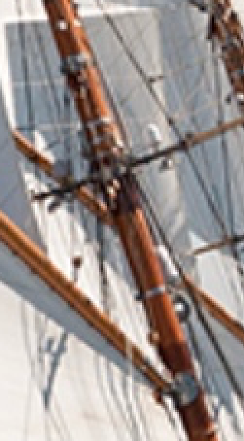
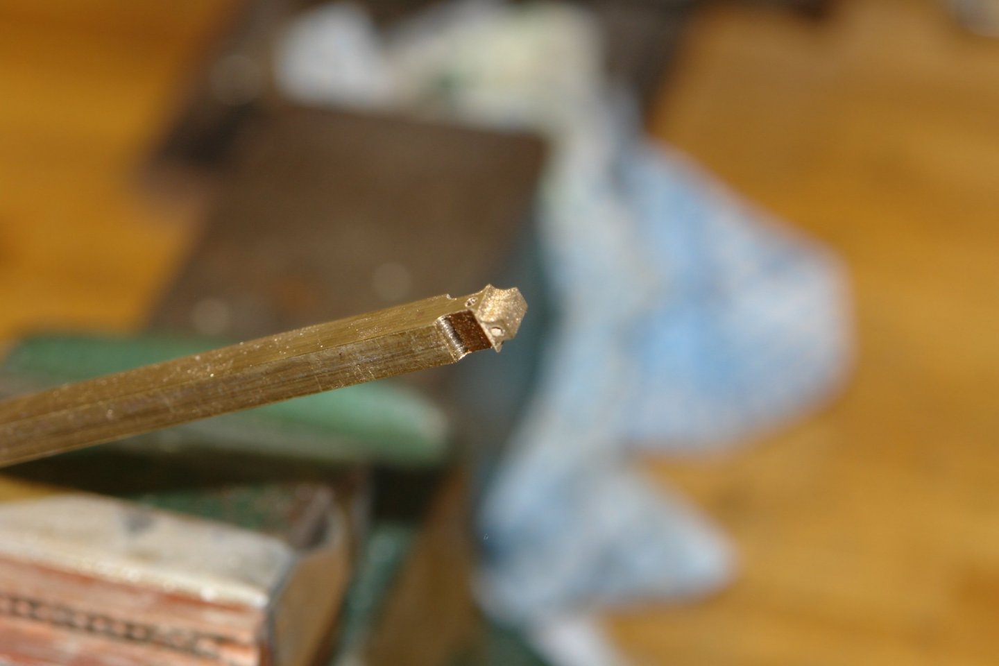
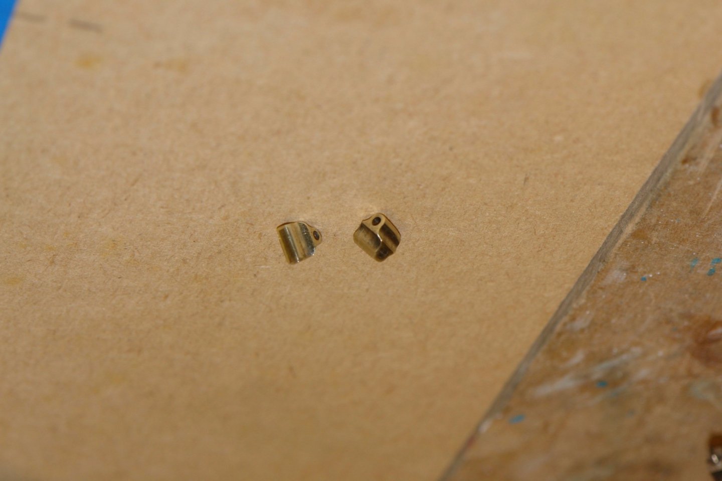
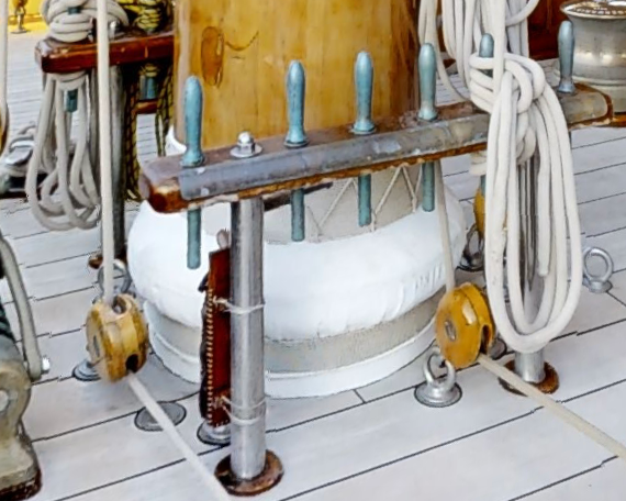
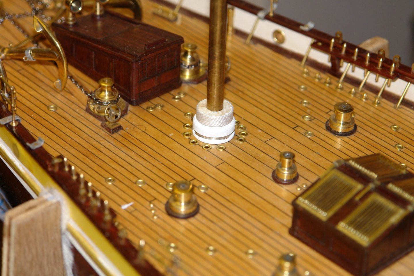
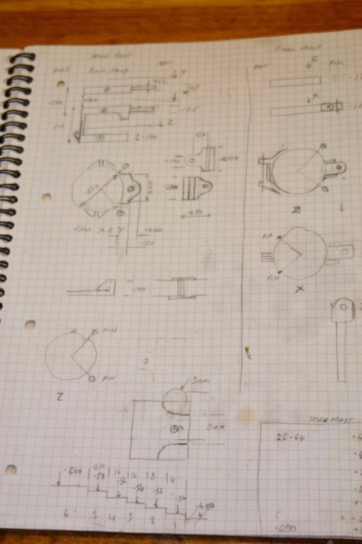
Thank You Druxey and Keith. At the risk of boring everyone I am proceeding with the mast fittings. Starting with the brackets for the main mast gooseneck. 2 brackets are mounted on separate bands to form the attachment points for the hinge. These were machined from .312" square section bar using end mills. The brackets were rounded using a file. The hole in the front edge takes a location spigot. They were then soldered in place. Small lugs were also attached to simulate the flanges on the band. The equivalent fitting on the fore mast has a horizontal axis for the hinge unlike the main mast which is vertical. It isn't obvious why the main and fore masts are different in this respect but interestingly the same discrepancy was also a feature of Altair. Does anyone know why this is so? Again the bracket was machined from .312" square bar using end mills and a bit of filing. I then went on to make and mount the mast bracket for the spinnaker boom. I then moved up to the brackets for attaching the top masts. These are quite indistinct on photographs but they seem to be square externally. See arrow. I made these from .5" x .125" brass rectangular section bar (more end milling). Because of the taper on the masts the hole to curved edge web distance has to be different thicknesses for the lower and upper brackets. This is necessary to make the axis of the top mast parallel with the axis of the lower mast. You can just about see the difference in the above photo. The two pairs are slightly different in size matching the difference in diameters of the main and fore masts. The next photo shows the brackets with their matching bands. Once again the parts have location spigots as seen in the next photo with the parts assembled ready for soldering. With the brackets soldered they were test fitted to the mast with a steel bar representing the upper mast. The workshop is starting to feel a bit colder - 10c (50f) today. I was feeling a bit cold after 4 hours. I may need to break out a second jumper.


-
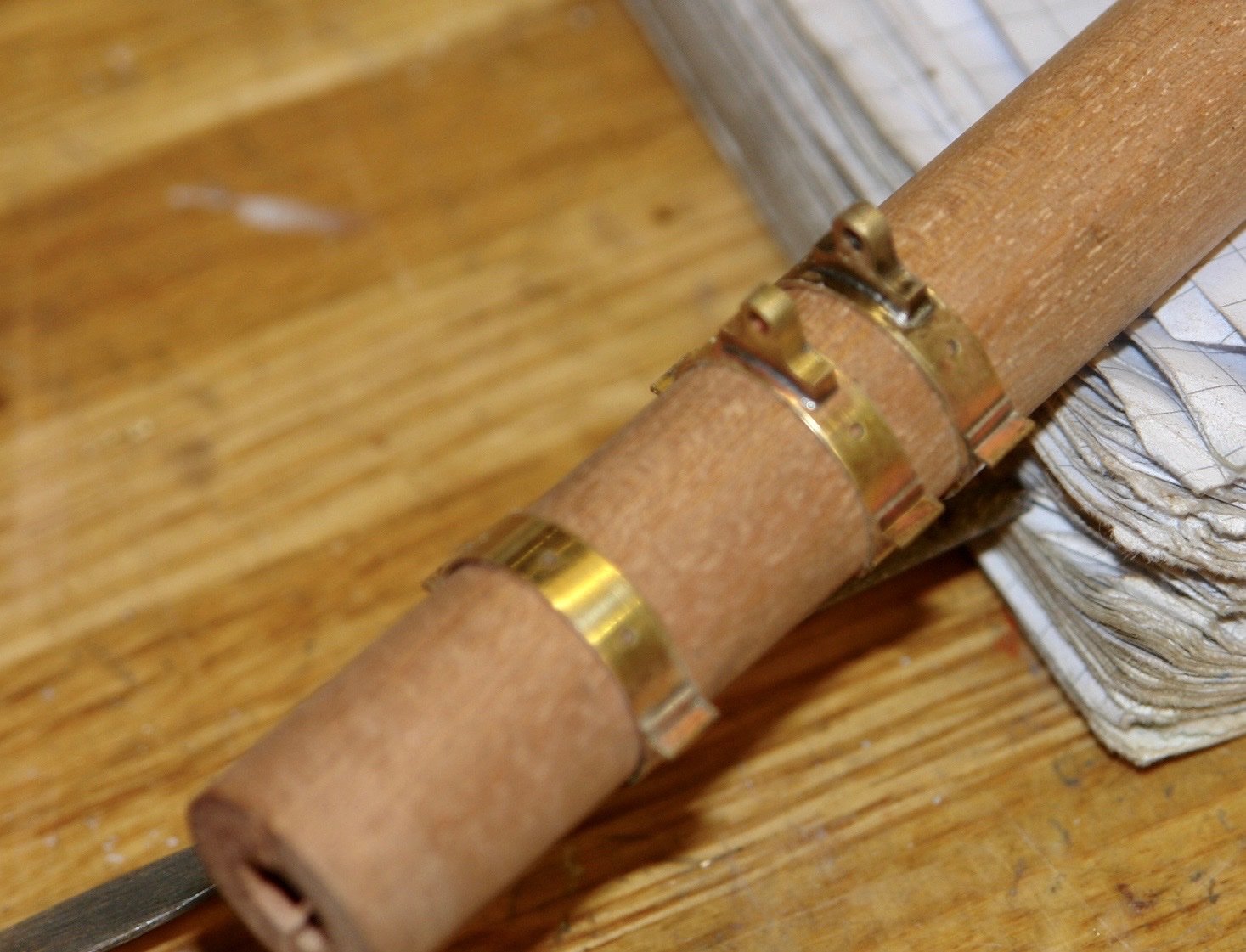
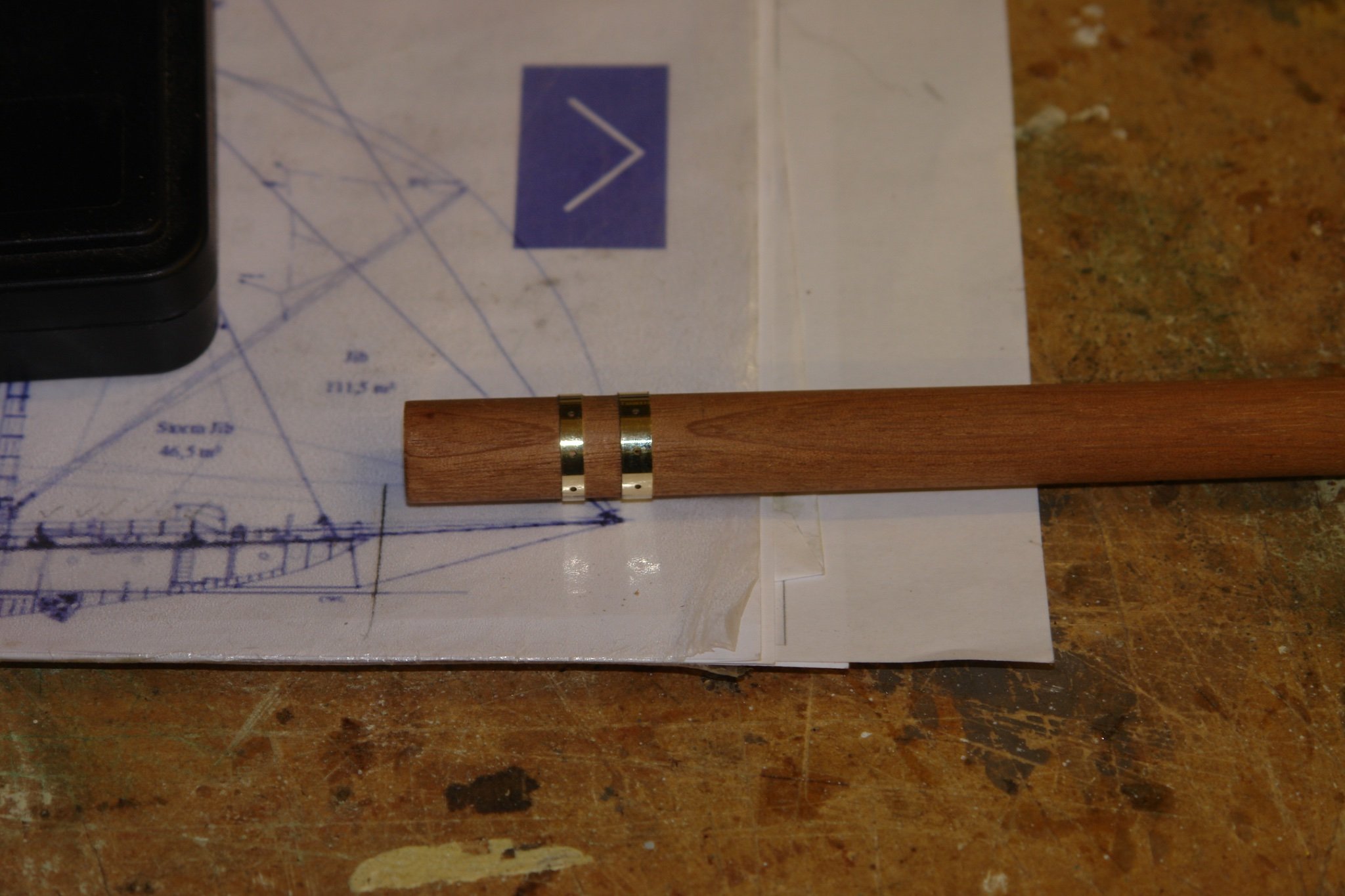
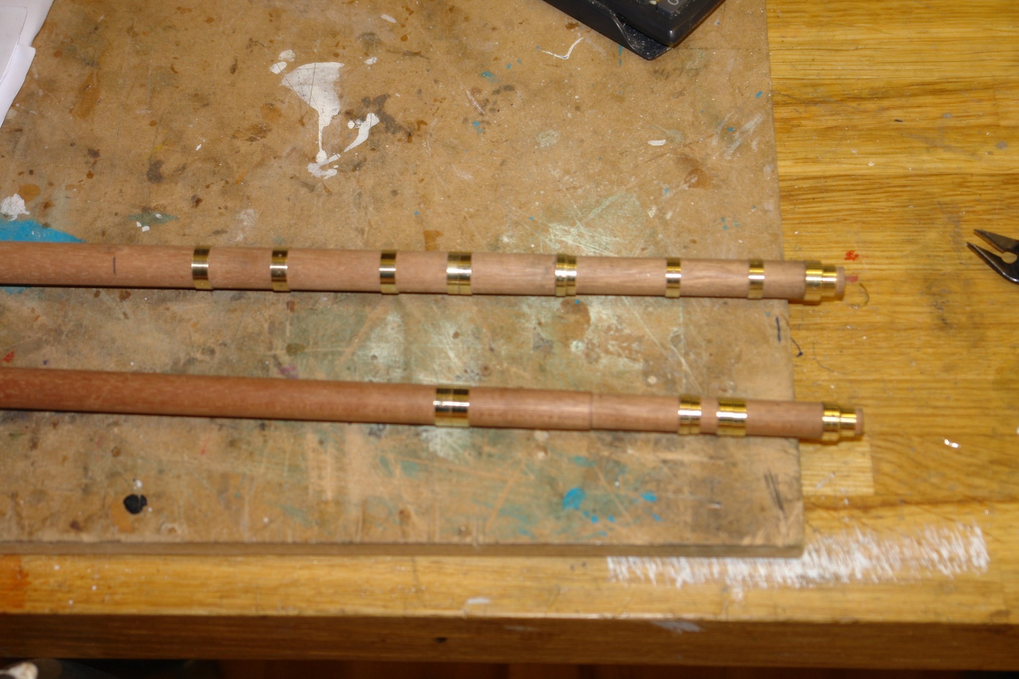
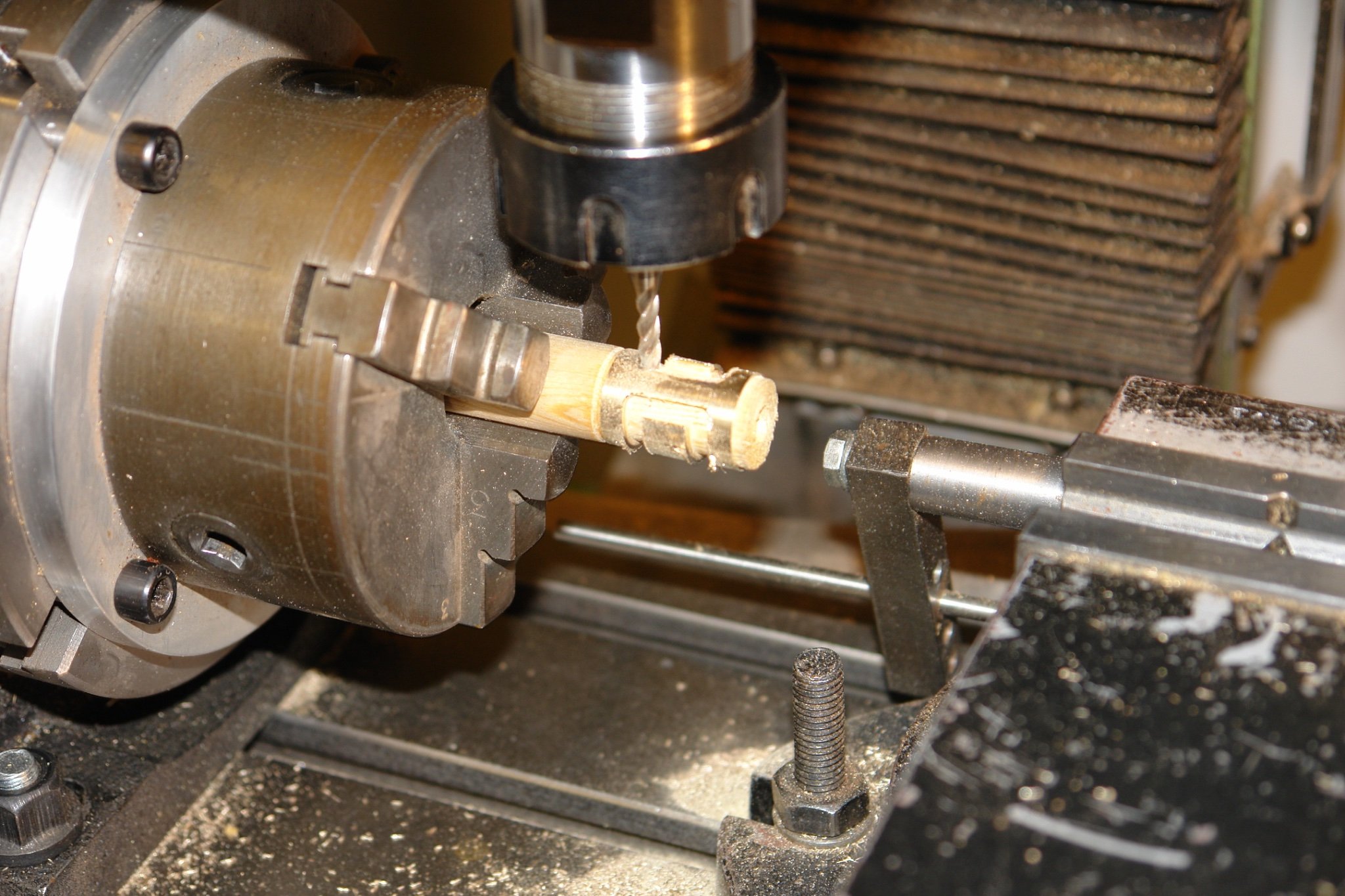
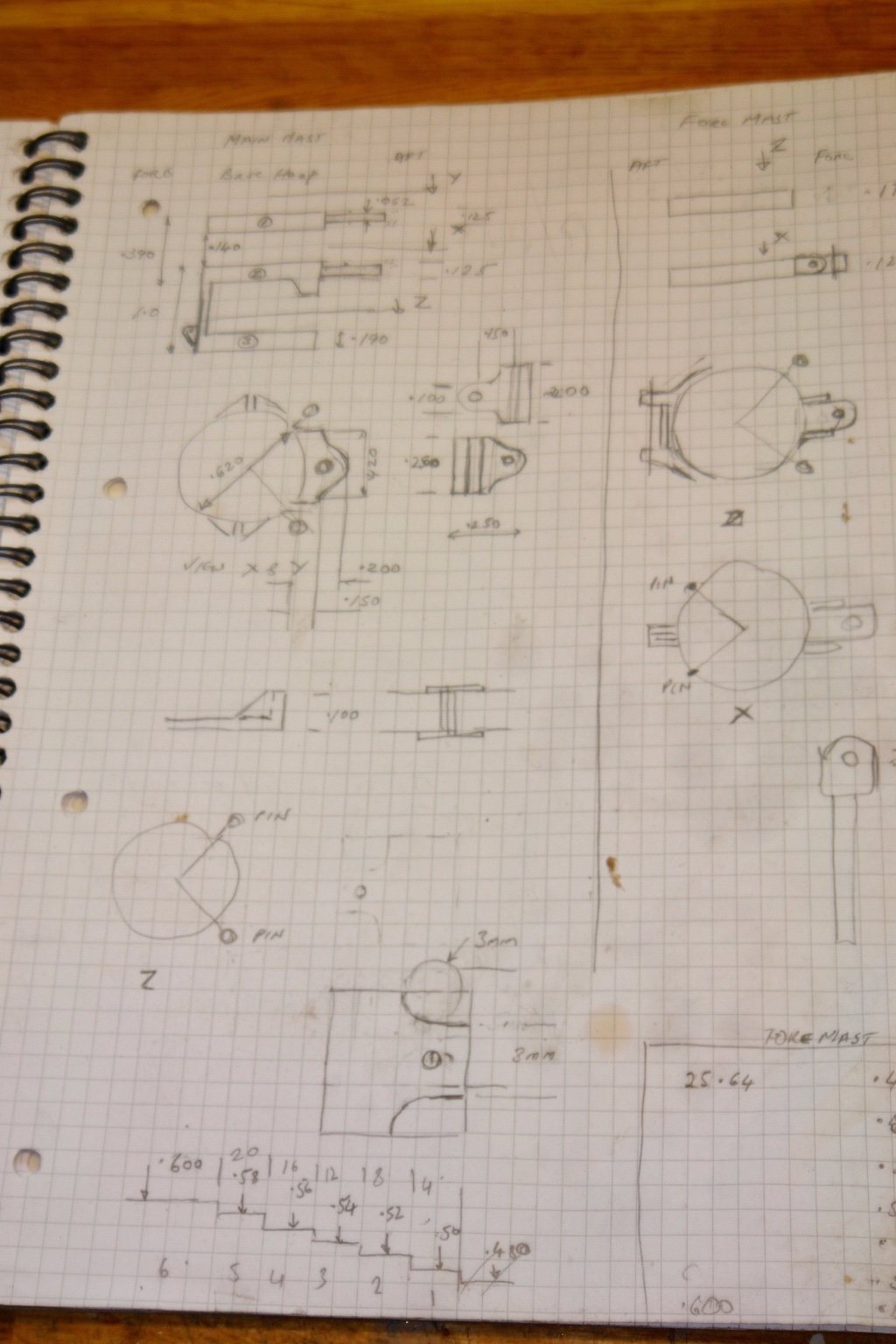
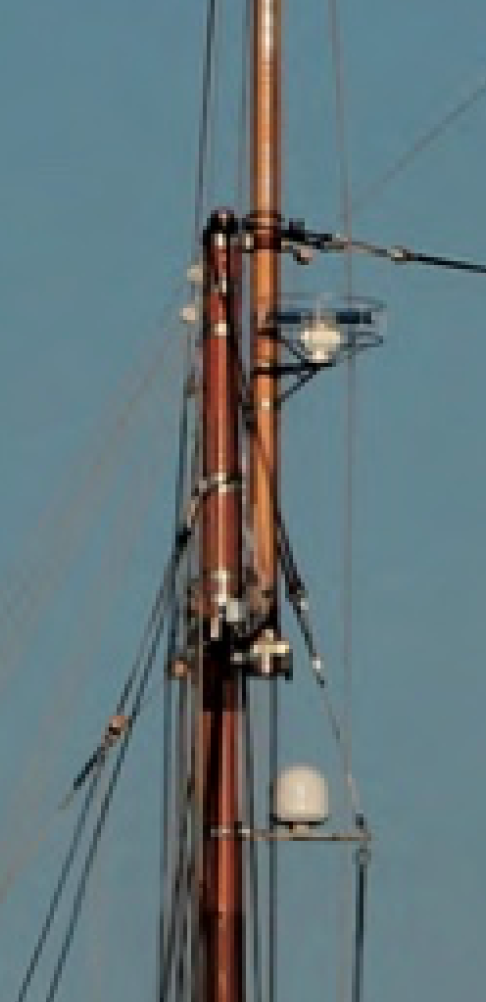
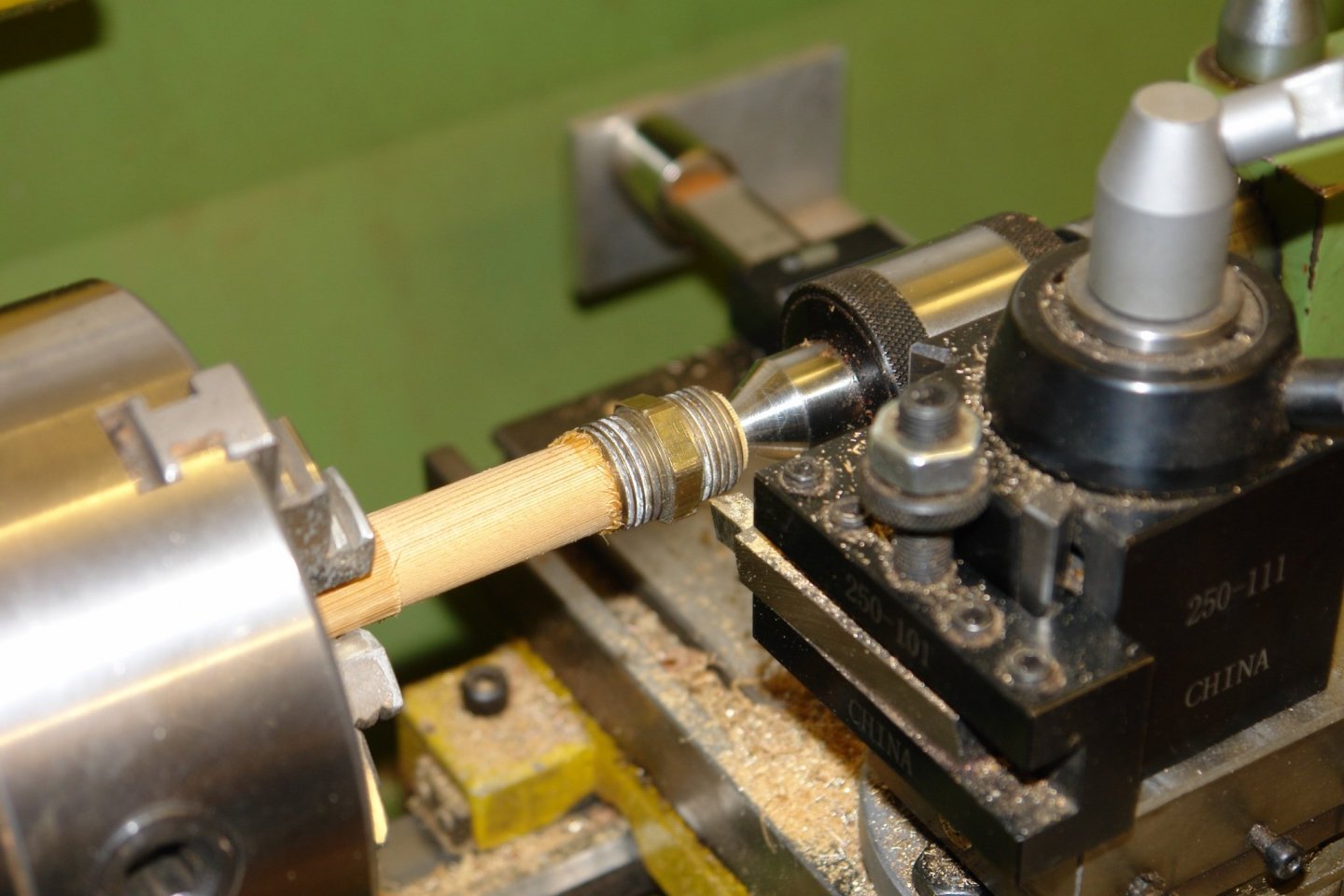
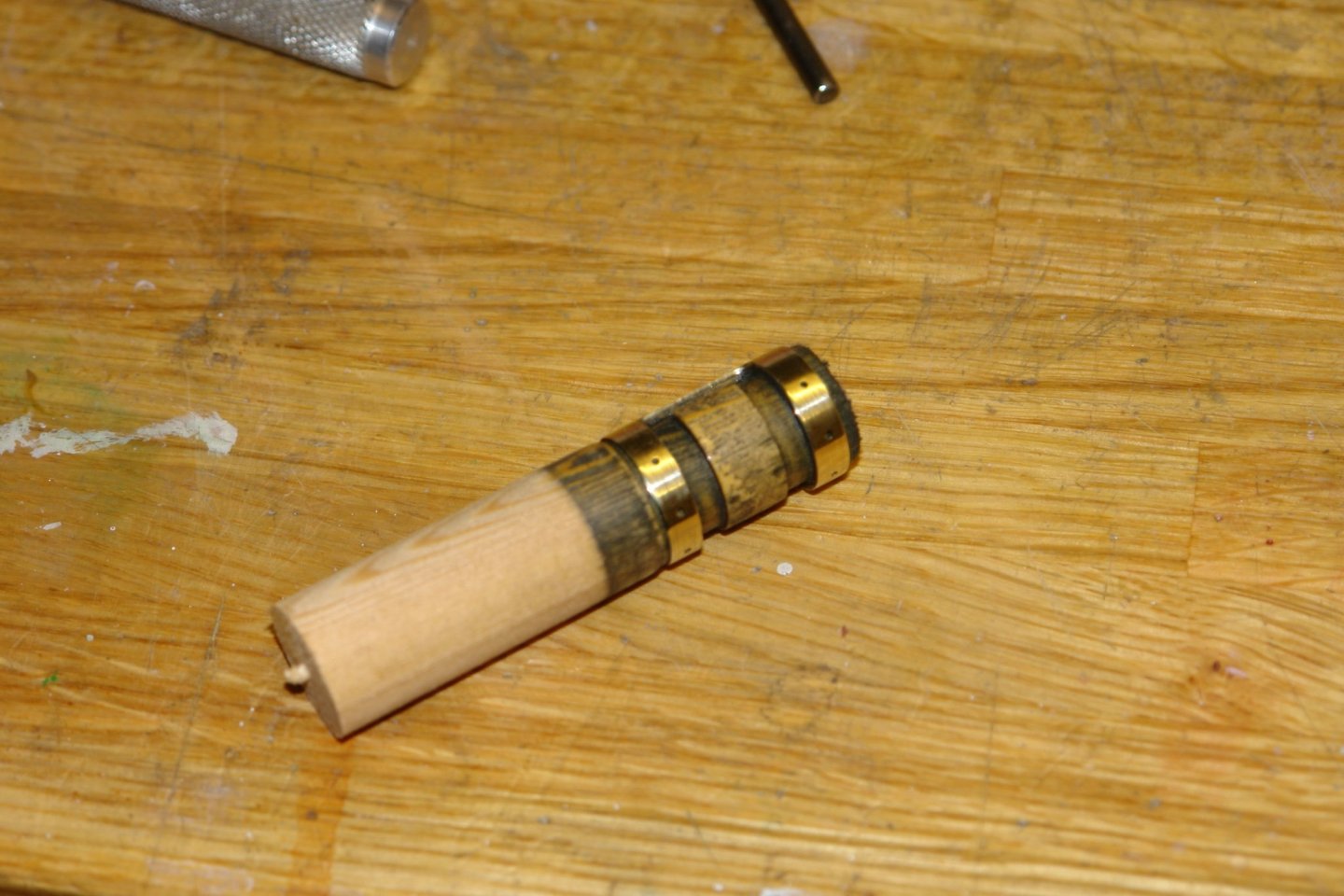
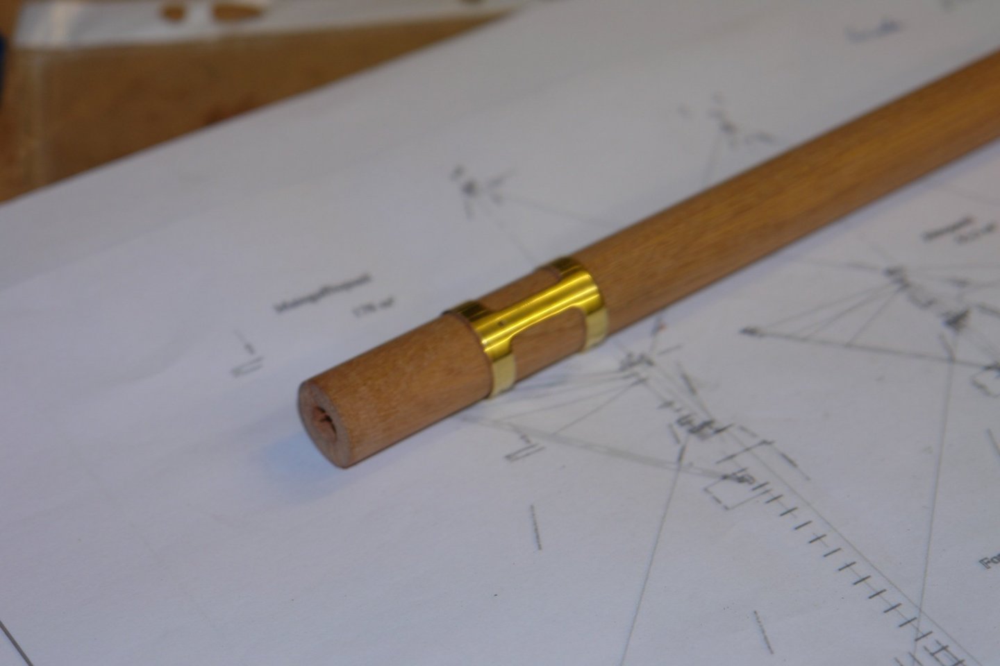
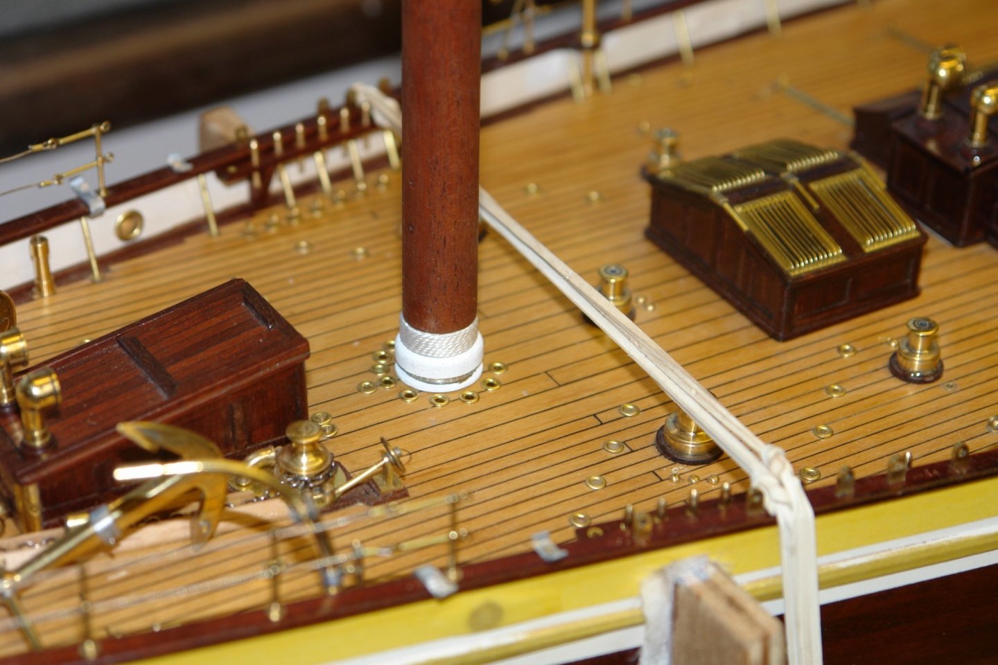
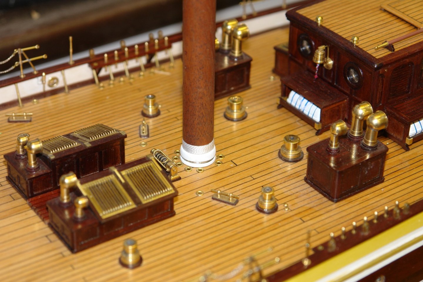
Hello Michael - yes and it was very quick to make. It saves a lot of time looking for the holders particularly if I keep them in the same order. I always find I have 2 holders less than I need, but when I but 2 I am still 2 short. Thank you for the comments. John / Eberhard thank you and thanks to everyone for for all the likes. And so to the mast bands. At deck level I have fairly good images of the various mast fittings, but as I raise my eyes to the heavens everything becomes a little vague. The following series of shots gives a feel of what I am dealing with. The images gave plenty of scope for interpretation - which I don't really like. However I pressed on regardless. I can't make the manufacture of bands very interesting - mostly it is matter of turning internal and external diameters with small radial holes (for eyebolts) being machined on the mill. The most interesting part was sorting out tube stock, near enough in size to minimise waste. Where I didn't have appropriately sized tube my box of redundant brass plumbing fittings came in handy, It wasn't an inspiring task so when a slightly more complex band presented itself it was a bit of a relief. `Such was the case with the dual band at the bottom of the main mast. Here two bands are connected by a vertical strip. I started with a 1/2 inch plumbing connector which I bored out to the desired internal diameter and then glued to a wooden spigot. The outside diameter was then turned before moving to the mill with a vertically mounted rotary table. Using an end mill I cut away the unwanted walls. The various radial holes were then drilled. The application of a little heat broke the superglue bond and allowed the part to be removed and checked on the mast. That is it but for now but I do have all the bands for the main and fore masts so the next post may be a little more interesting.


-
I do admire your commitment to detail, A beautiful little ship.
-
Keith - Maybe you can emulate the "Scarecrow" and get a diploma in rigging, then you can be really smart.
-
Hakan, Sailing is much better excuse for lack of progress than my excuse of household maintenance. She is a cute little tub and so nicely made. Good luck with the treatment and get well soon.
-
lovely paint job Eberhard. You seem to have made rapid progress of late, is it the sprint to the finish?
-
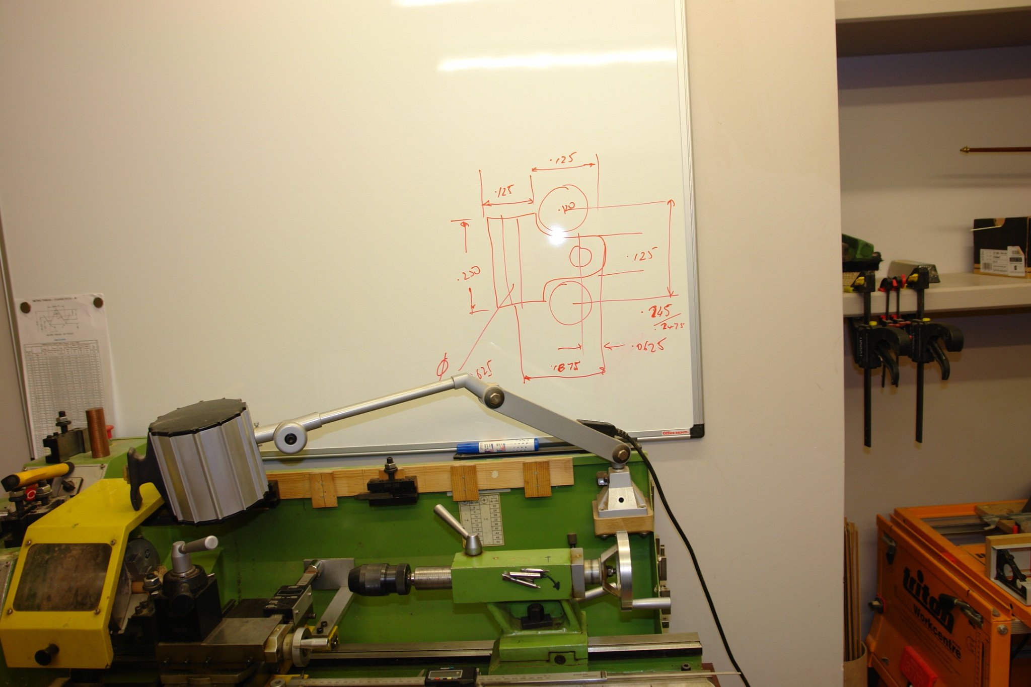
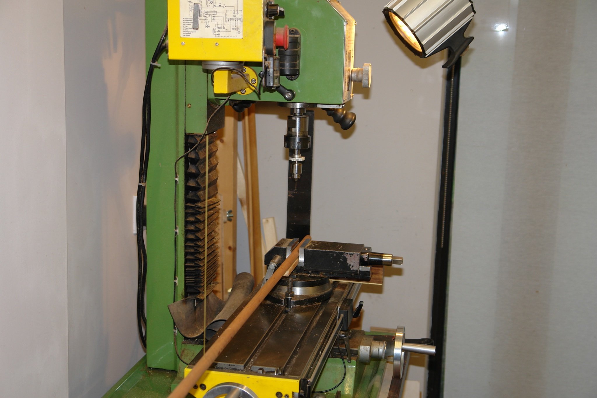
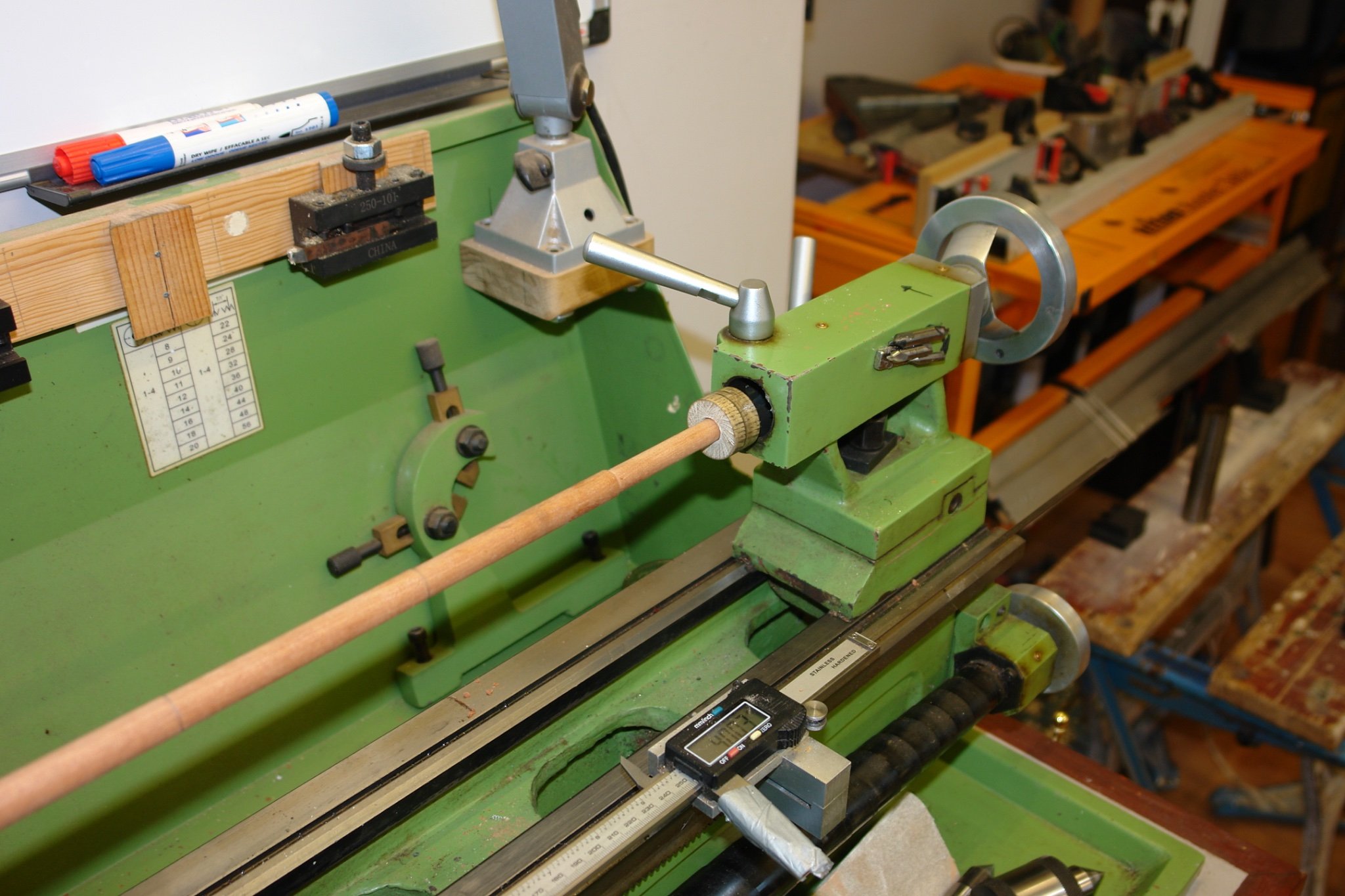
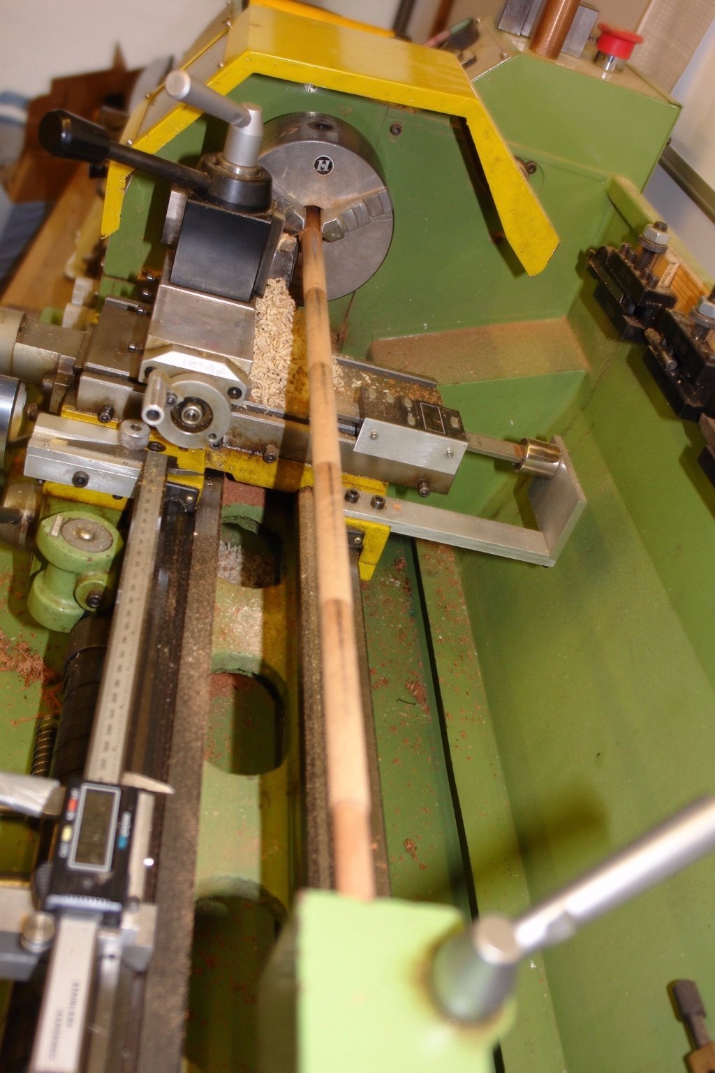
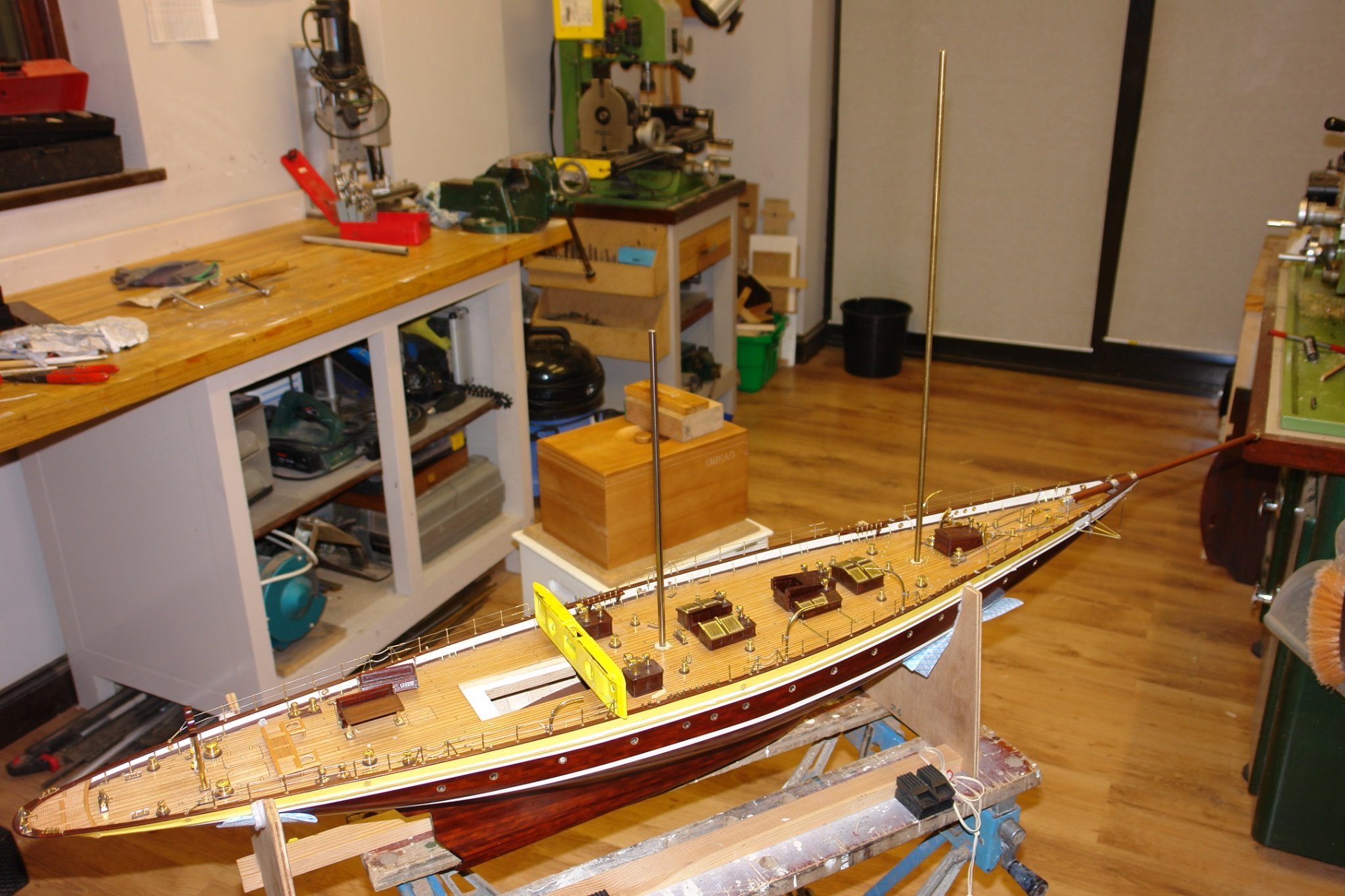
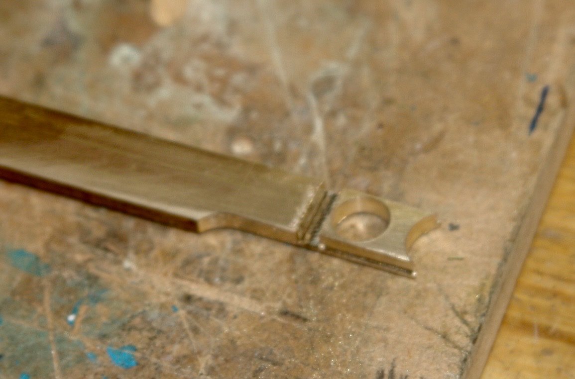
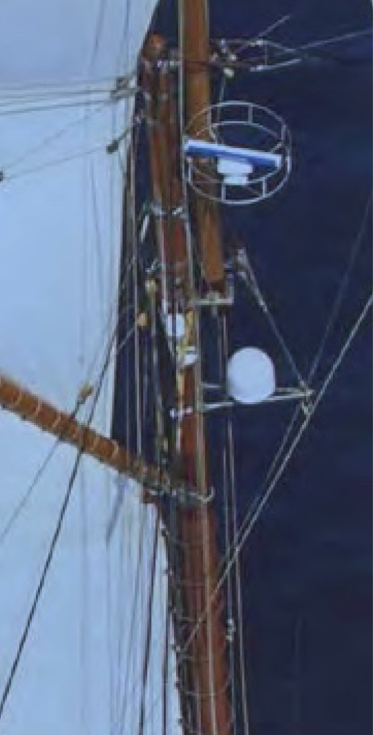
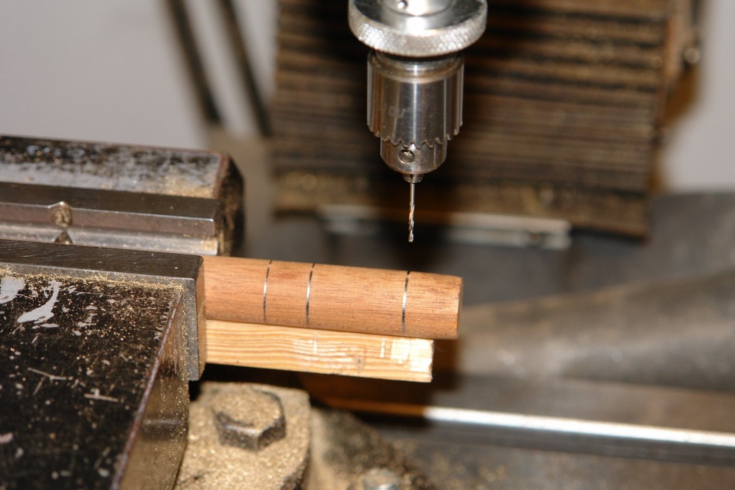
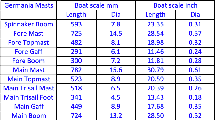
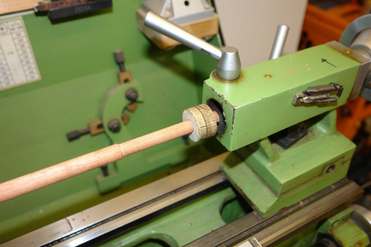
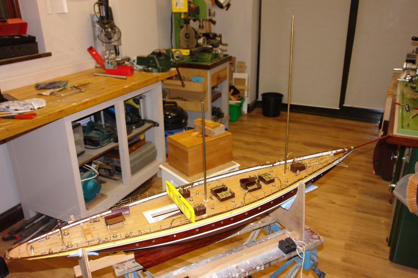
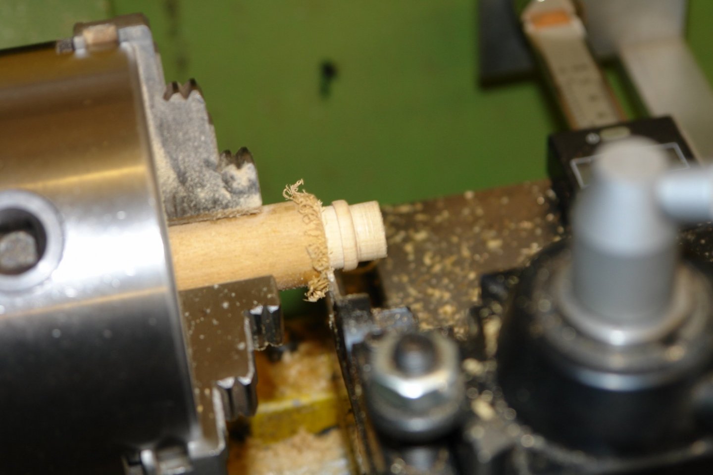
Druxey, Pat, Gary - thank you all for your comments. Last week I made the hinges for the goosenecks. I did the sketch on the whiteboard (a handy addition to the workshop). . Complicated little pieces to make, they were milled from .250" square brass bar using the sides and face of a .125 diameter end mill. The through holes are .062" diameter. The outside curves were filed using filing buttons. I then moved on to making a start on the masts. I have sized all the masts and spars, 11 in all excluding the bowsprit which is already made and fitted. The fore and main mast were made from mahogany dowel. Having cut 2 lengths for the main and fore masts i marked the positions for all the mast hoops. I then drilled each position with a through hole of .040"diameter so that the position wasn't lost during further machining operations. I calculated a series of cylinders to give me the correct taper and then machined the cylinders on to the mahogany dowel, The mast lengths are longer than I can cope with on my lathe so I took the tailstock apart and used an oak bush in the bore as a steady. With this set up I machined the cylinders. Once done the steps were removed by sanding to produce a smooth taper. The 2 masts were drilled axially to fit over the steel bars previously installed in the deck. Once stained and finished the masts were positioned on the steel bars to see what the looked like.


-
You sanded your wife!!!!! Brave man.
-
Nice work Roger, and i really liked the workbench paint scheme.
-
Very impressive Richard. Planning looks impeccable.
- 454 replies
-
- 2
-
-
- Union Steamship Company
- Stepcraft 840
- (and 3 more)
-
Starting to look very smart Jon. She was quite a substantial vessel wasn't she.
-
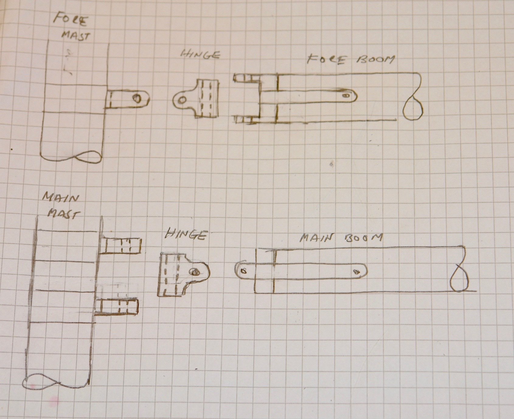
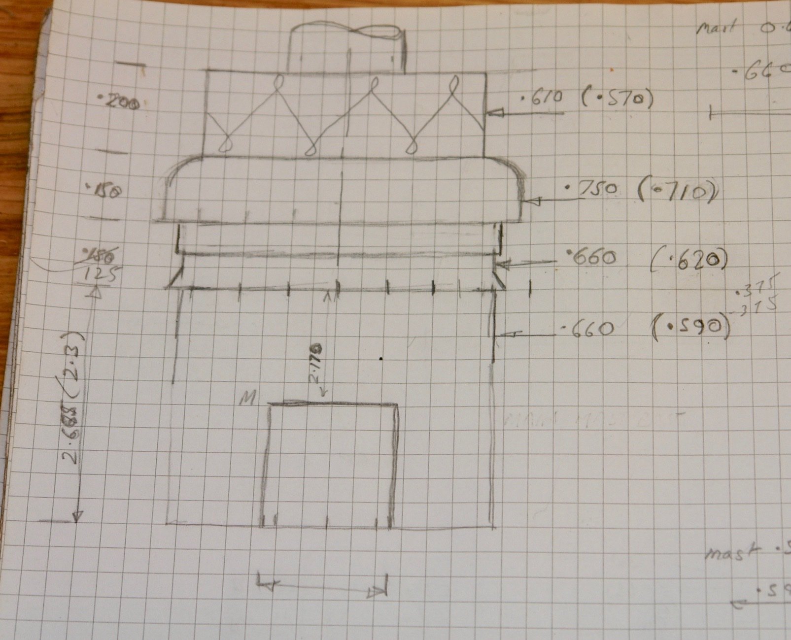
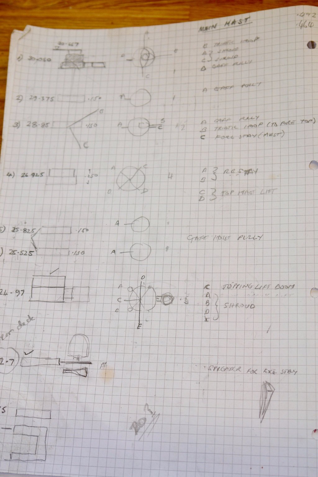
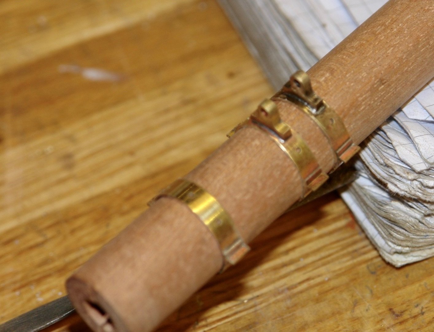
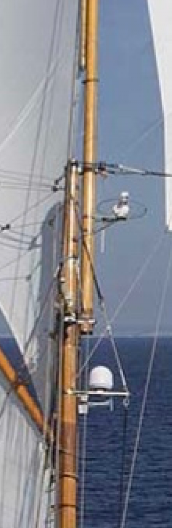
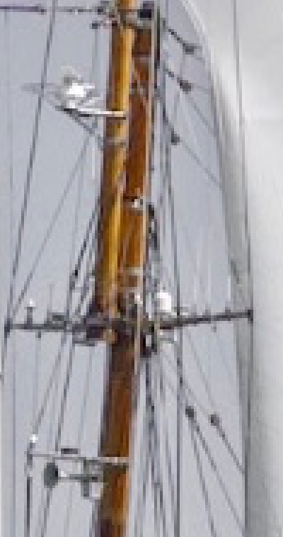
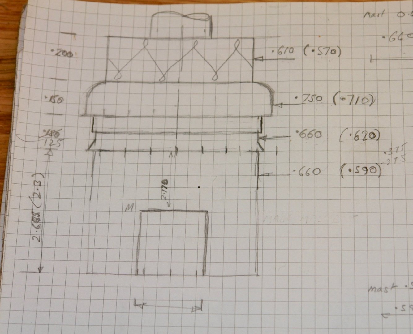
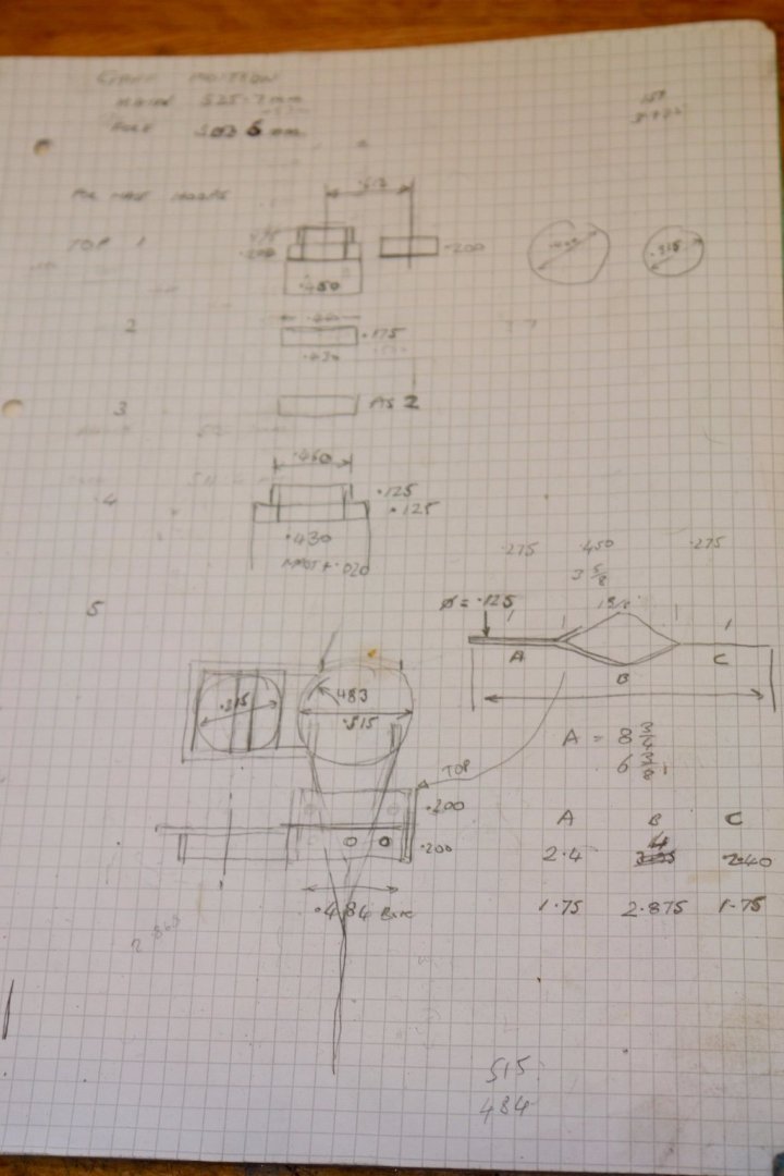
Agreed Mark! A minor manufacturing jobs done this week together with one complicated and frustrating task. Starting with the job. With the temporary metal masts in place the next job was to make the boots. I had decent photographs from which to produce the drawings. The only difference between the two boots was the difference in the mast diameter. The boots are canvas but at model scale material does not work well so they were made from painted wood. They were made in 3 parts with an intermediate aluminium disc to simulate the clamping band. Then came the frustrating task of sorting out the locations and designs of the various mast bands for both masts. Unfortunately when it comes to masts photographers don't seem to find them very interesting. The photographs I have are therefore indistinct and confusing. The plans don't really help with anything other than the locations of the intersections of the rigging lines. Trying to interpret the photos did my head in but in the end I think I got it about right. I now have loads of sketches which I hope I can understand when I come to use them. I have included a selection below/


-
Lovely start on the planking JD. I am always impressed with how dedicated some of you are with planning and executing the planking. My planking plans never survive 1st contact with the frames. Winging it is my default plan.