KeithAug
-
Posts
3,986 -
Joined
-
Last visited
Content Type
Profiles
Forums
Gallery
Events
Everything posted by KeithAug
-
 Remarkably crisp lines on the edge of the hand painted deck Eberhard. Not sure how you achieved that?
 -
Thank you Druxey, Pat and John. Thank you for your comments Allan. I'm not entirely sure. I sort of think it should go to my granddaughter when she grows up as it includes some of her baby photos. However my daughter has eyes on it for her new house. I think it will sit on a lounge table for a while (maybe years) waiting for a decision on its final resting place.
-
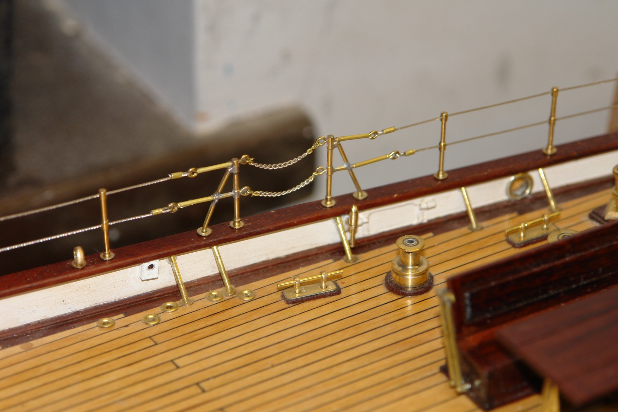
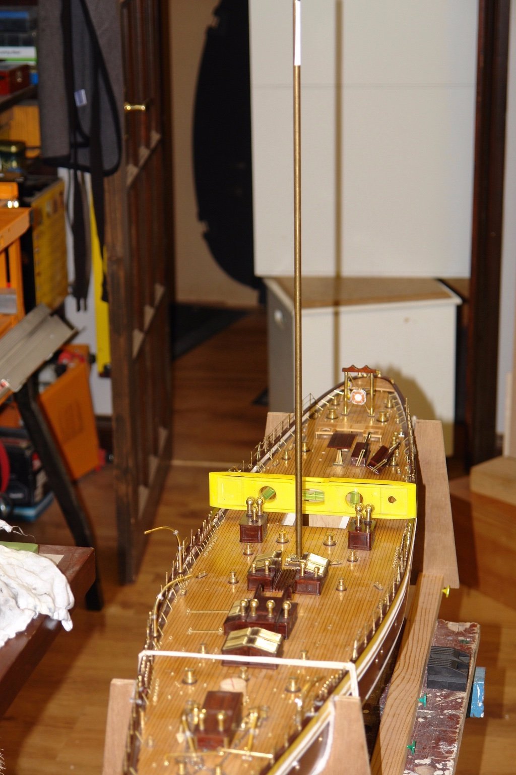
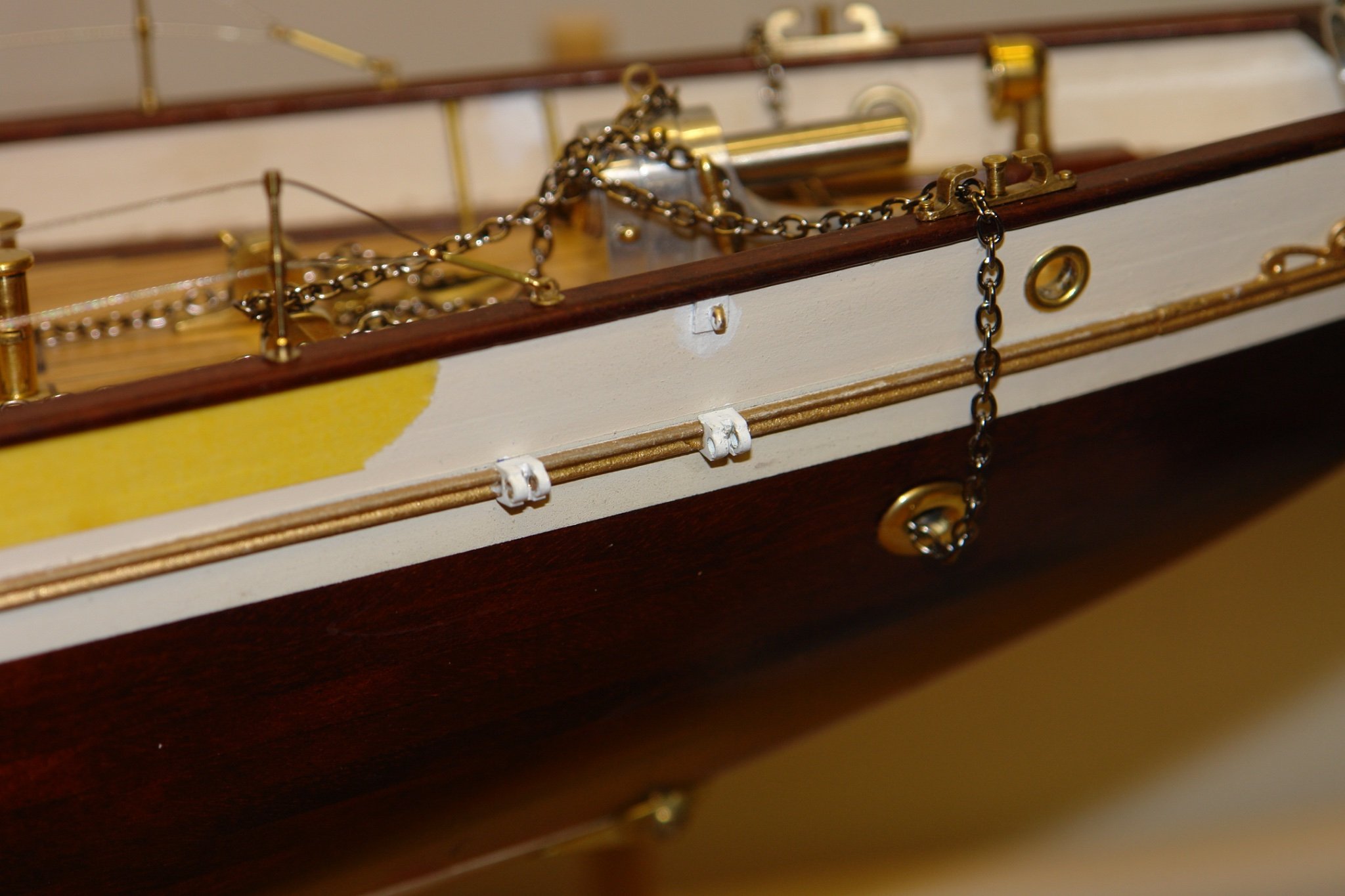
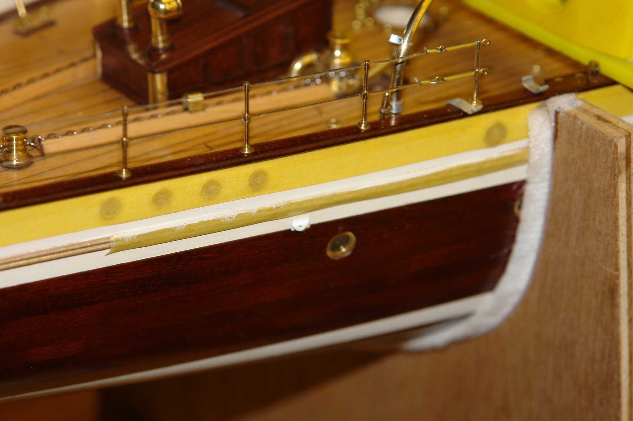
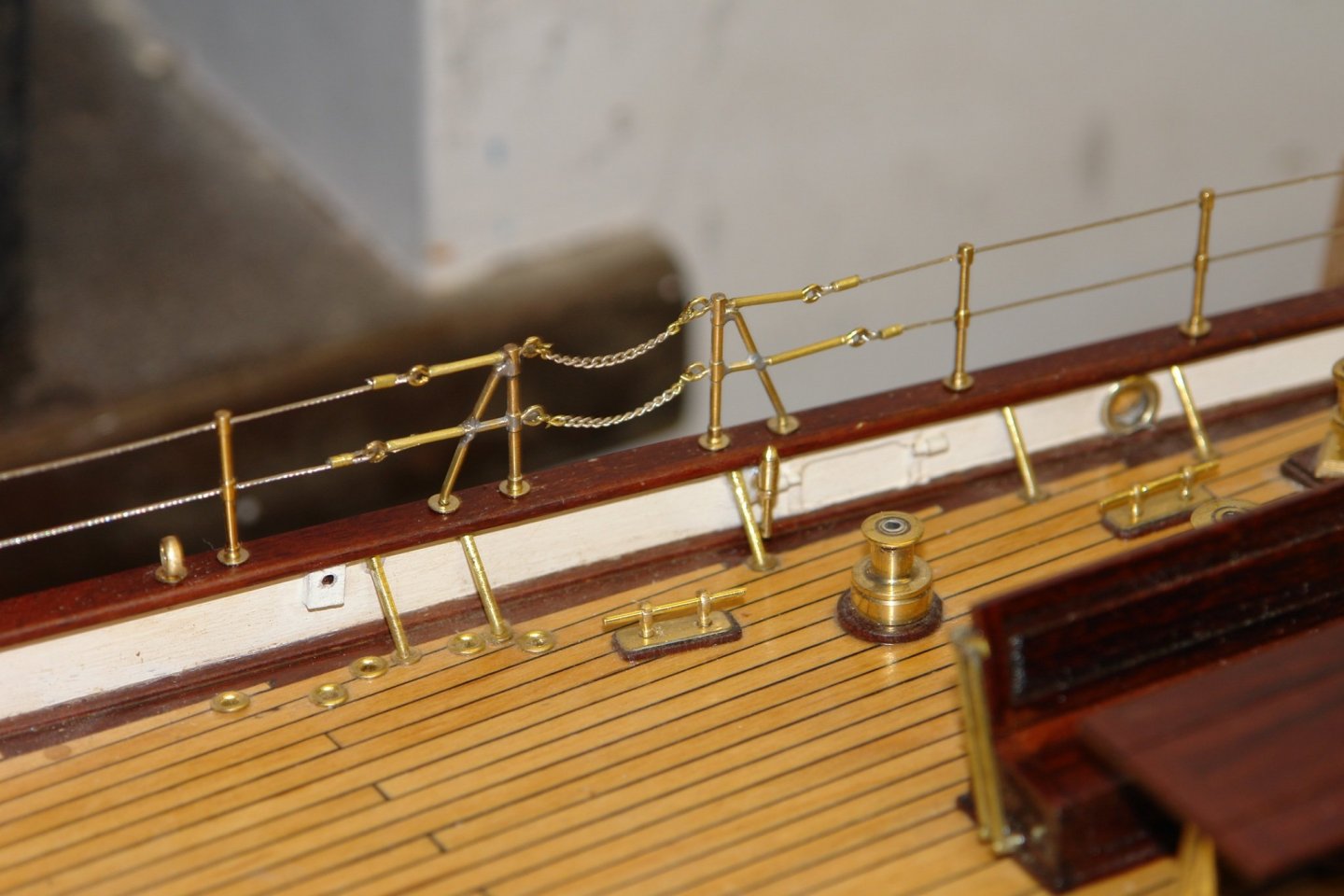
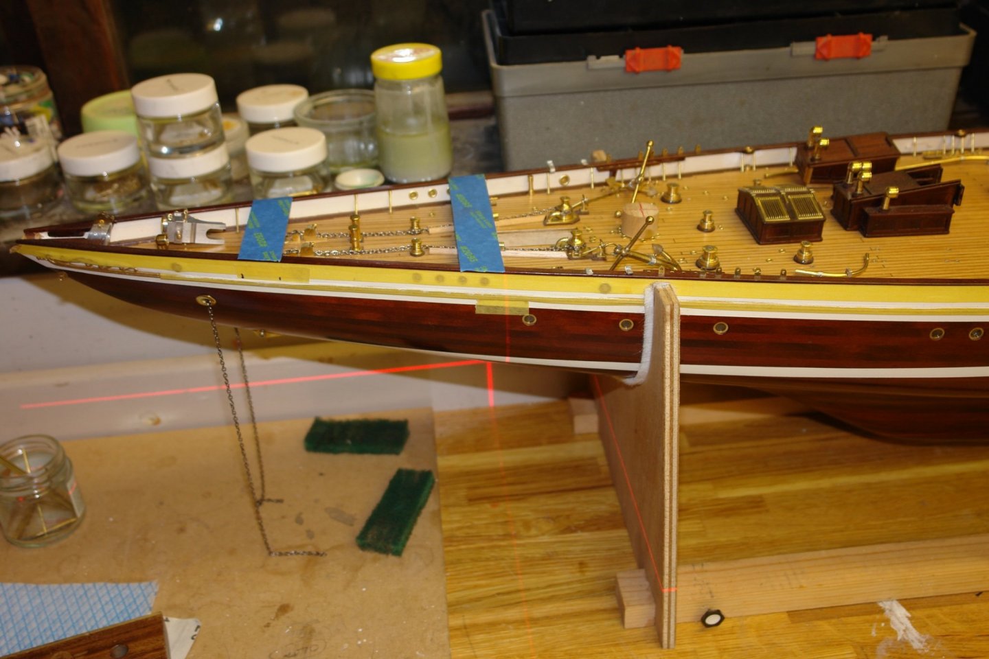
Thank you Druxey / Michael. Also thanks to everyone for the likes. I have been bitting around recently, Doing some of the mini jobs I missed out on the journey so far. On the bulwarks 12 belaying pins are mounted, I toyed with the ideal of ignoring them but in the end I couldn't. They are not terribly obvious and I guess most casual observers will miss them. I had also missed a number of eyebolts on the jib mountings (annoying to make when setting up to do just a few). I then moved on to stepping the masts - always a bit tricky to get the verticality and rake spot on. Before installing the deck I had glued an extension to the keel to create a "tenon" to accept the mast foot. I had intended slotting the bottom of the mast but in the end went for a more sophisticated solution. I turned a piece of dowel to fit the hole in the deck and into the end of this machined an oversized slot to fit over the tenon. I drilled an axial hole through the dowel and into this fixed a .312" brass rod of some 15 inch long. I then levelled the hull and set up the laser level to get the vertical. I then shimmed the slot with offcuts until I got the athwartship verticality correct. This achieved I marked the rake on the workshop wall and sighted against this line to set the rake angle. Adjusting the rake was simple as the slot was able to slide on the tenon. I applied wood glue to the slot and this gave me plenty of time to tune the rake angle. The whole exercise was then repeated for the second mast.


-
Dove by jlefever - 1:48 - Pinky Schooner
KeithAug replied to jlefever's topic in - Build logs for subjects built 1851 - 1900
The sweep of the hull is very attractive. Nice job so far. -
That is excellent news. The longest we were parted from the kids was 3 months which felt like eternity. Have a great time.
-
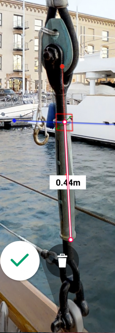
Jon - interestingly in my recent post I was also making turnbuckles - and quite similar to yours. Hull looking very sleek
-
Ras - for future reference Pritt Stick works well and removal is easy. Interesting model which I will follow with interest.
-
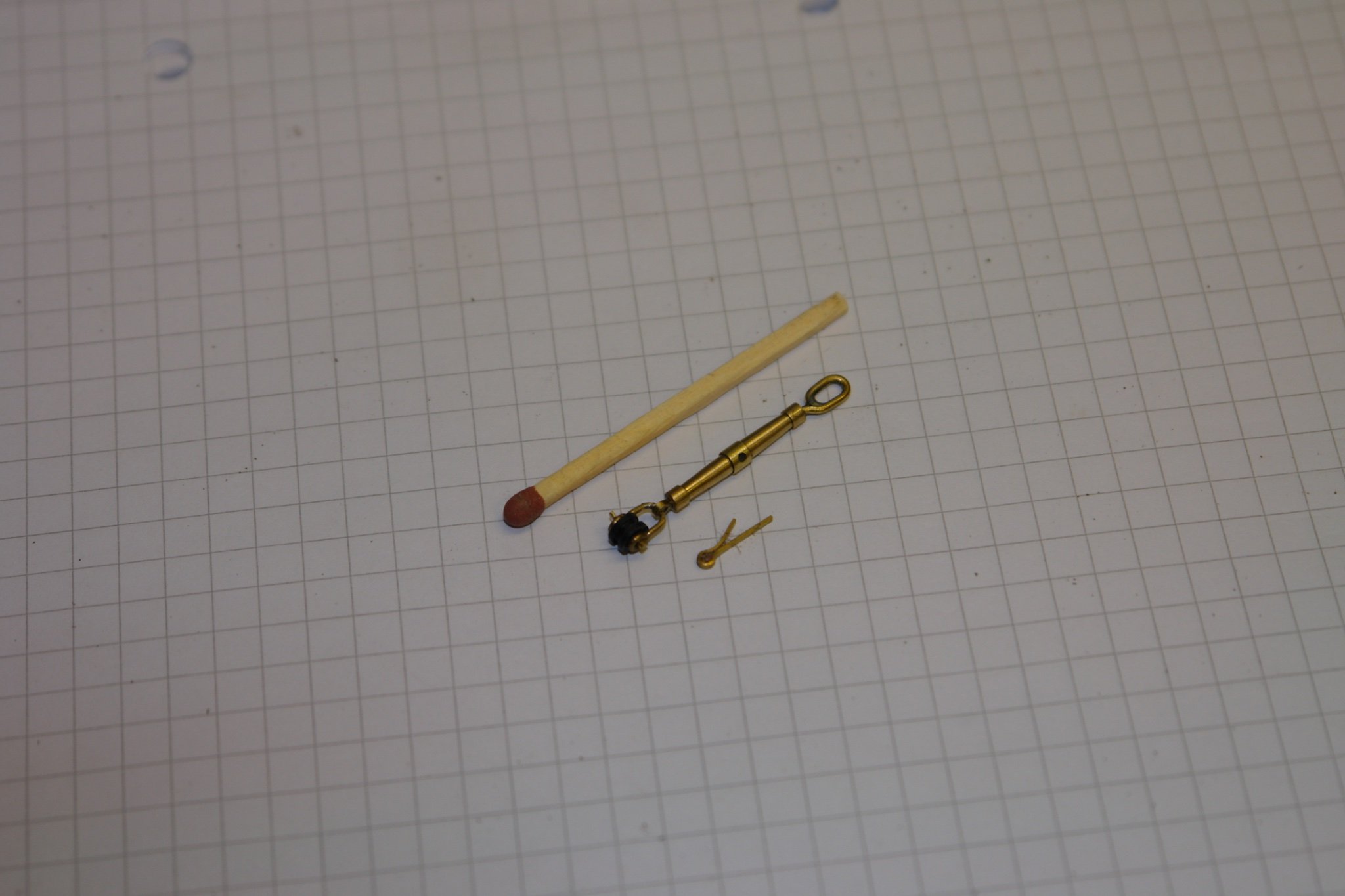
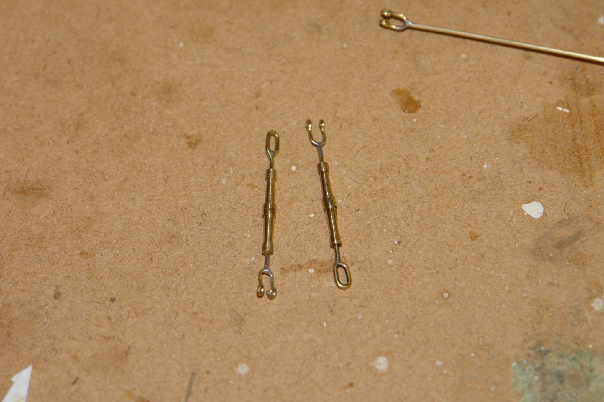
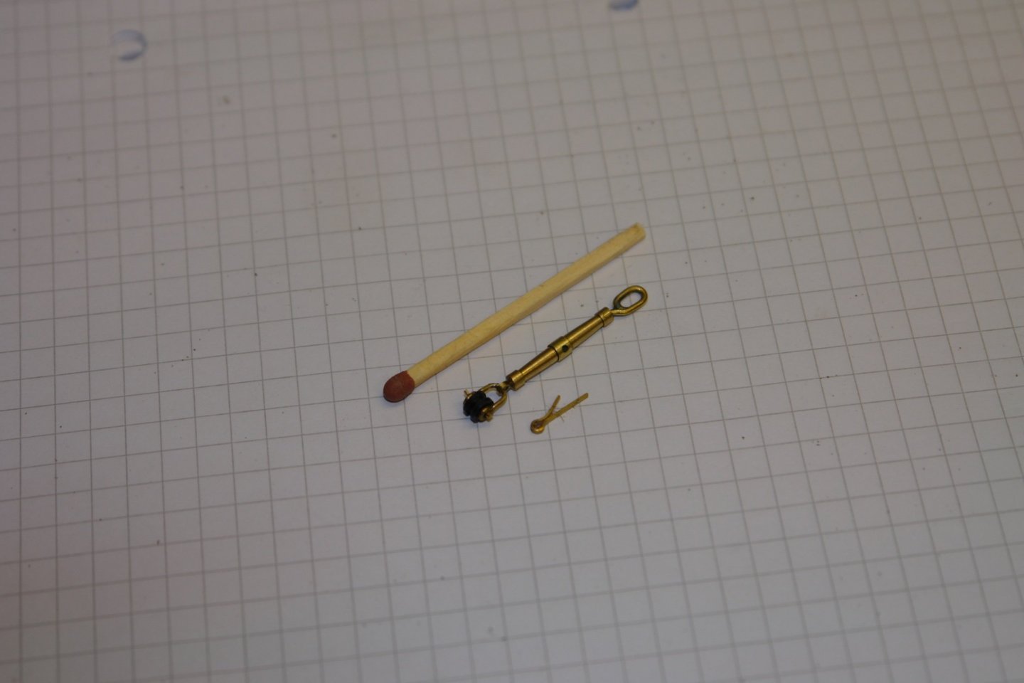
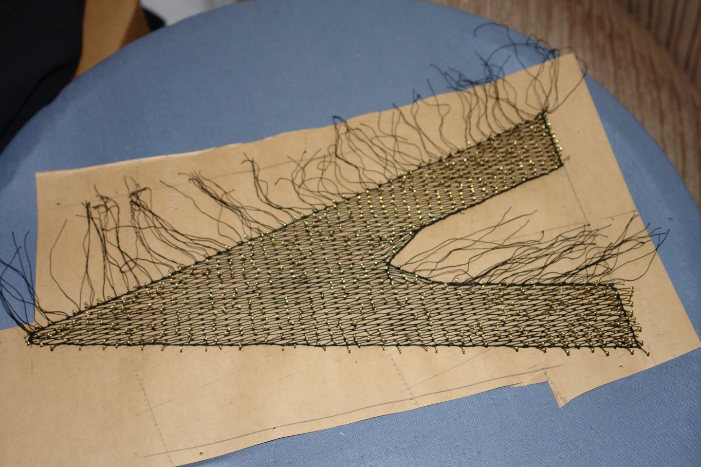
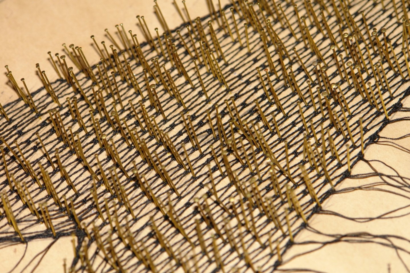
A quick update. I solved the "U" bracket attachment problem with some small split pins that i had in my bits box. They are made from .040" x .020" rectangular strip. I inserted the "U" bracket into the eye of the pin and then filed off the corners of the legs so they would fit in the .040" bore of the turnbuckle. I glued the legs into the bore and it is now much stronger. My wife finished the netting some months ago, now i just need to attach it. But not until the model is complete enough to move out of the workshop.
-
Yes Eberhard. The wire is quite thin (.031") and would melt if I tried silver solder. I thought it might work but the few pounds of tension on the stays was too much for it. However i do have a fallback plan. Thank you John.
-
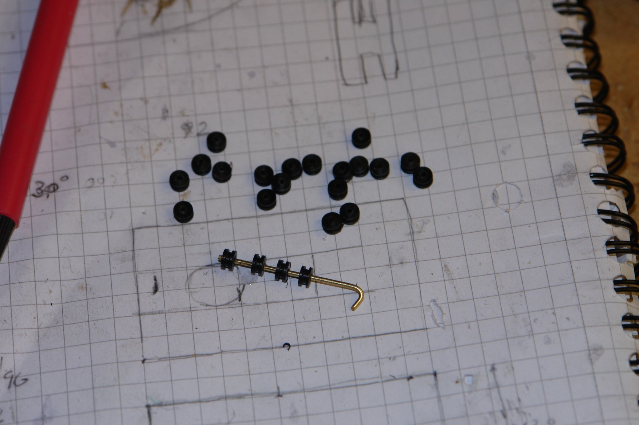
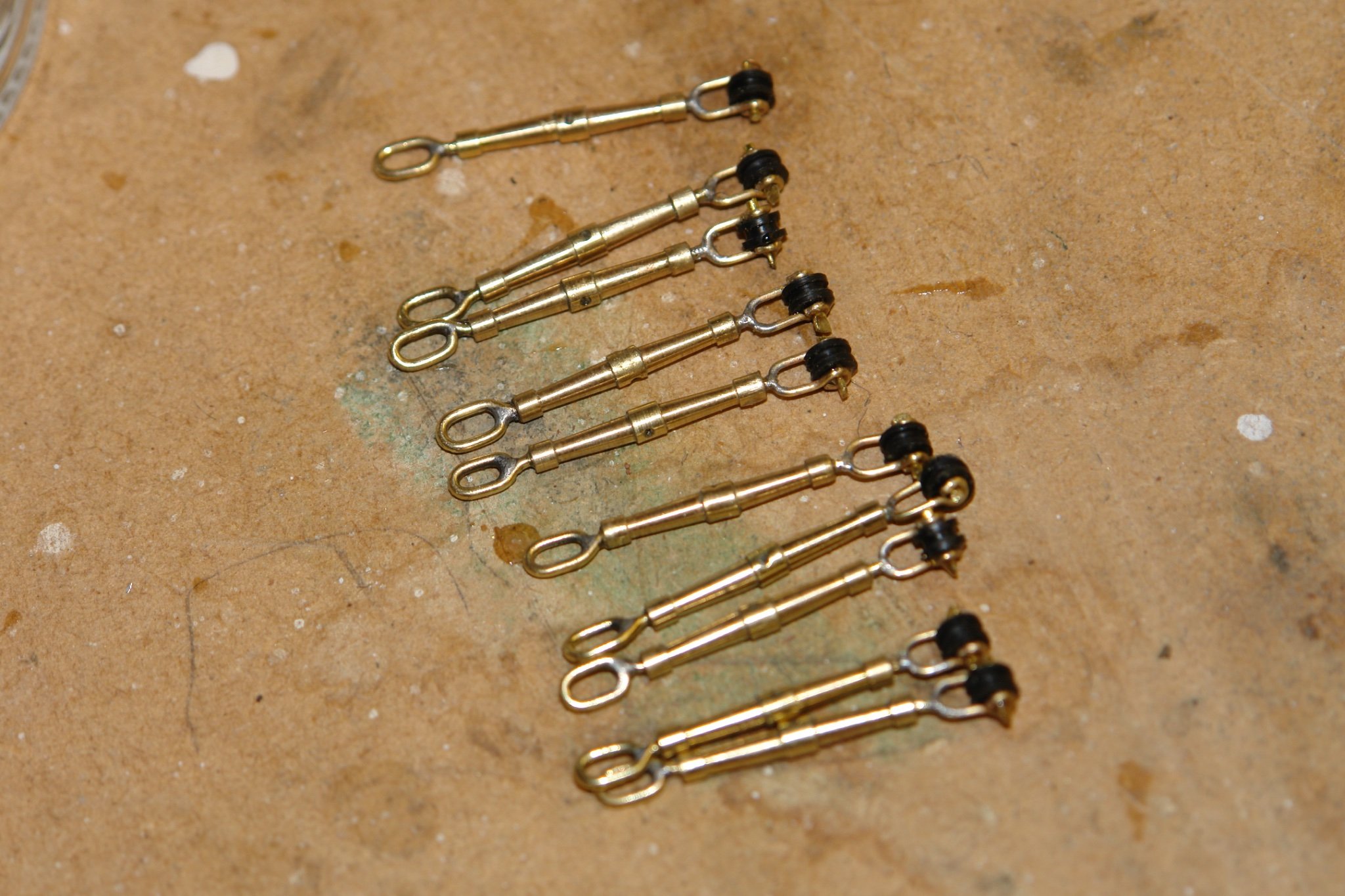
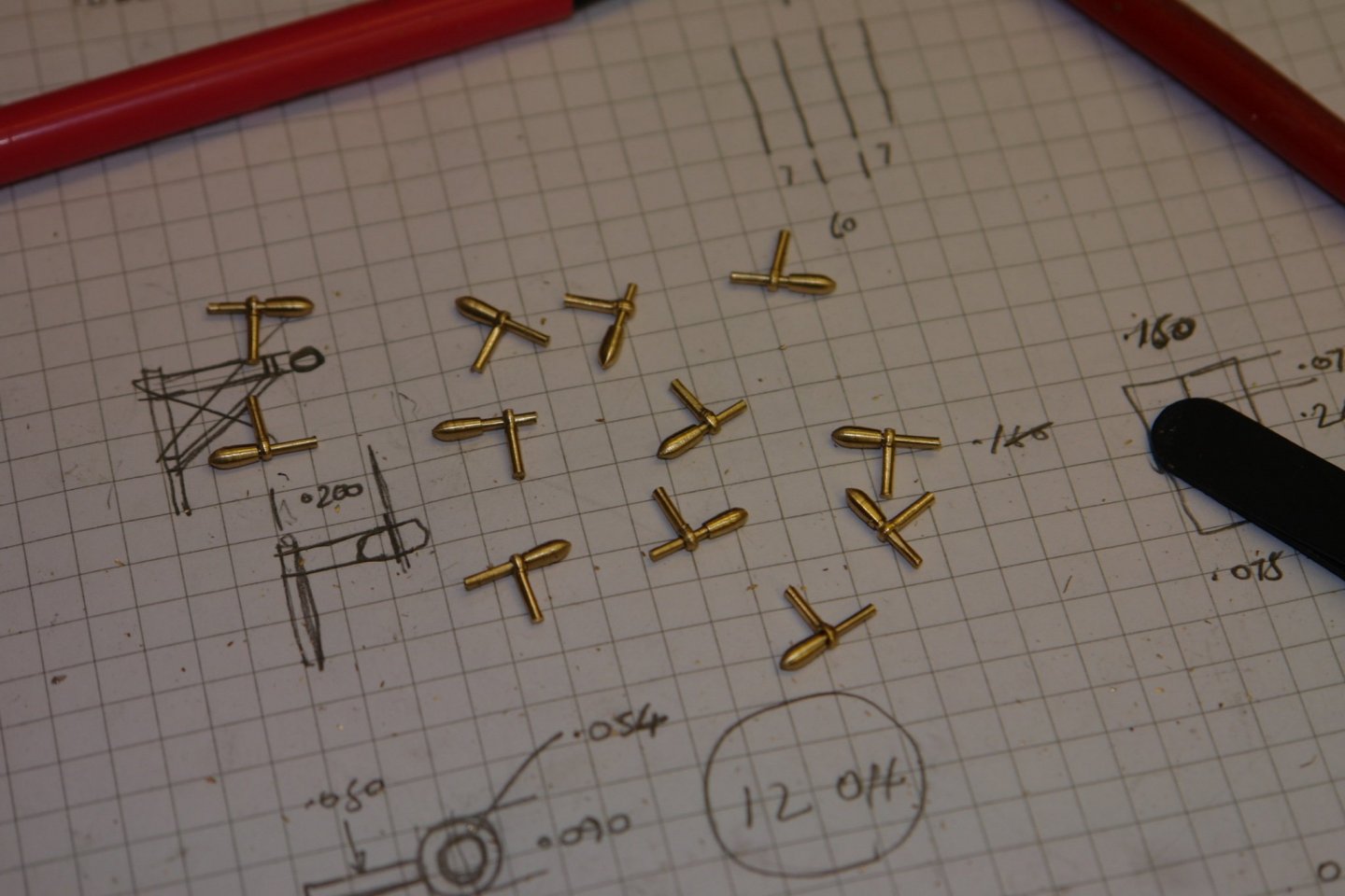
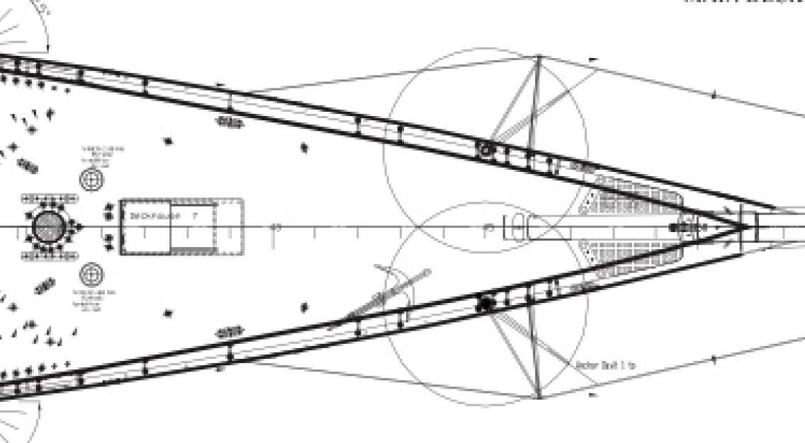
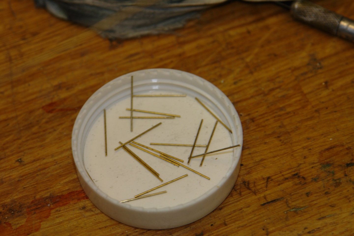
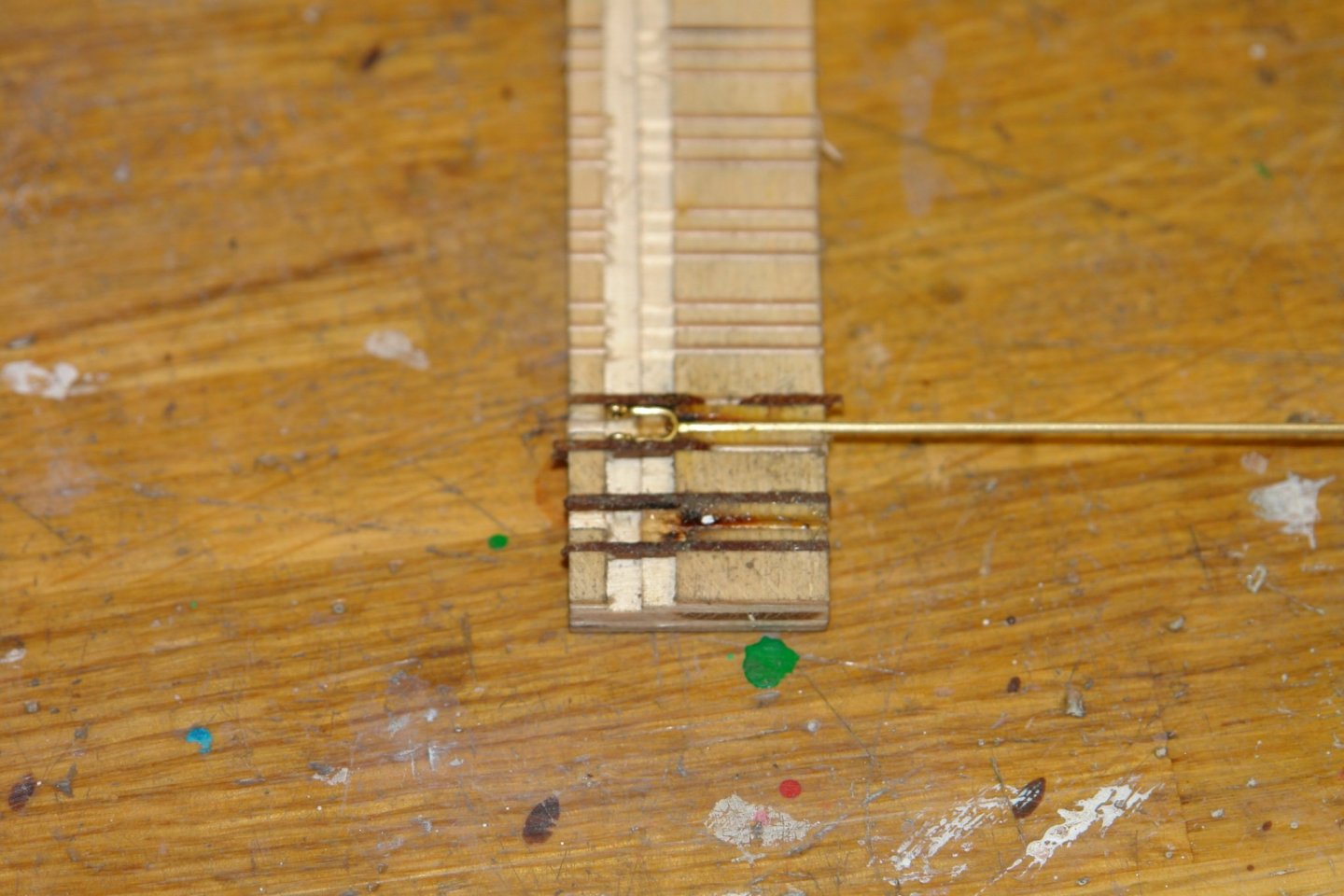
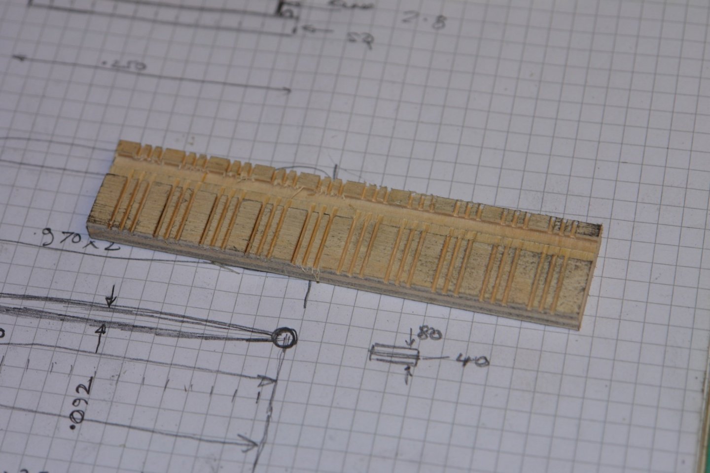
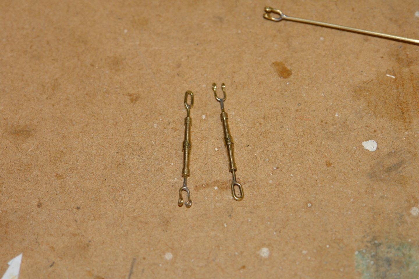
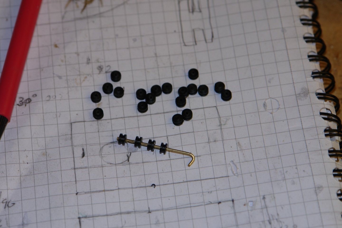
Thank you all for your comments and welcome, its good to be back among friends. It would have been sensible in my last post to include the drawing - in this case taken directly from the small scale plans. Having something to work from makes getting the angles correct much easier. I moved on to finishing turnbuckles as i need 3 for the bowsprit stays. Earlier (page 51) I had made the turnbuckles without completing the "U" shaped end. I made the ends out of wire - each piece cut accurately to length using a jig. The "U" shaped end was bent up by eye but i needed a jig to assist when soldering the "U" to the stem. The "U" end holds the boss around which the stay passes, these were machined from plastic rod. Followed by assembly. Unfortunately this wasn't the end of the exercise. I installed one and broke it when tensioning the stay. The solder joint between the "U" and the stem failed so I am going to have to rethink this connection.

-
Beautiful work on the blocks Eberhard - just thinking about them hurts my eyes. I liked the lathe saw attachment - i may do something similar one day.
-
it is all rather beautifully done Brian. Obviously you like the pristine look, as do I. My guess is that the original was rather more rustic, even in its as new condition. What do you think?
-
Certainly one of the most unusual ship models I have ever seen ( and very nicely executed) . Moving round the harbour in a stiff breeze must have been a truly interesting experience.
-
The framing is looking very good and the last photo illustrates very well how good the fairing is. i am looking forward to see how the planking goes.
-
Turned out rather well Tom. The starting point was something that I think might have graced my wood burner, just goes to show how wrong first impressions can be.
-
Valeriy - such wonderful work - I think you may be making your parts look better than the originals.
-
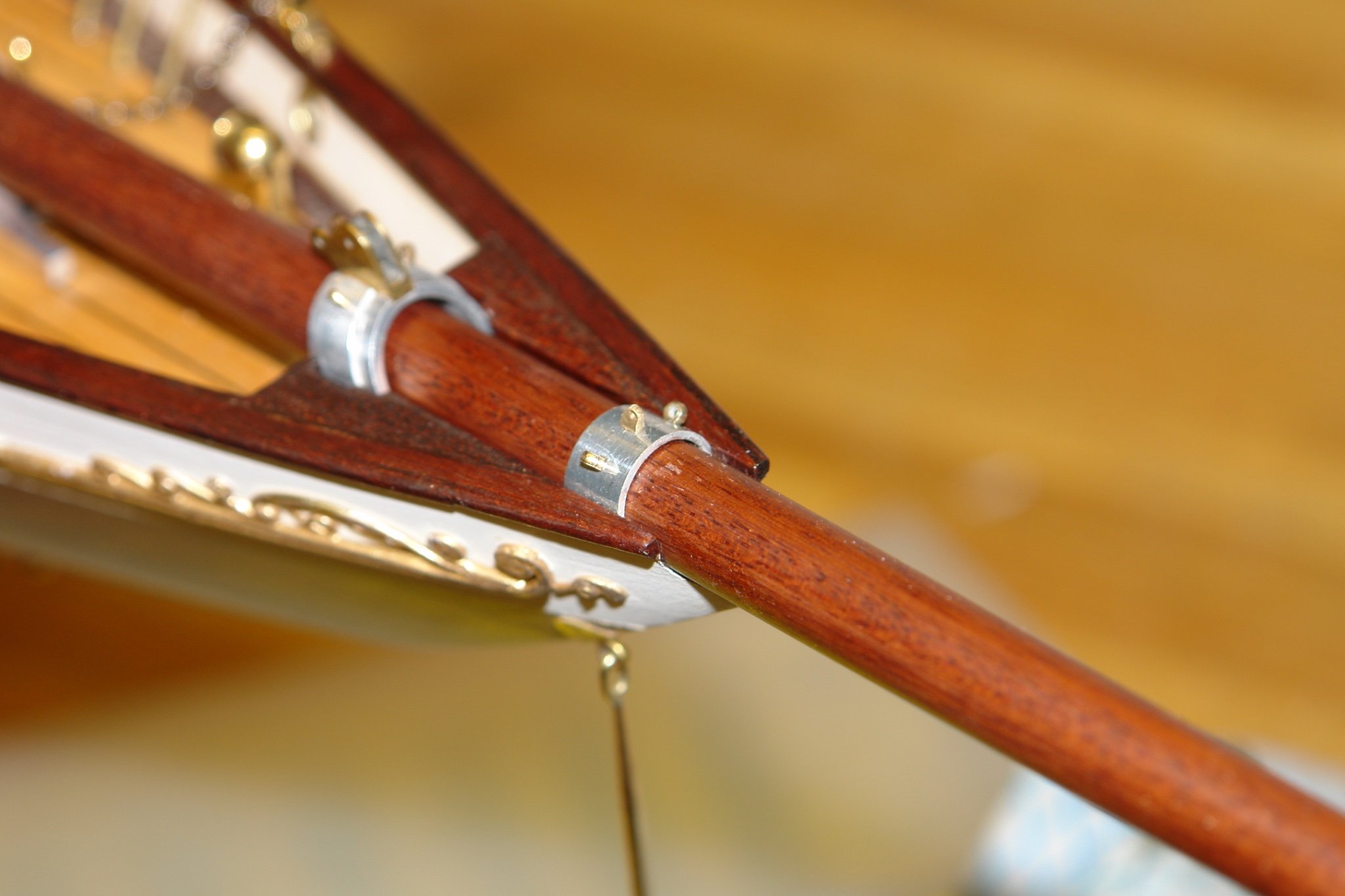
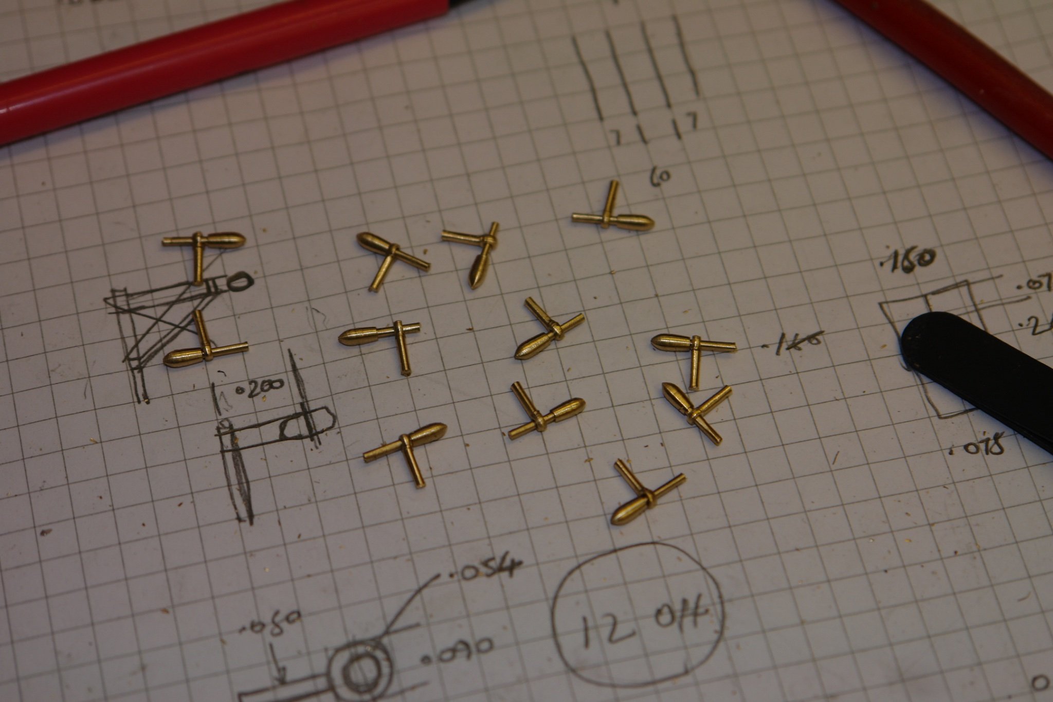
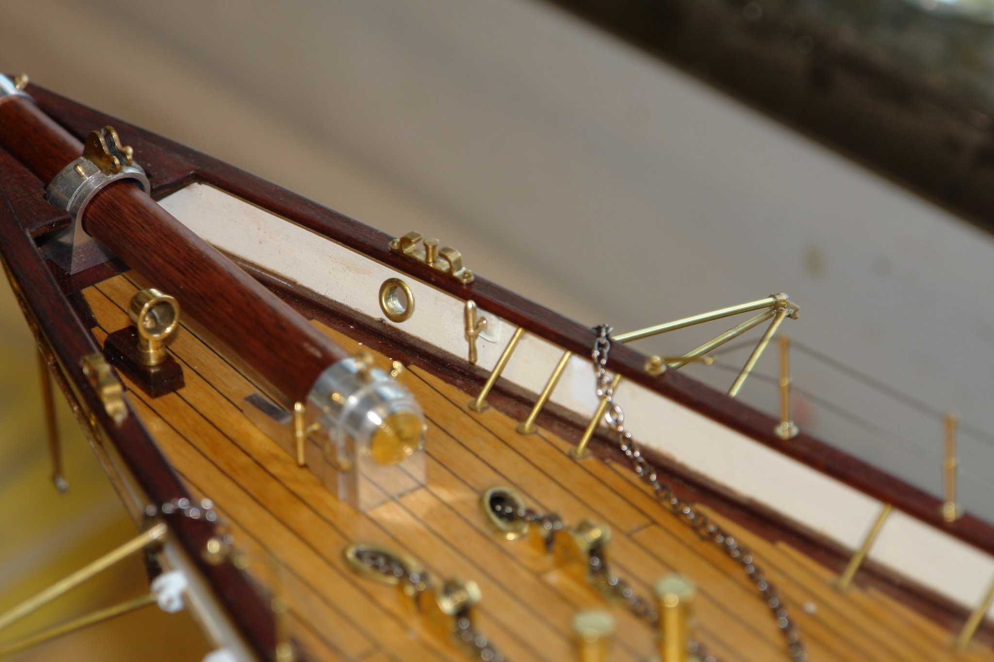
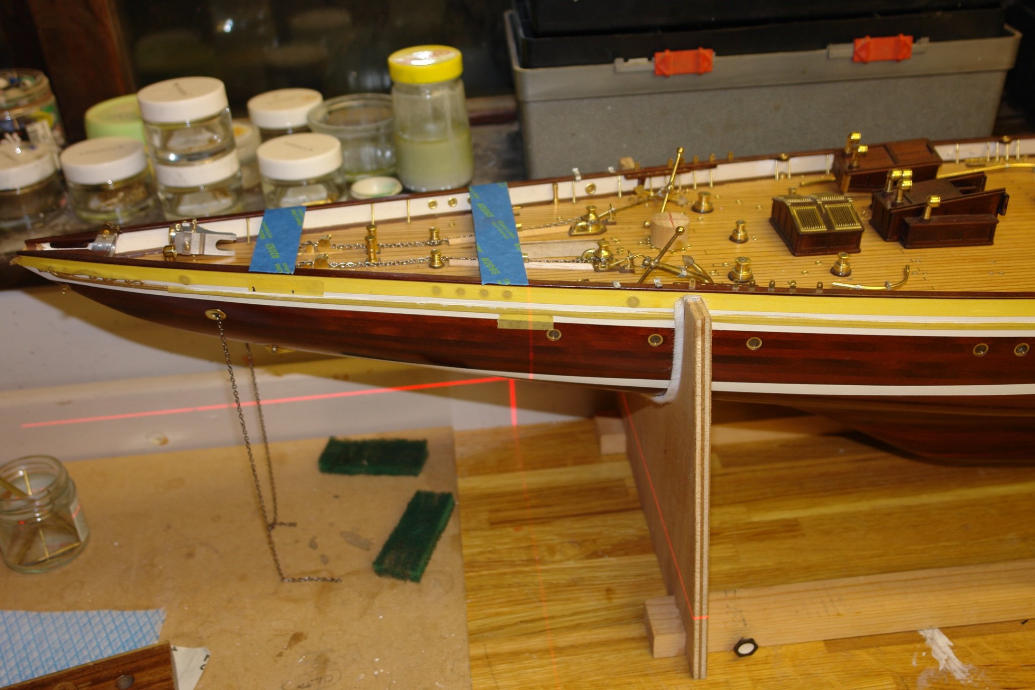
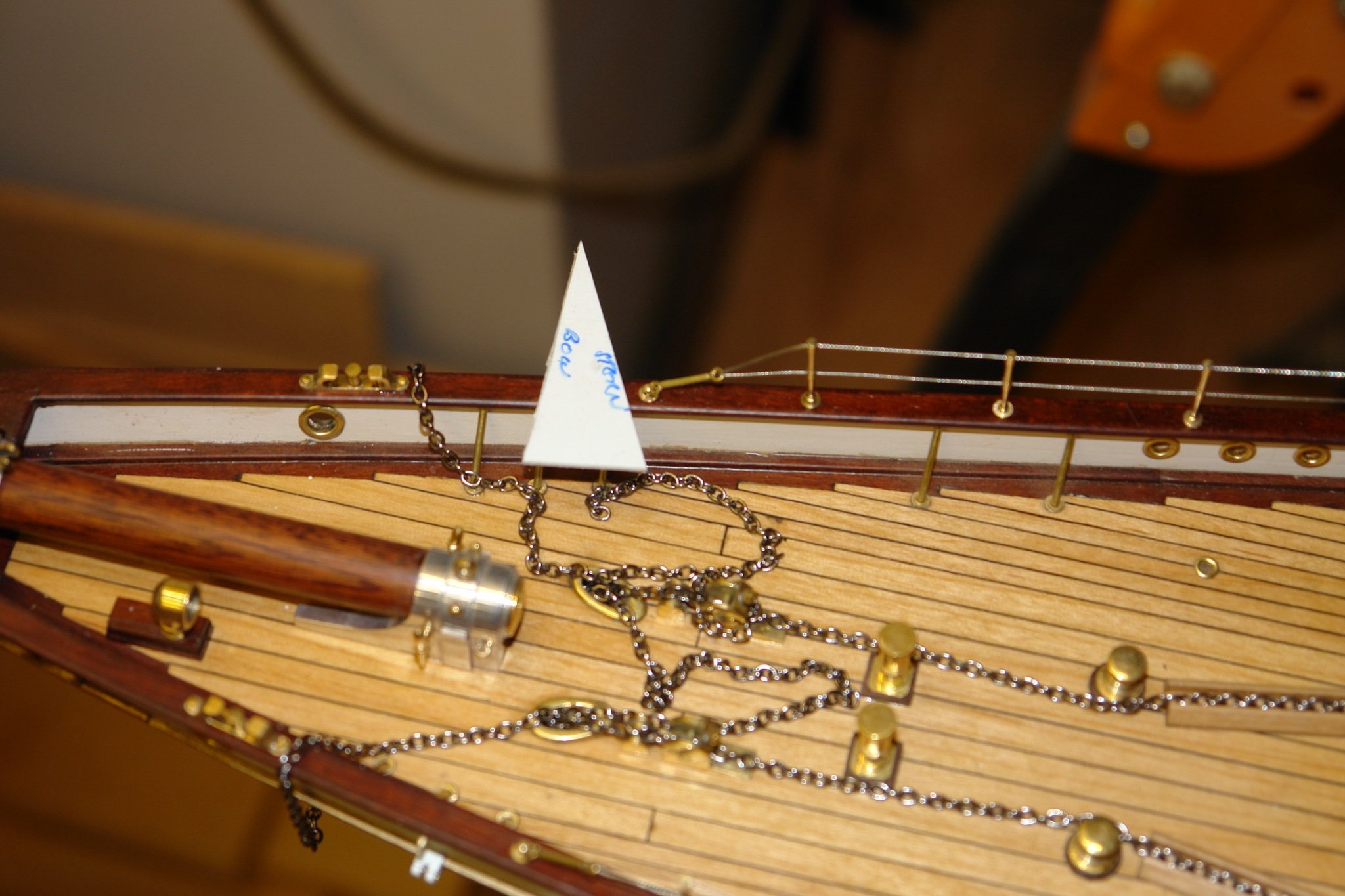
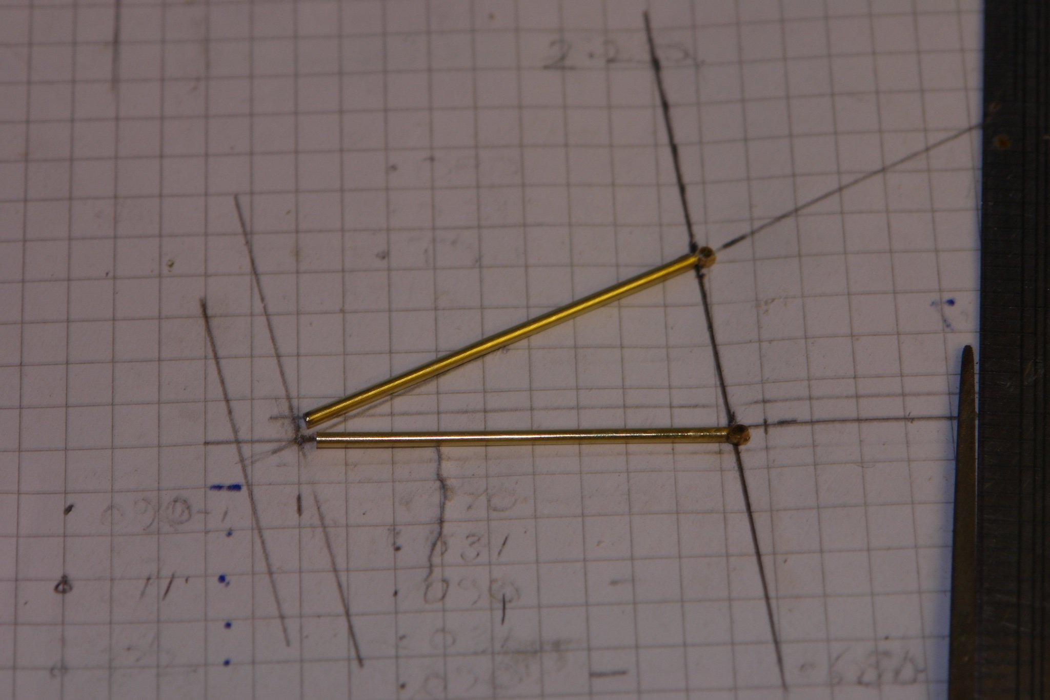
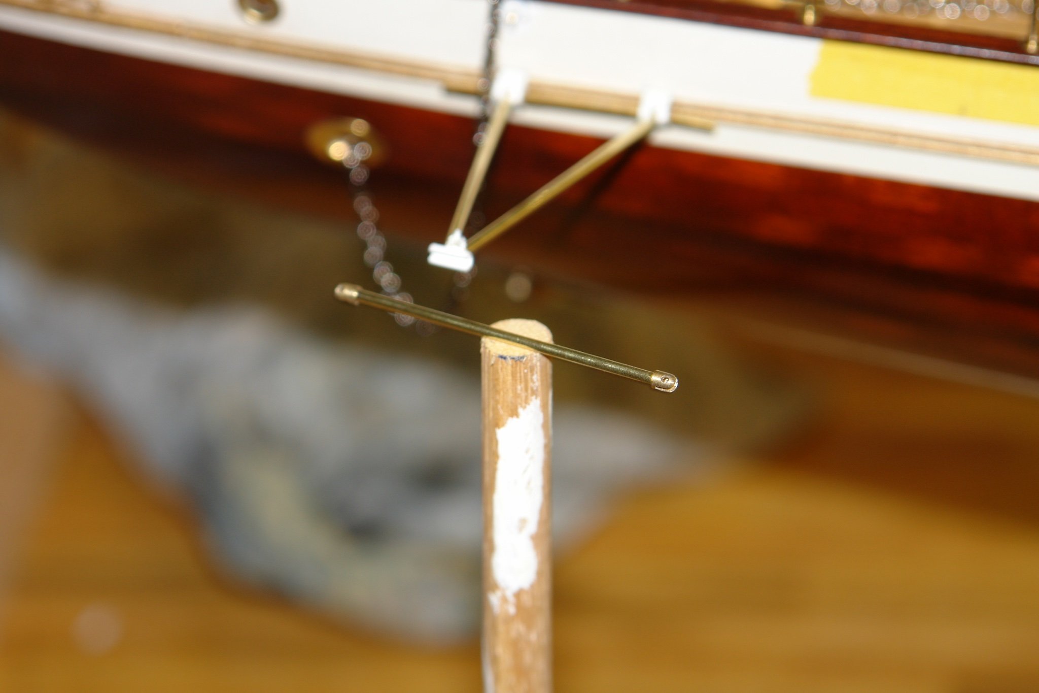
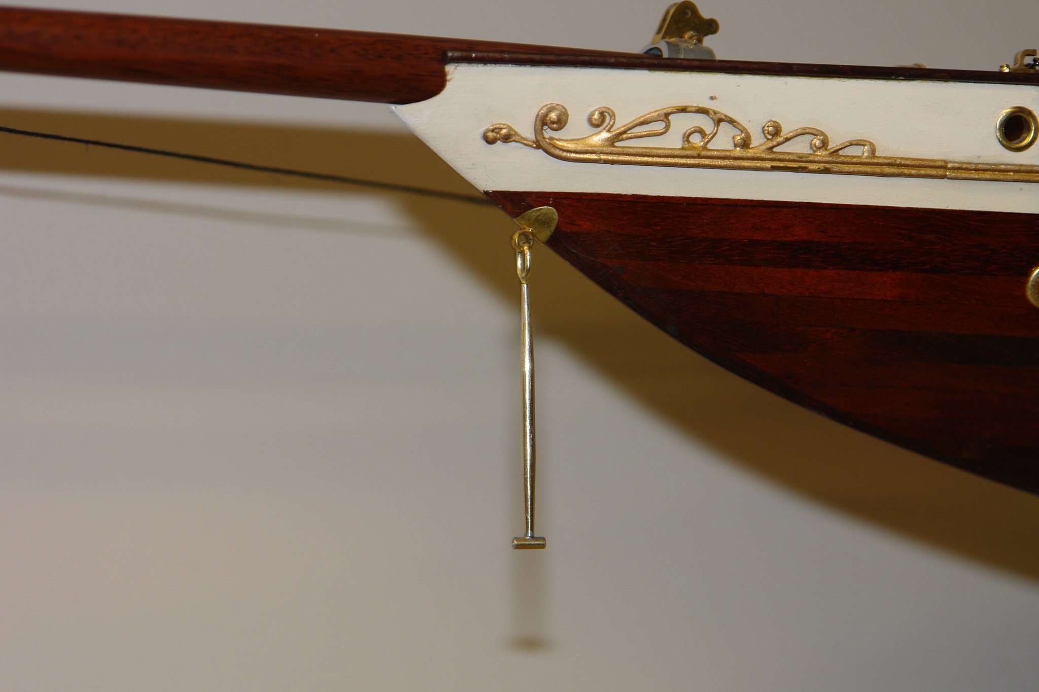
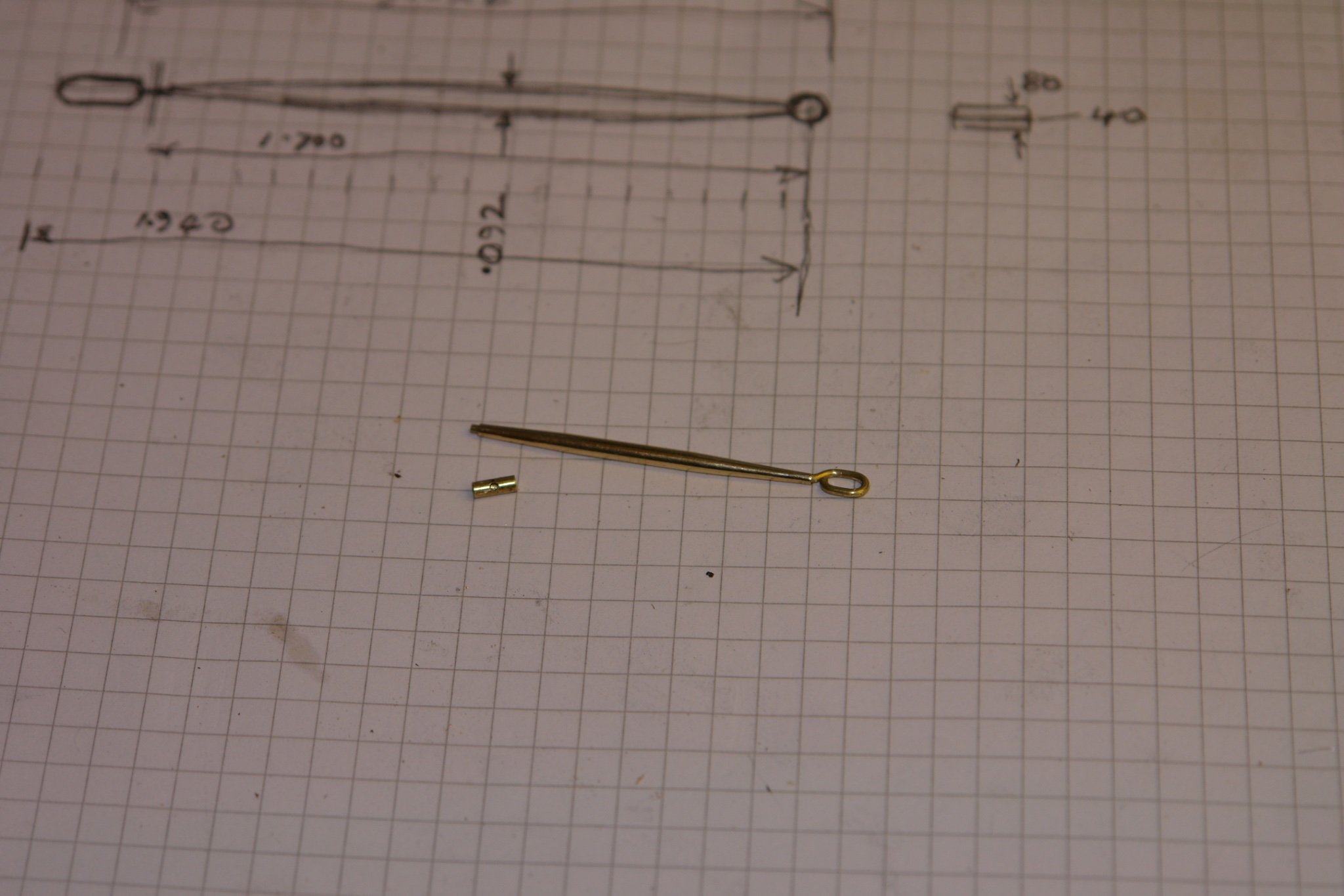
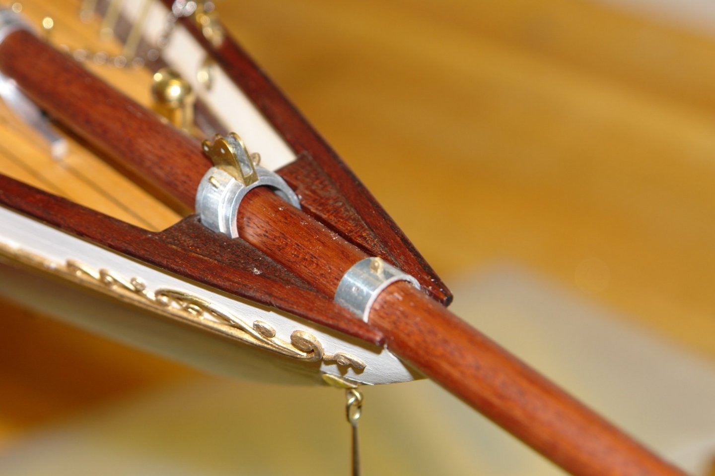
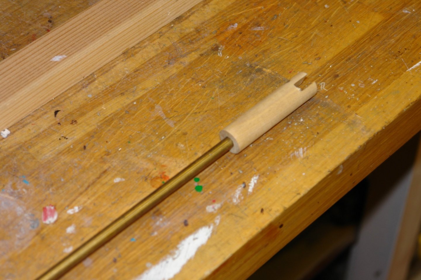
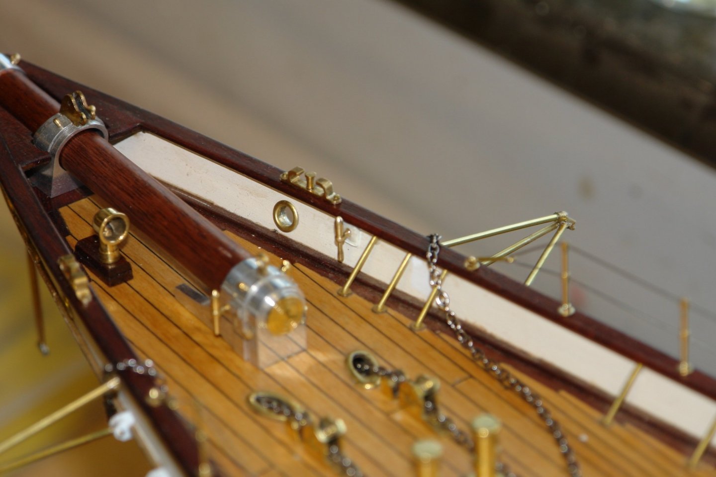
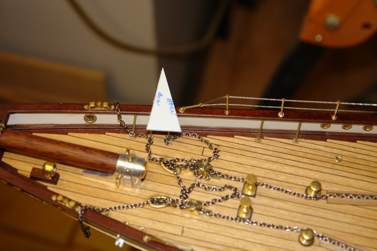
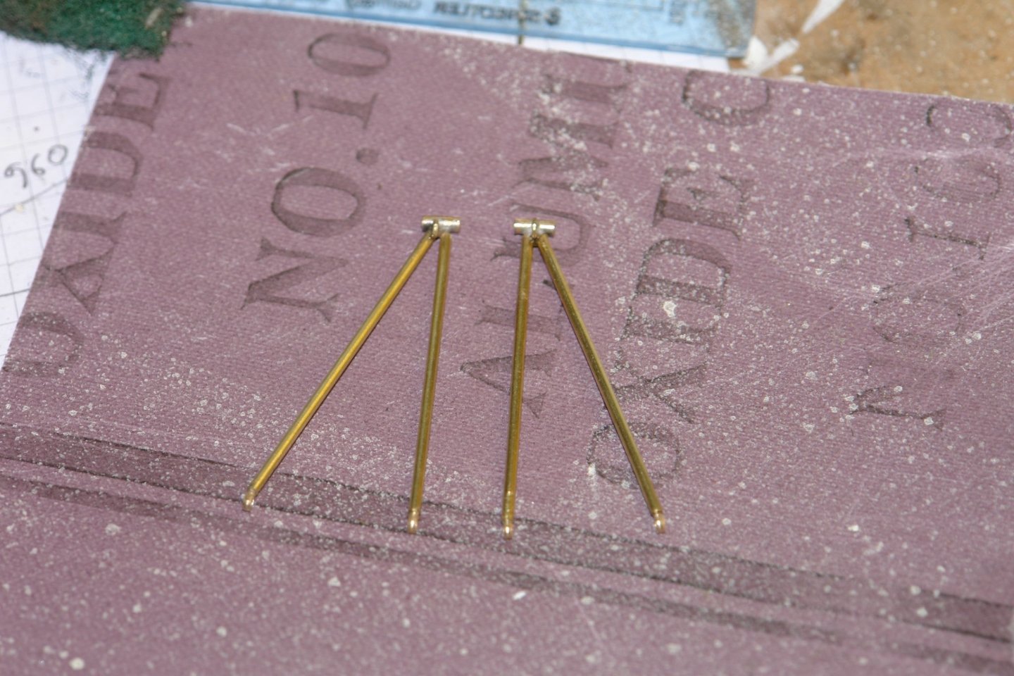
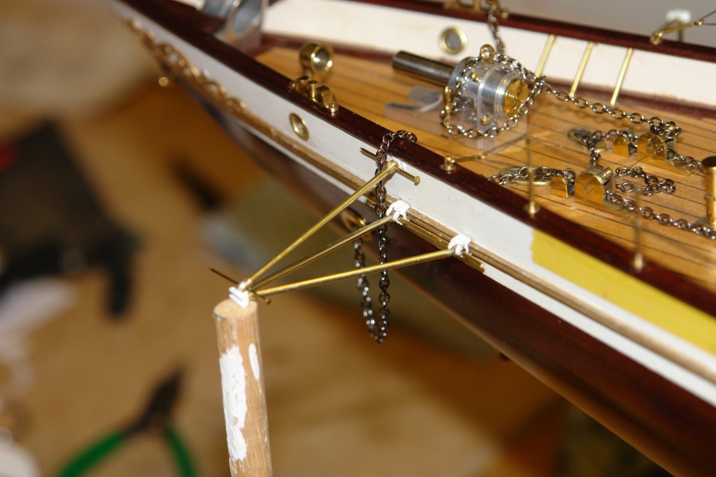
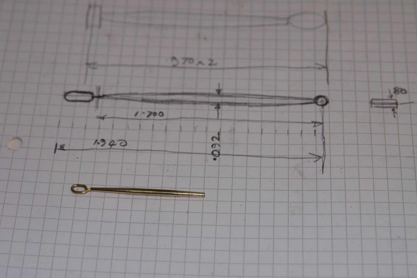
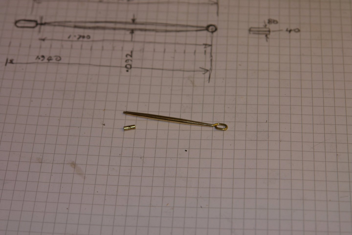
Well that was a long summer shipyard shut down. I sort of got distracted into reconnecting with family and friends and that together with a backlog of outdoor tasks kept me out of the workshop. While summer continues to hang on the days are starting to feel a bit autumnal and the winter building season has therefore opened. I recommenced by sorting out the jib stay outriggers. I cut a card triangle to the plan shape of the outrigger and marked up the hull position using a laser level. I transferred the outrigger shape to paper and used this to size the struts and get the angle correct. The soldering job was a bit better than the last effort. I glued the outrigger mounting brackets to the hull in the previously marked positions. To get the outriggers mounted horizontally I made an end support from a piece of dowel. I then sized the top arm of the tripod to maintain the correct angle of the outrigger. The bracket which holds the aft end of the jib stay to the hull was then mounted. Small pins were then turned to fasten the outriggers to the hull. To test the run of the stays I fixed a temporary line. The net job was the dolphin striker. The stem was taper turned from .093" brass rod and this in turn was soldered to a short length of tube to take the lower jib stay. The upper end loop was bent from wire and inserted into an dial hole drilled in the stem. The hoop was then attached to the hull mounted bracket (installed 2 years ago). How time flies. I now need to catch up on all your progress during my absence.


-
Beautifully done George.
-
Well worth a visit Eberhard. It was very quiet when a group of friends and I went about 15 years ago. She was in the early stages of preparation for display and a very obliging volunteer took us on a very detailed tour of the engine room -- quickly curtailed when we realised the restoration crew were hacking lumps of asbestos off the steam pipes. Clearly asbestos regulations are not always the same.
-
HMCSS Victoria 1855 by BANYAN - 1:72
KeithAug replied to BANYAN's topic in - Build logs for subjects built 1851 - 1900
All looking very smart Pat. I enjoyed magnifying the deck photos and taking a self guided tour. Nice little bell, I guess it does not have striker at that scale?- 1,021 replies
-
- 4
-

-
- gun dispatch vessel
- victoria
- (and 2 more)
-
A remarkable amount don for just a year - compared to my sometimes pedestrian progress. The hull painting turned out rather well and overall she is looking quite trim - probably a lot more so than the original. I continue to find this vessel most interesting. Condolences on the loss of your Father in Law.