KeithAug
-
Posts
3,986 -
Joined
-
Last visited
Content Type
Profiles
Forums
Gallery
Events
Everything posted by KeithAug
-
 All looking very interesting Michael, looking forward to seeing it develop.
 -
Eberhard - yes that is what I find. I am constantly out of focus because my hands naturally drift out to my normal working distance.
-
Eberhard - today I forced myself to use the Optivisor and remembered why I hated it so much. I admire your dedication and skill but I think I will stick to larger scales. great work and usual.
-
Geert, thank you for the explanation of colouring the sails. I lean something new every day.
-
Mark - You even made the news over here. I always think bread a butter construction is a hard trick to pull off but the hull shape turned out quite pleasing.
-
I think that the beaten up nature of the engine makes it more endearing but shouldn't the pallet be stained with oil? Noting how knackered the engine looks surely the odd seal or two should have gone?
-
Vaddoc - Exceptional dedication to planking. Are you intent on burying all this hard work under paint?
-
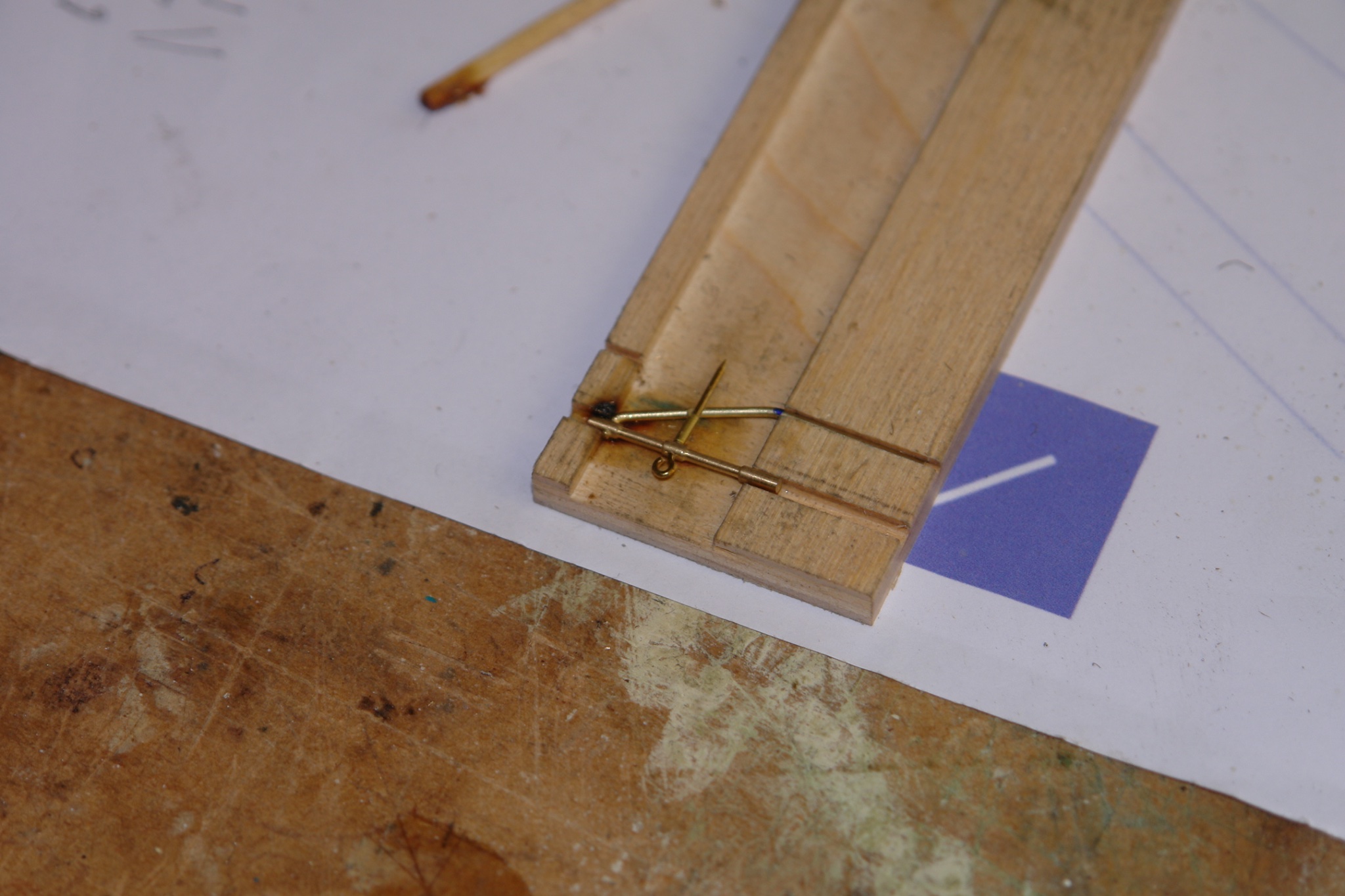
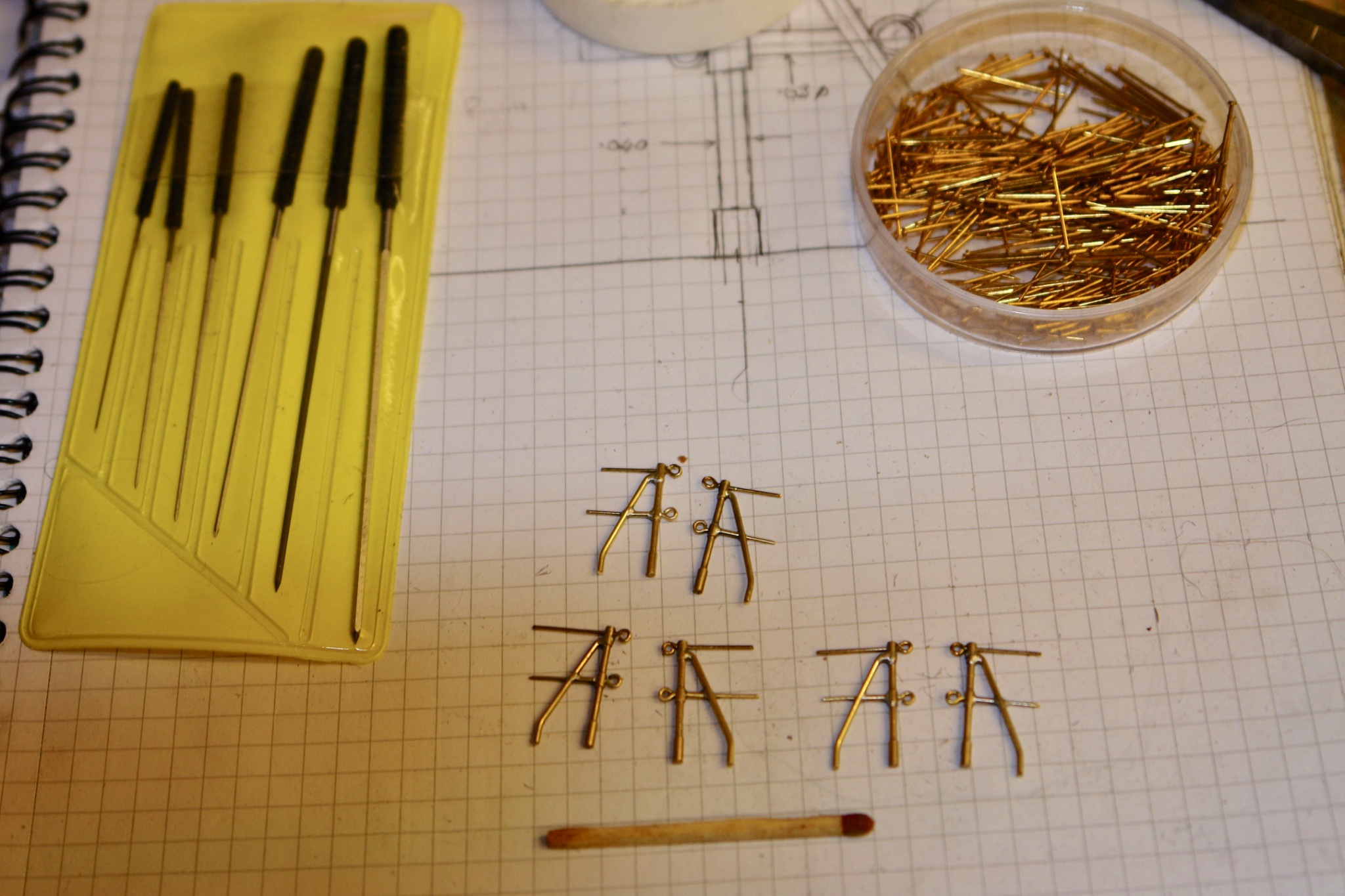
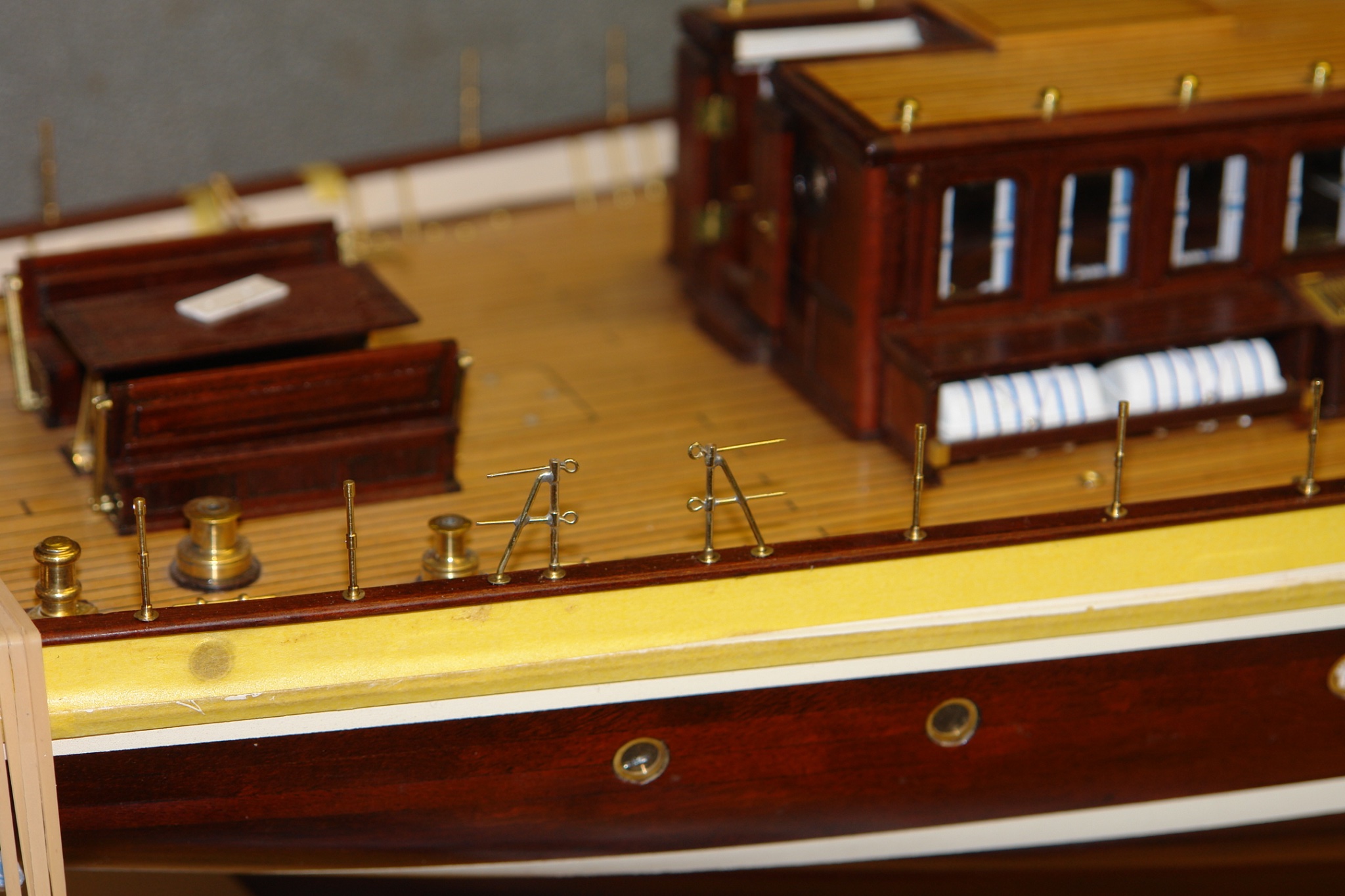
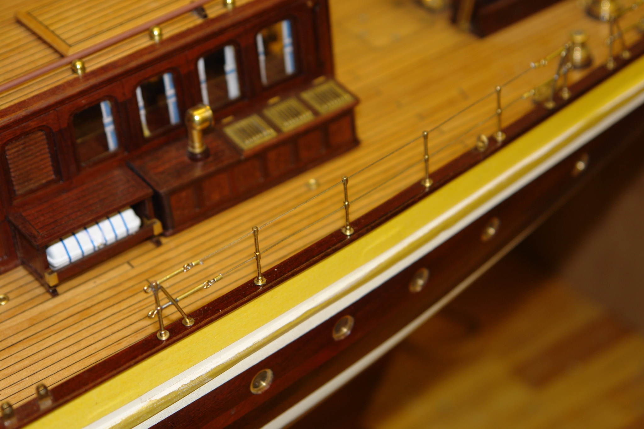
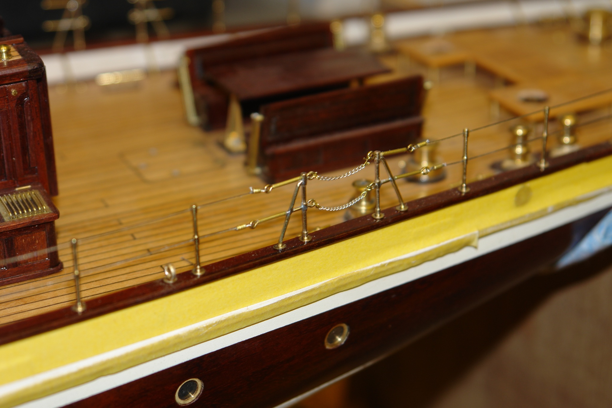
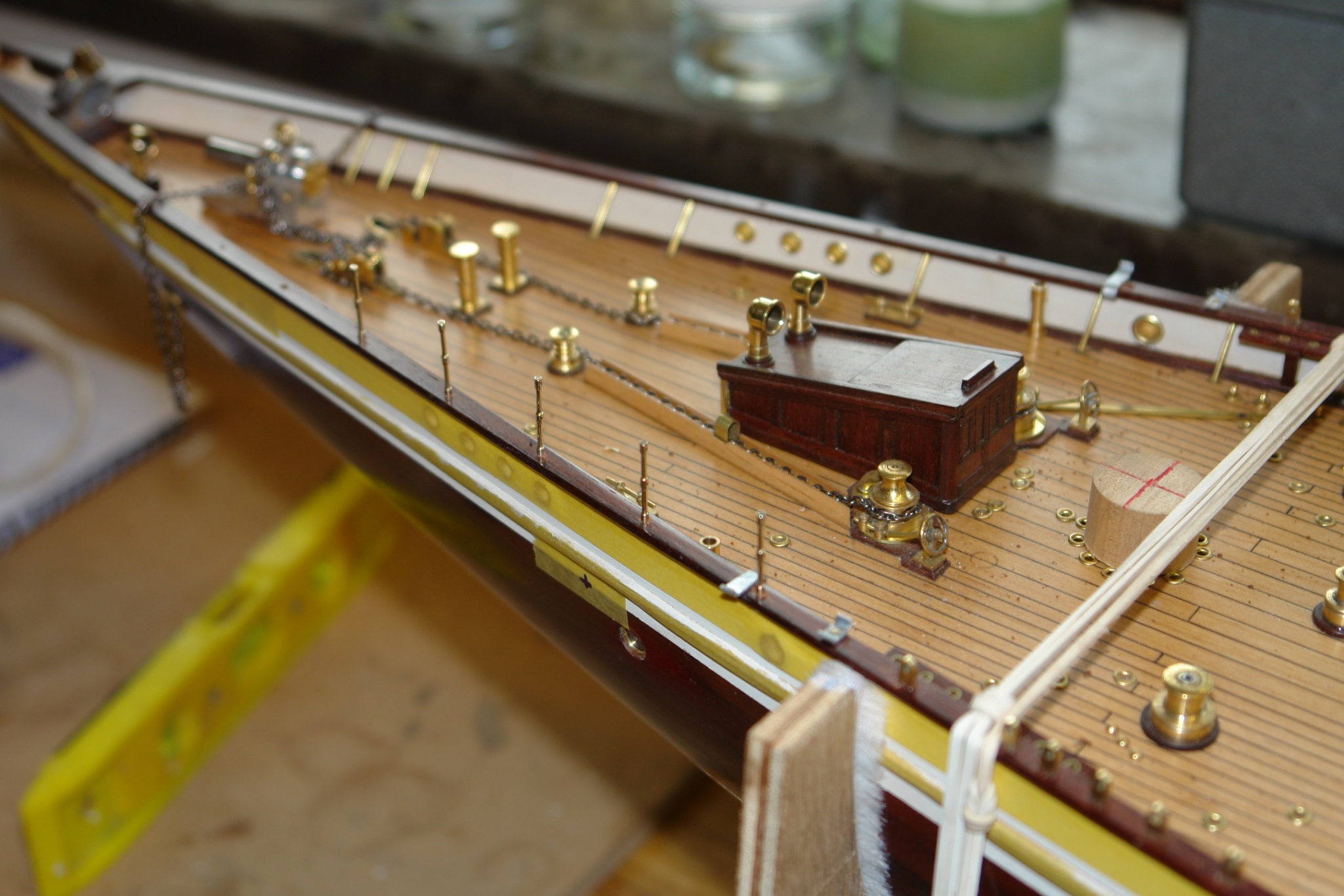
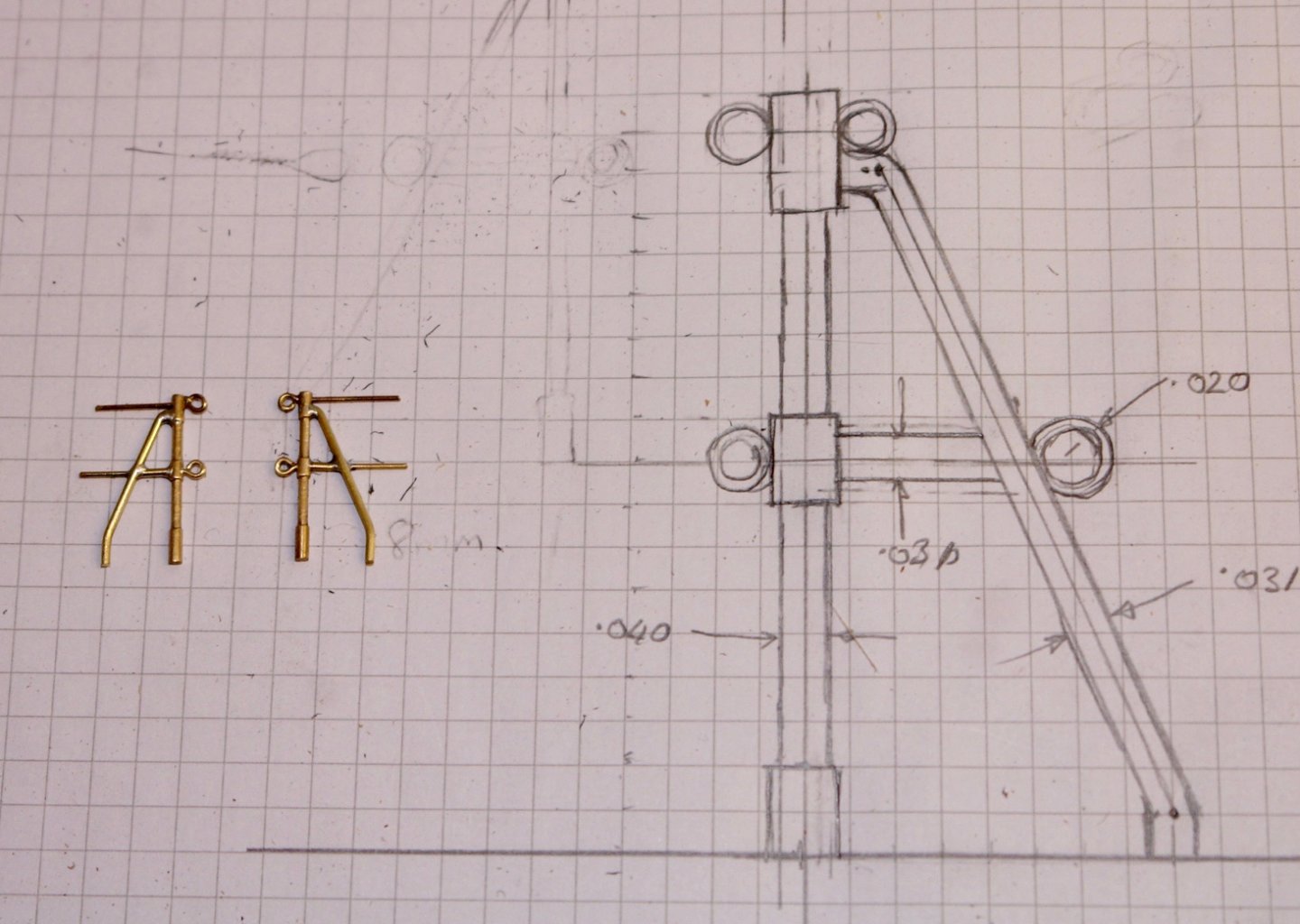
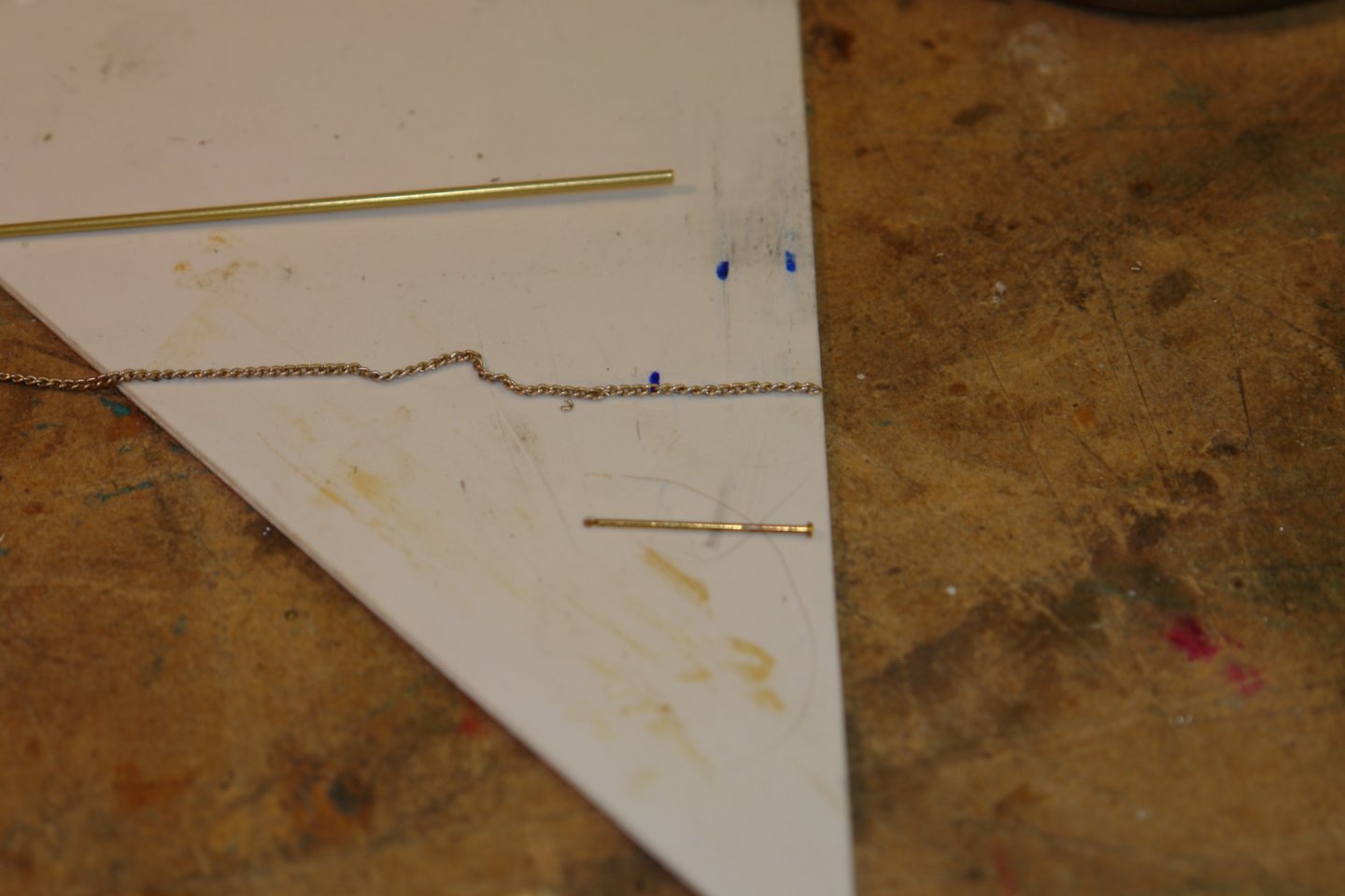
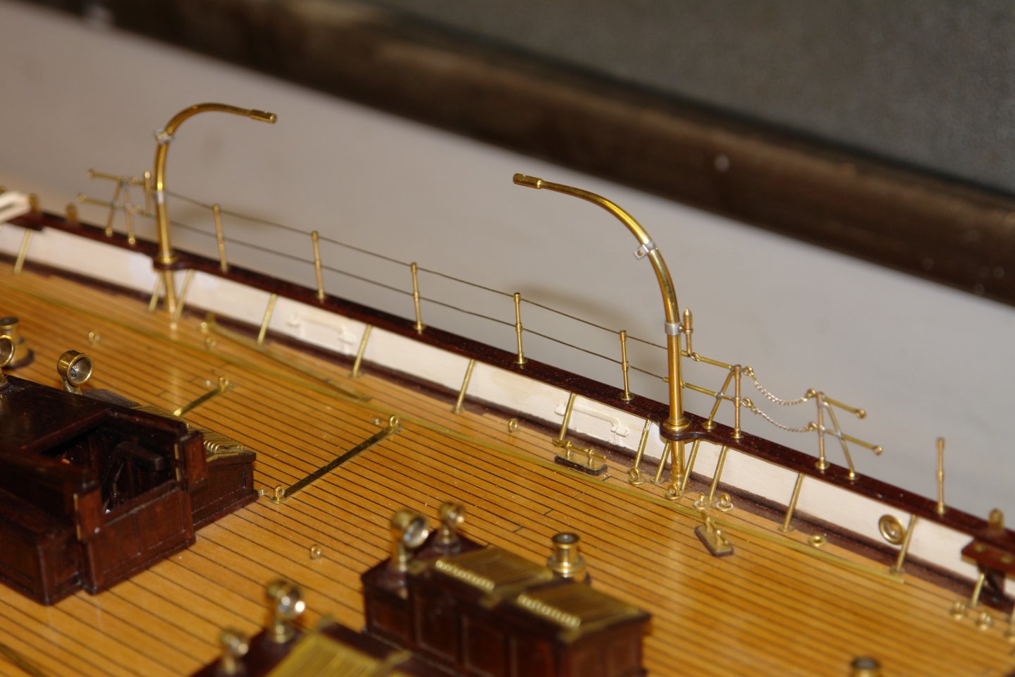
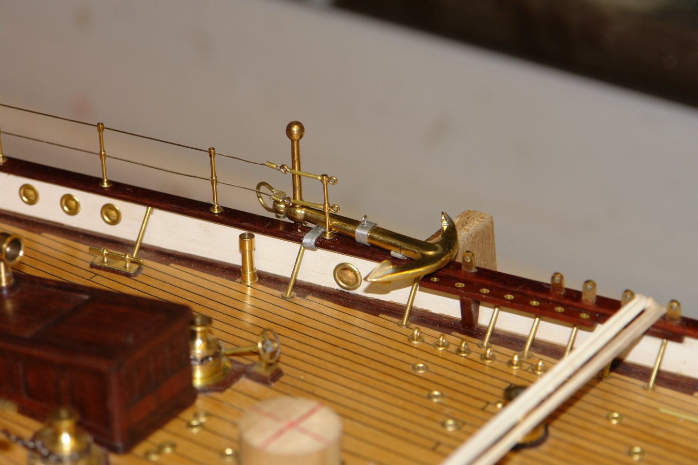
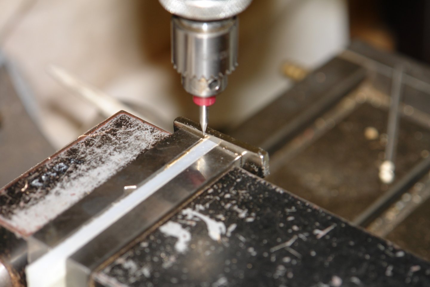
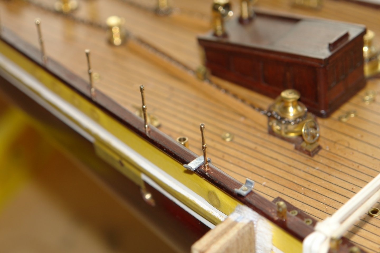
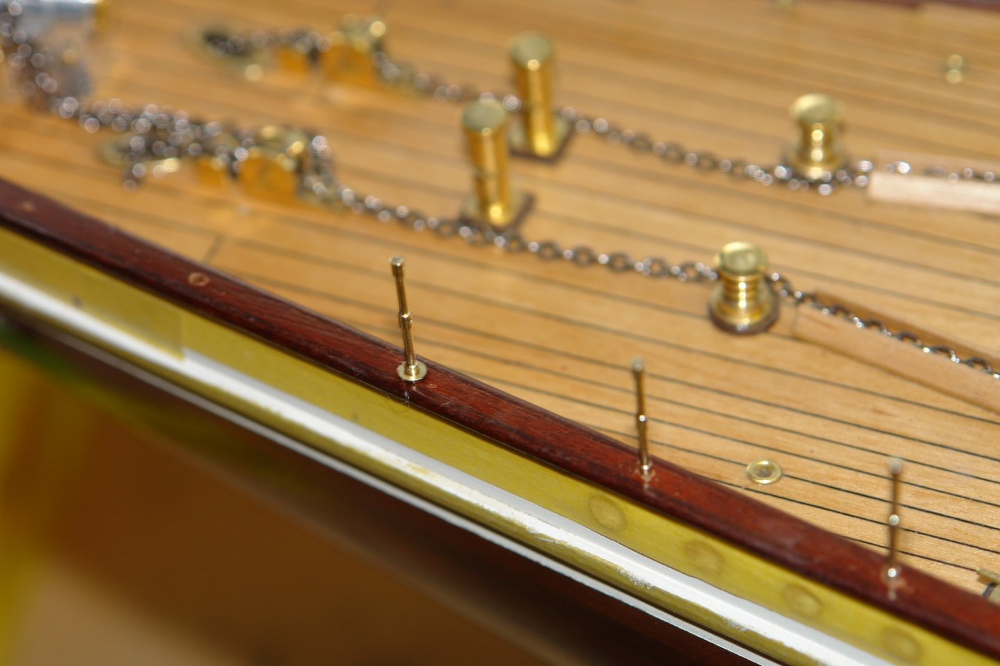
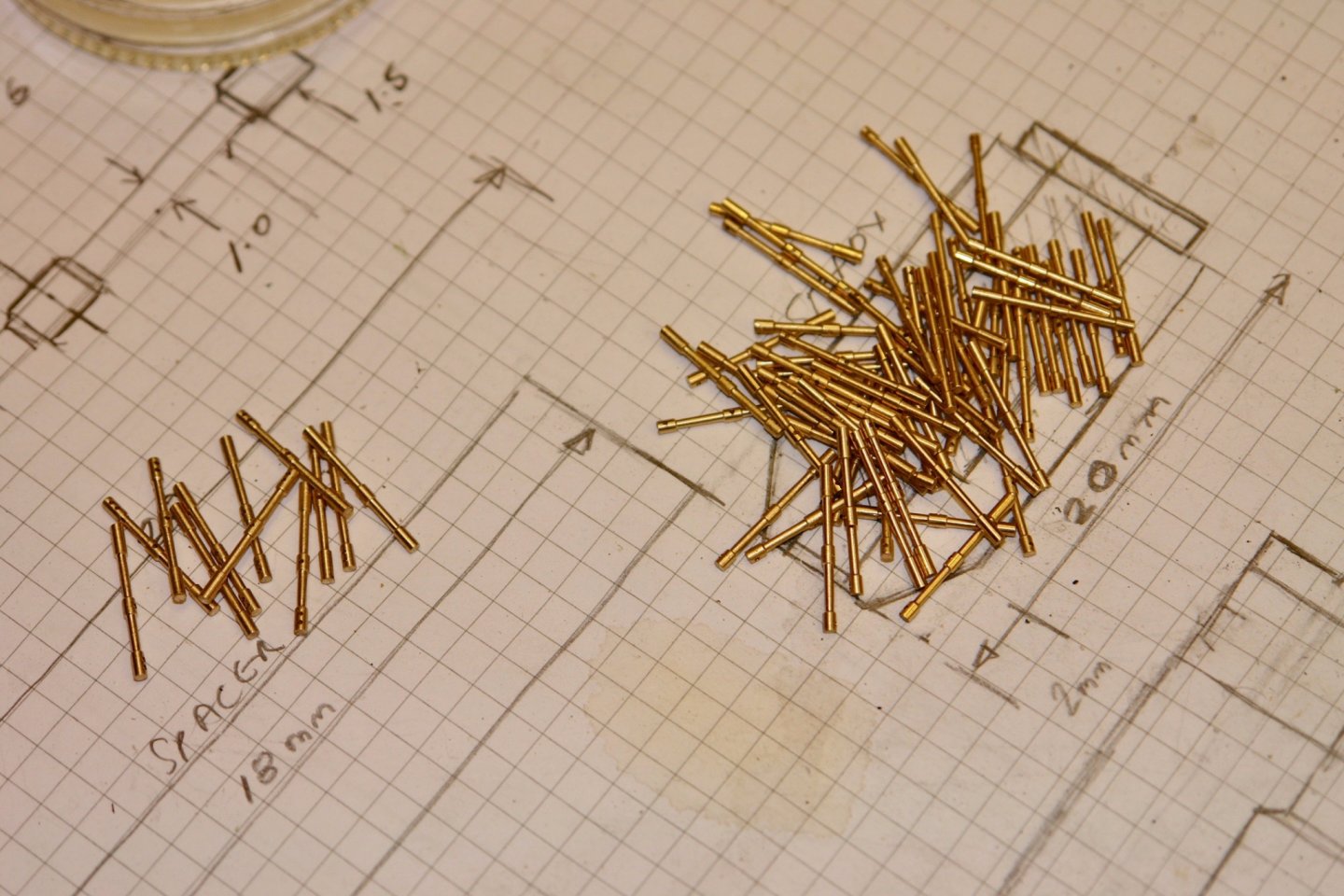
Druxey - more laborious than nerve wracking. I think the professionally made ones are very expensive but I can see why. At a number of positions the stanchions have a bracing strut - hence the third hole in some of them. The drawing is a guide rather than exactly what I made. A couple of experimental ones are displayed in the photo. I figured that to get them identical I needed a jig. I had a fair number to make, 12 in all. They are 0.6" high. I needed to accurately space the holes in the rail so I made myself a little drill guide. As per the other stanchions the braced ones were pressed in to slightly undersized holes with brass washers at their base held by a spot of CA glue. At the fore and aft ends of the stanchions the grand wires are attached to eyes mounted on the rails. The eyes were turned and milled as previously described. Tensioners are attached to these eyes - simulated from micro tube and wire. I used 0.017" beading wire for the guard rails. The wires were looped at the ends trough ferrules made from .031" bore micro tube. At 4 positions on the rail are openings for embarkation / disembarkation. These are protected by chains. I had some very fine jewellers chain which was ideal (except that the holes were so small I couldn't see them). The pin in the photo is .025" diameter and is only marginally smaller than the chain. A bit of a fiddly job to mount but with perseverence and profanity I got it done. I cant complete the rials abreast the fore and main masts until I have completed the standing rigging. Hopefully I will make better progress this week.


-
Not sure why you started with a kit Richard. You seem to reject and remake most of the detailed stuff - excellent as usual.
-
But beware, many are partially or substantially incomplete, a decent one is likely to cost several thousand dollars.
-
Rather a good question Tom. I often find myself looking at something on the model and wondering "how the heck did I make that". Fortunately the build log is better than my memory and usually supplies the answer.
-
Flying Fish the stem is made from a broken camera tripod, it already had the rack and pinion. Thank you for your comments on the build. Allan, My wife doesn't like the heat and I am a bit nervous about the alligators. Keith - I think I will take it a base at a time. Thank you to everyone for the visits and likes.
-
Im not really a Jaws fan but it was on TV last week and you forced me to watch it as a check om your build. I concluded that you were doing an excellent job.
-
Interesting construction method - I look forward to future posts.
-
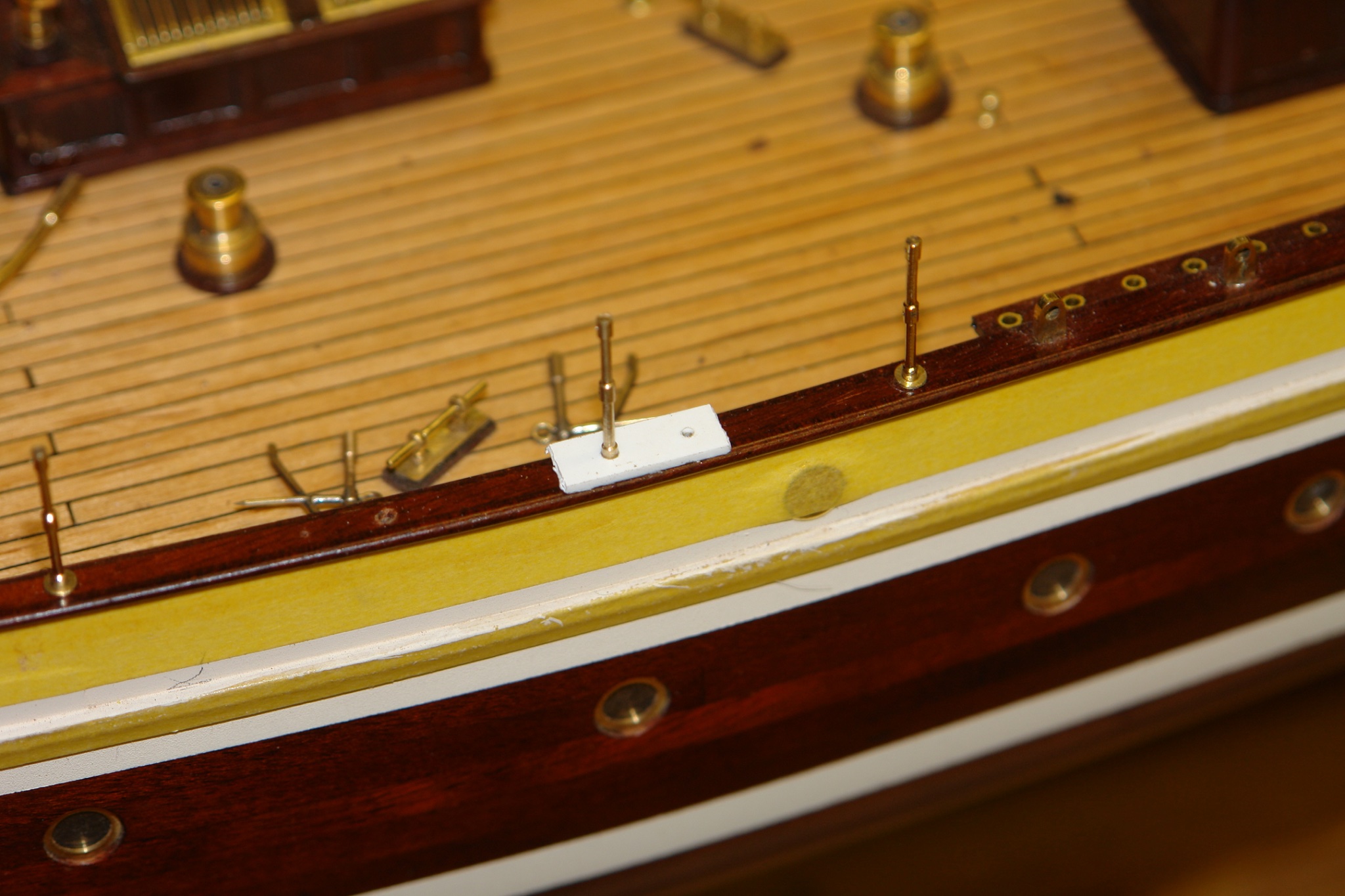
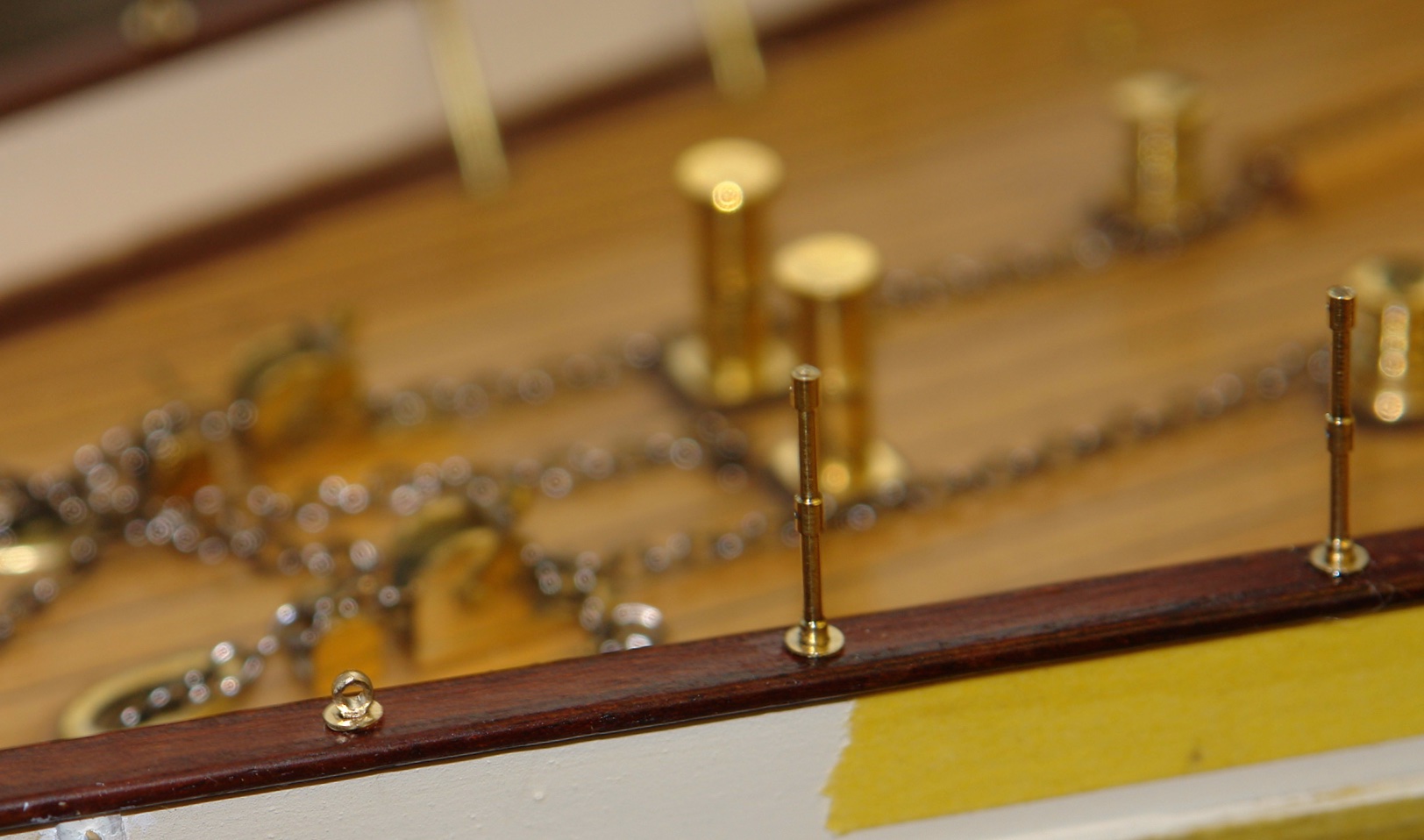
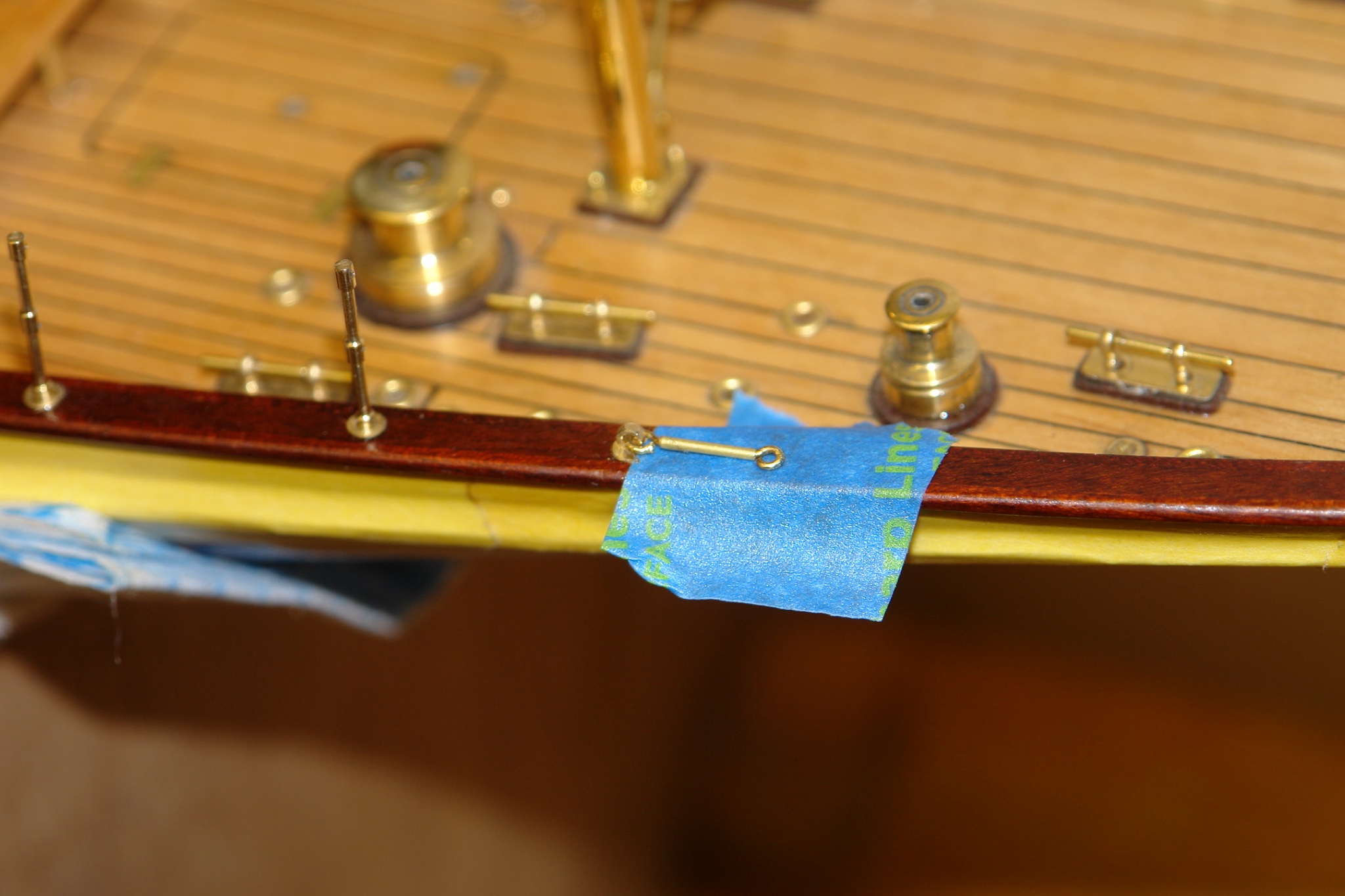
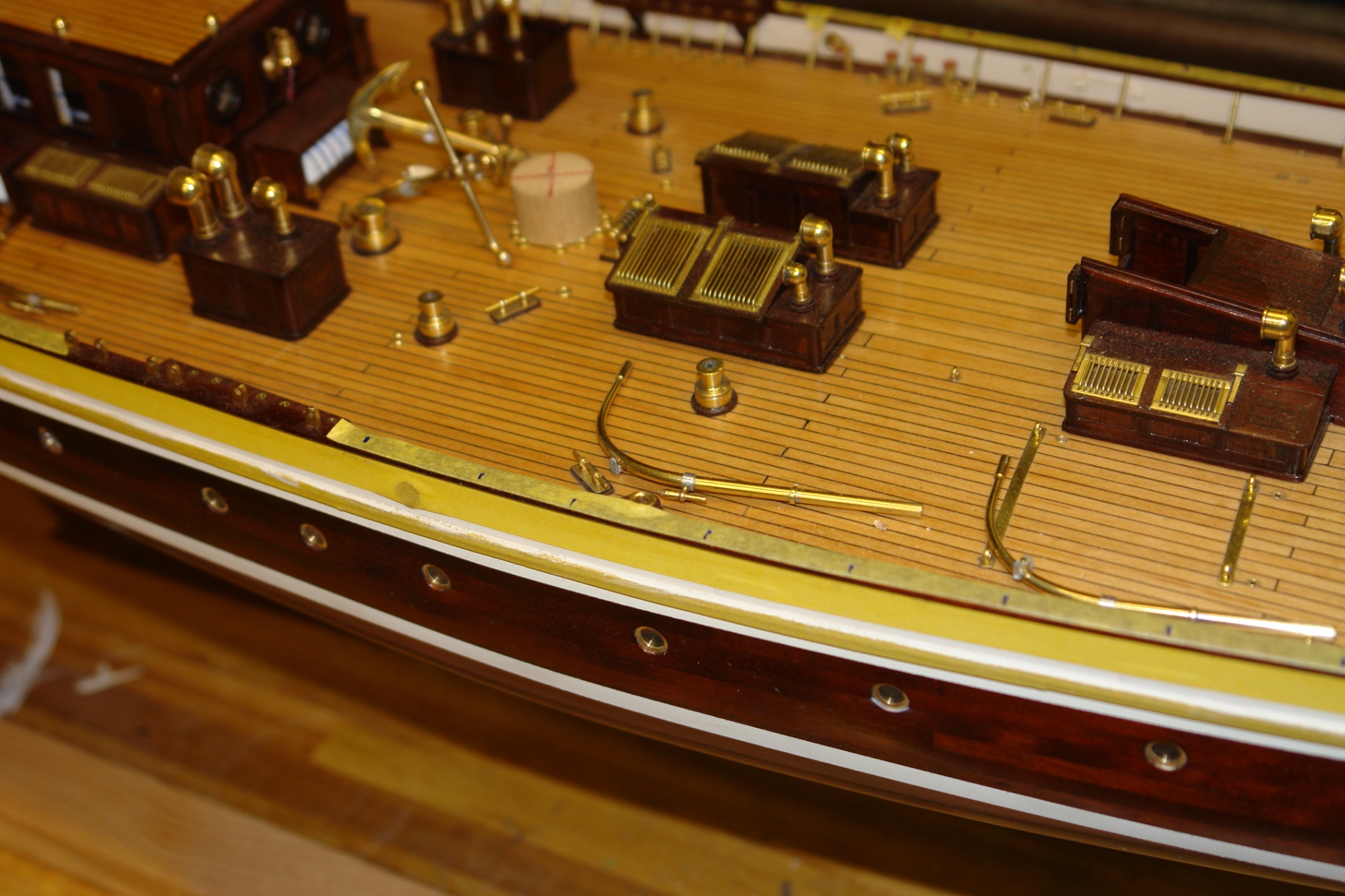
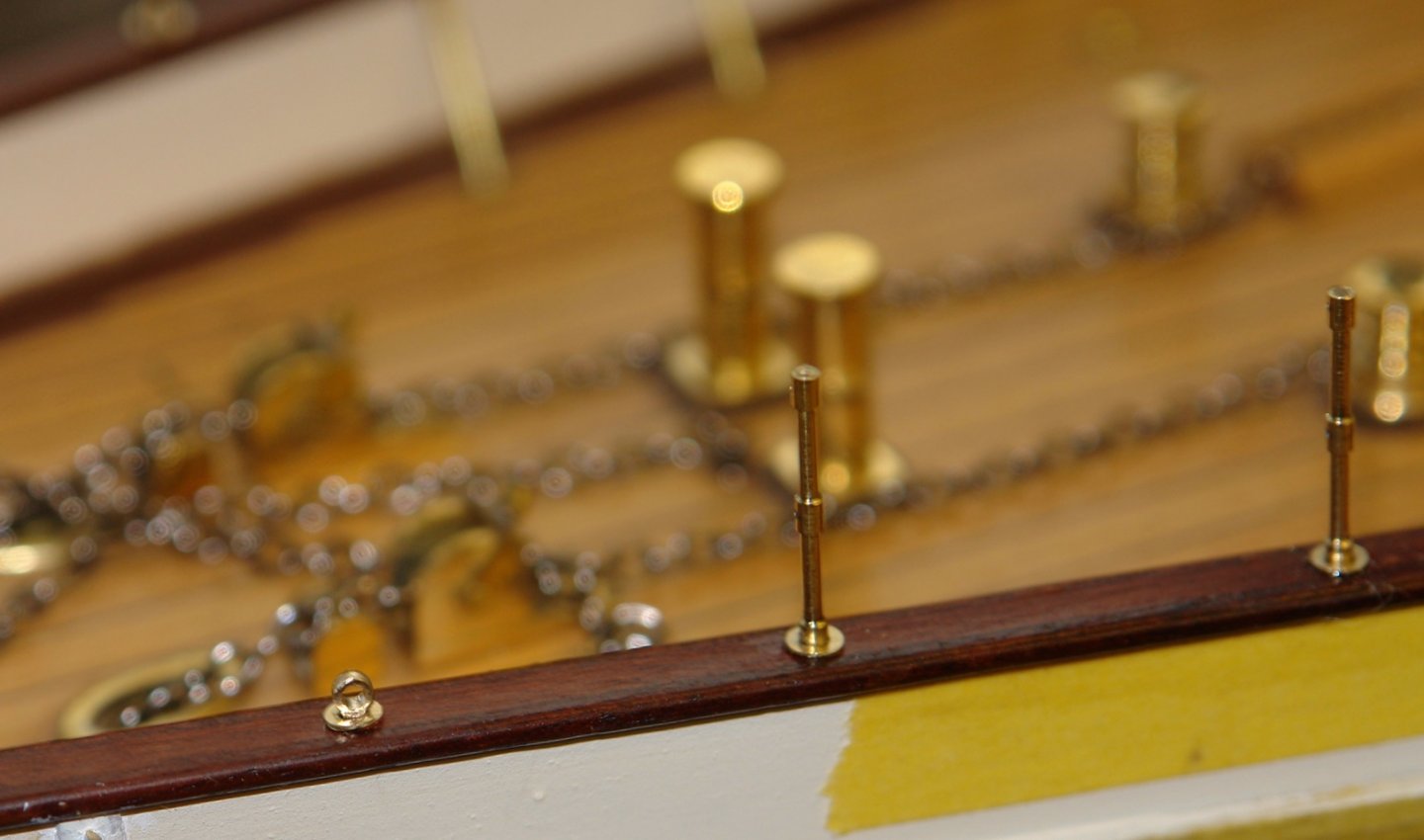
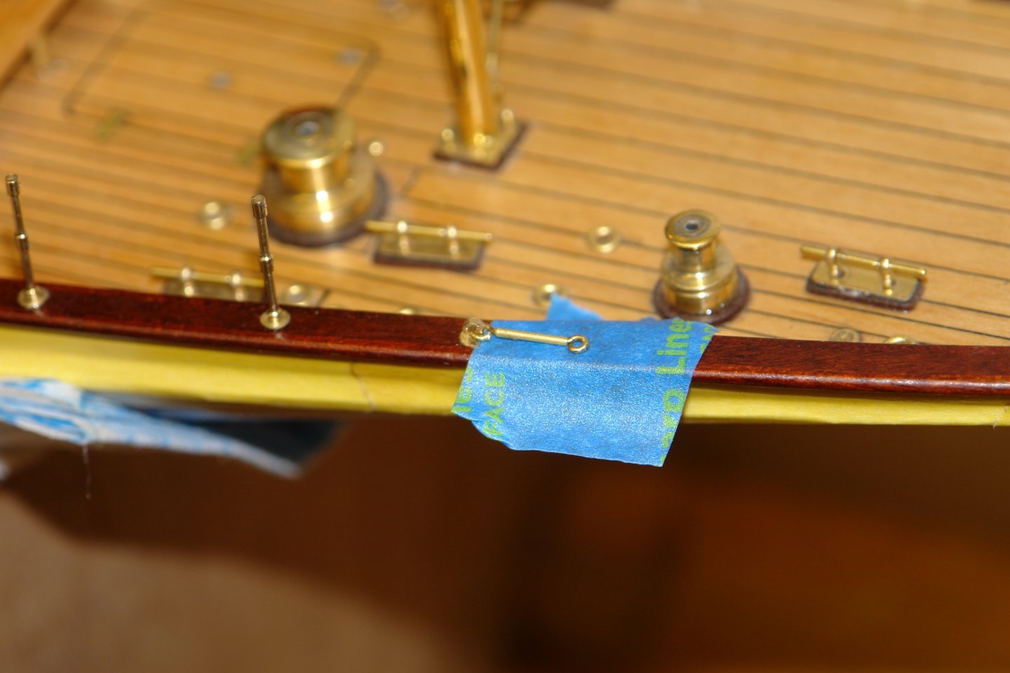
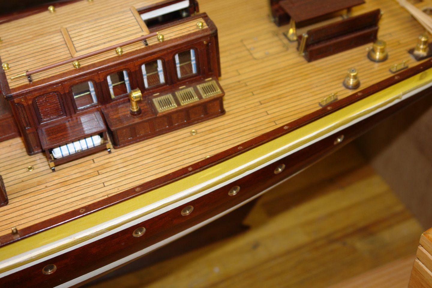
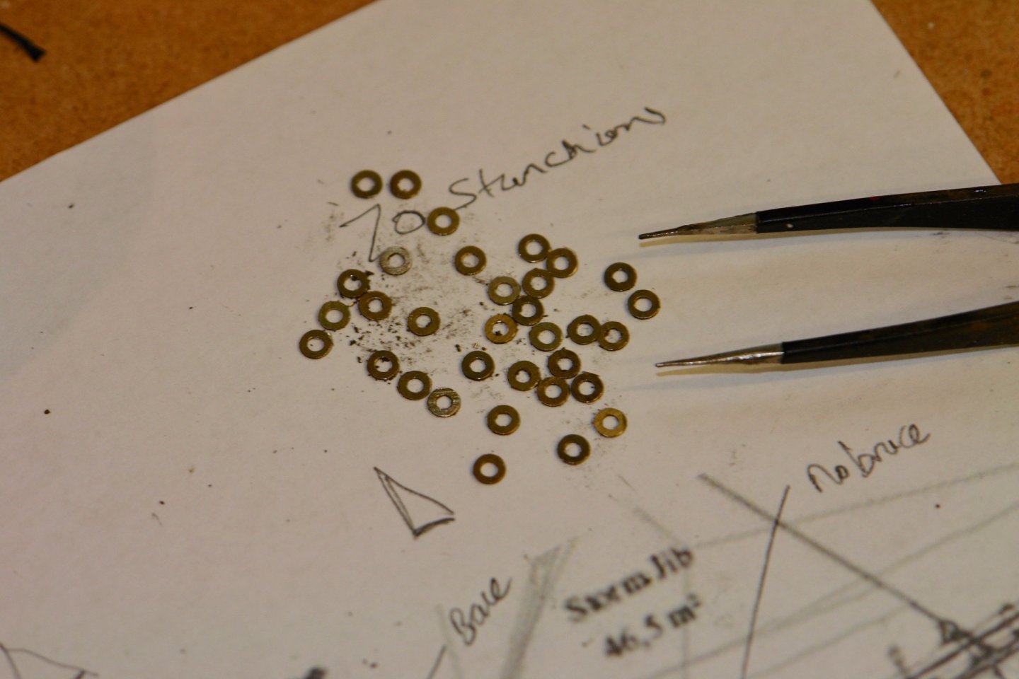
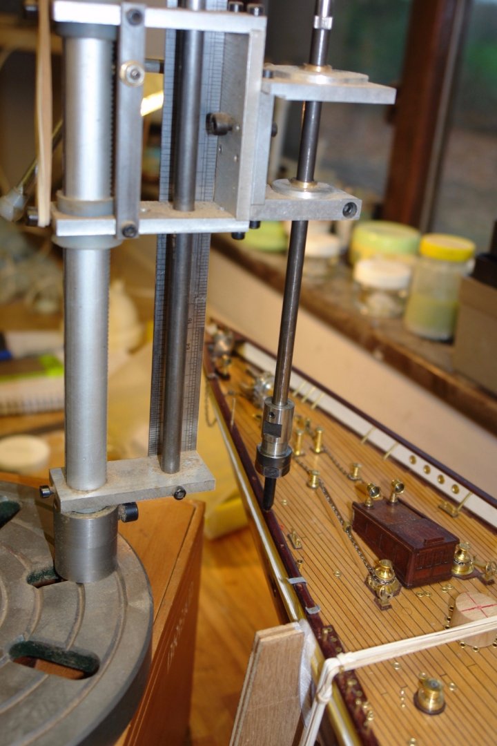
It has been a couple of weeks since I last posted a build update. The weather went from very cold to quite warm almost overnight prompting work on tiding the garden ready for spring. In consequence the shipbuilding suffered. I did manage to drill all the stanchions with either 2 or 3 x .025" holes depending on their purpose. A piece of a kitchen cutting board was used as a soft jaw to prevent damage. A couple of hundred holes later:- The stanchions fit into circular brass bosses on the rail. These bosses were made as brass washers from 1/8" rod. The rail needed to be drilled with .062" diameter holes to take the stanchions. The depth of drilling needed to be controlled to prevent the drill breaking through and damaging the hull. I made a stop for pressing over a 1/16" drill bit. The stanchion positions were marked out on masking tape attached to rails and then the positions were hand drilled using my home made drill press. The stanchions were a press fit in the rail so they were tapped home with a pin hammer. Once installed a .025" length of rod was passed through the stanchion top hole and the stanchion was rotated until the hole aligned with the rail. With the stanchions in place and correctly orientated a drop of CA glue was placed at the base and a washer was passed over to simulate the rail boss.


-
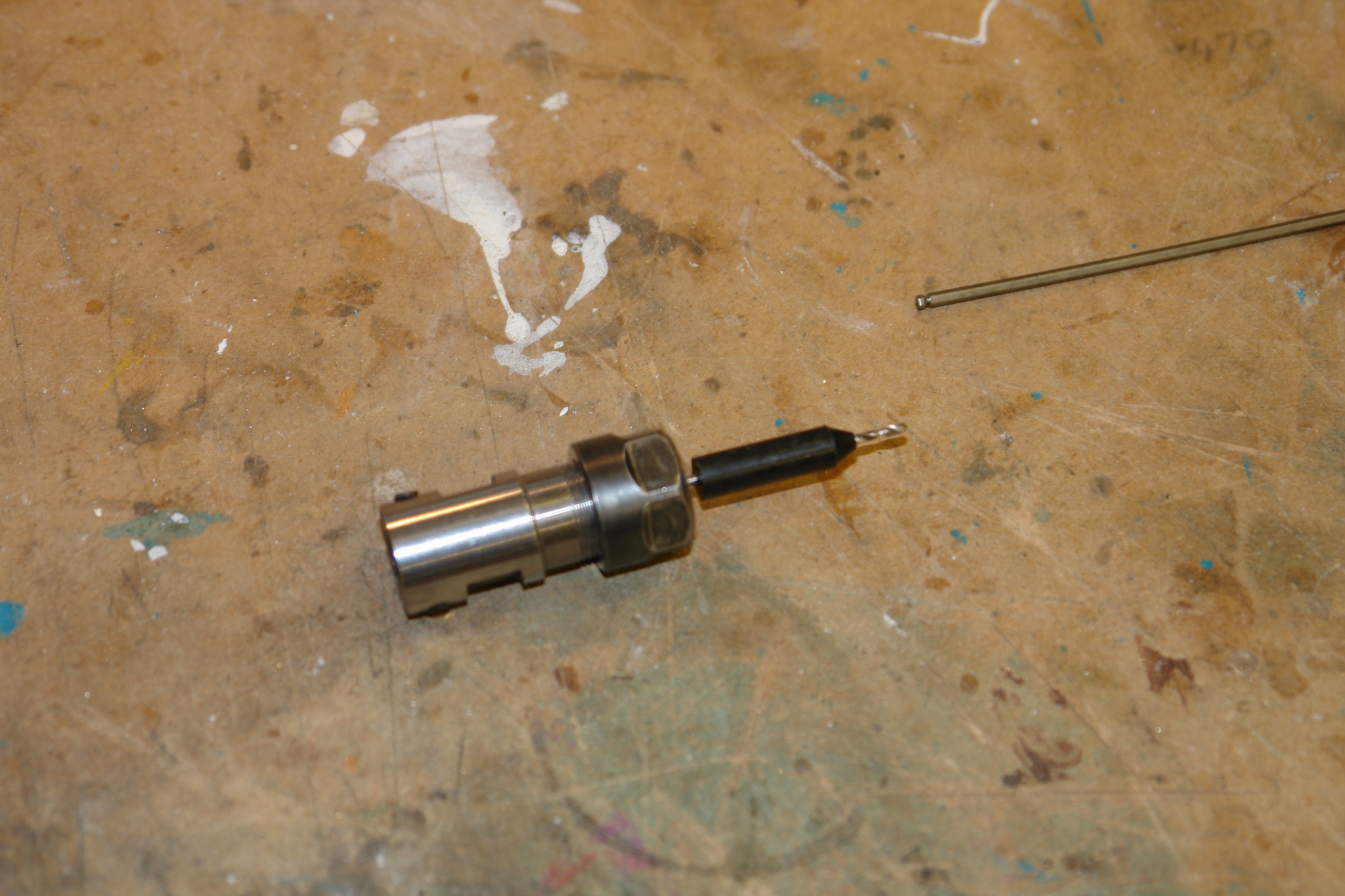
Interesting design of tailstock mounted steady Eberhard - i may have a go at making something which achieves the same effect. Nice detailed work as usual.
-
I admire your dedication Vaddoc, your description of the process is very engaging if not a little daunting.
-
You are either very brave or foolish.
-
Mark - I liked the "struggling to control the spinnaker" looks like broaching territory to me. I look forward to the next build instalment.