KeithAug
-
Posts
3,985 -
Joined
-
Last visited
Content Type
Profiles
Forums
Gallery
Events
Everything posted by KeithAug
-
 Eberhard, Keith, Michael, John, Richard, Steve, Vaddoc, Rob, Dale, Druey. Thank you all for taking an interest and commenting. Also thanks to everyone who has looked in. Ah, Pat you have caught me out taking short cuts. Thank you for commenting. Tom, it is just a bit of card. It is placed a few millimetres below the perspex of the window.
 -
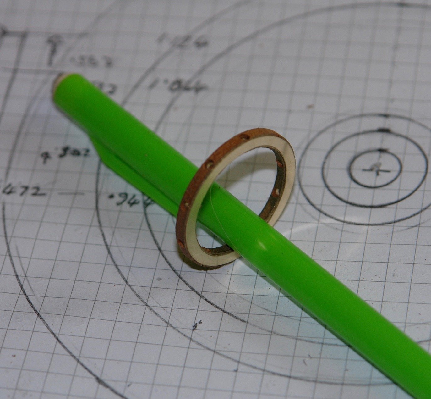
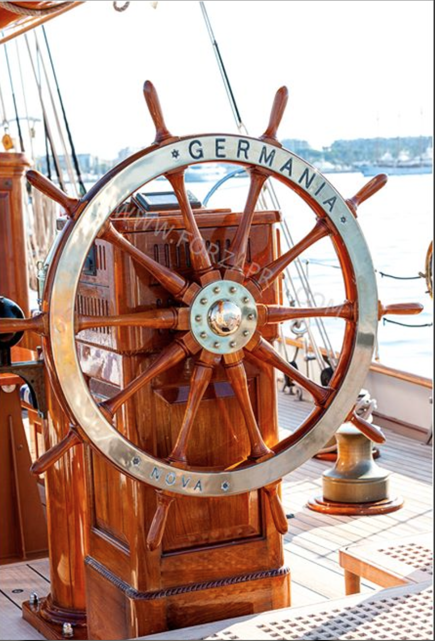
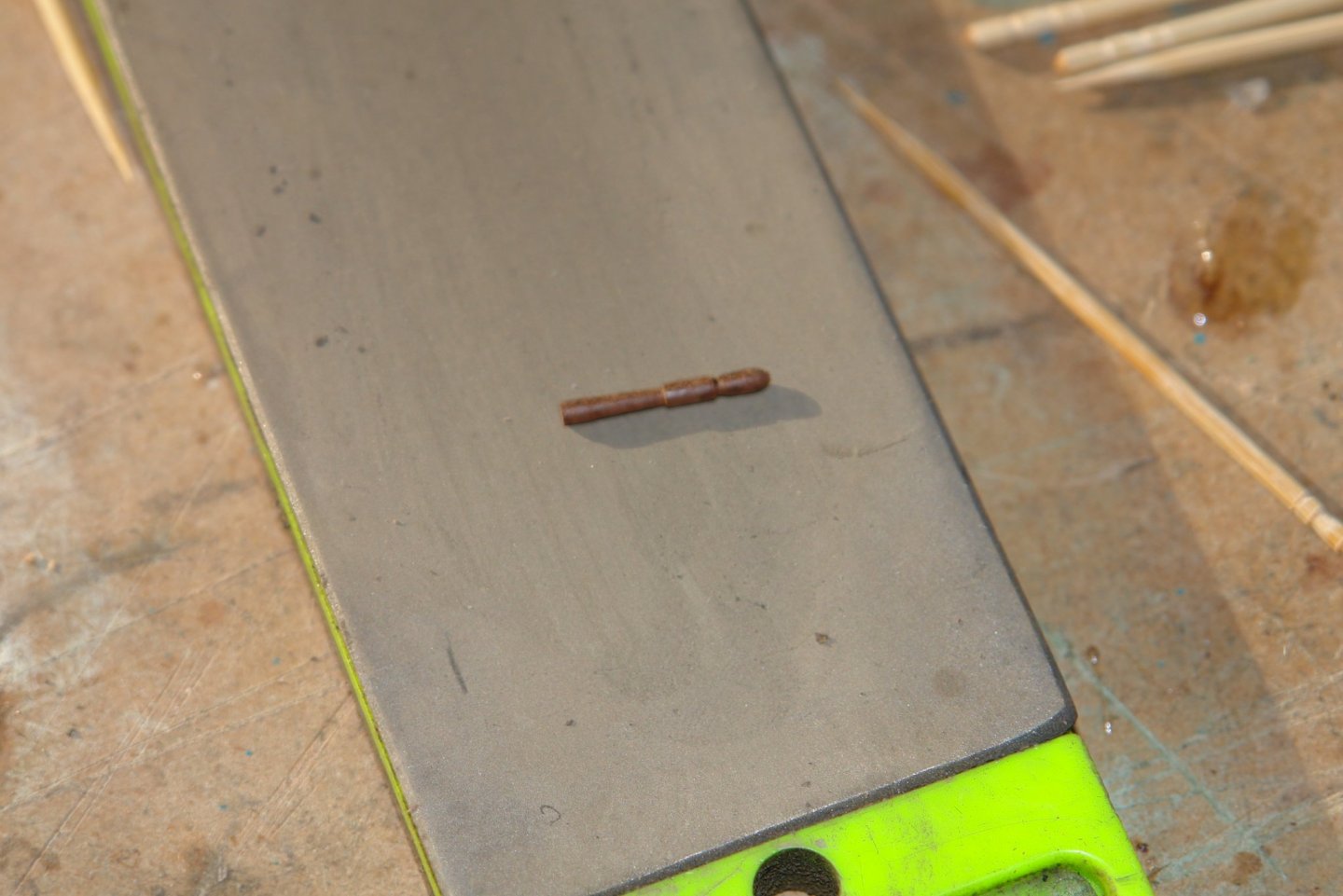
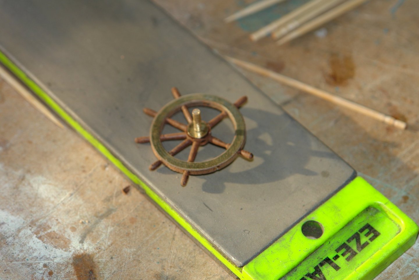
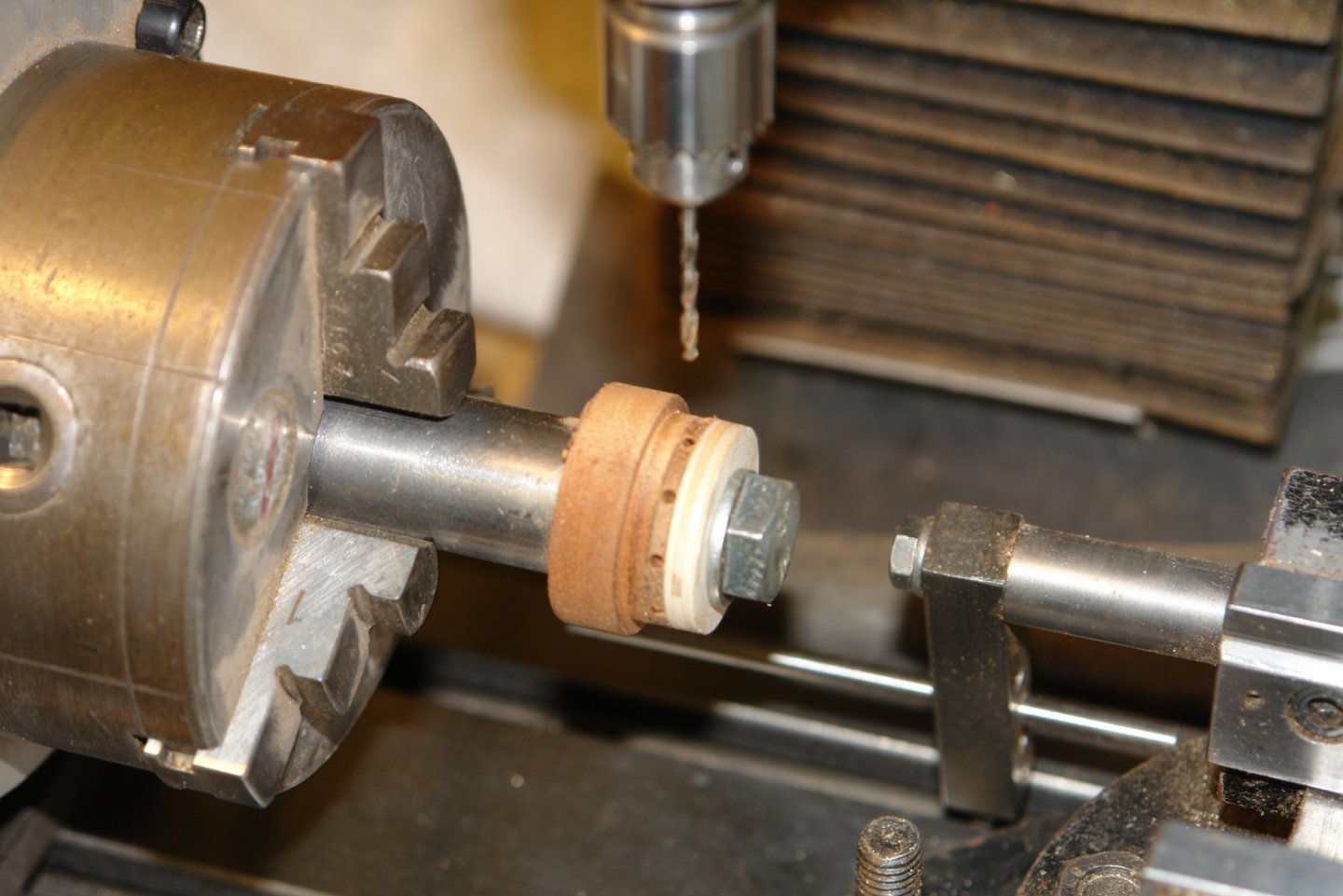
Thank you Steve, Chris and Michael, and thanks to everyone who has liked my build. I went on to finish the wheel. The brass faces and spindle for the hub were turned. I then turned a piece of mahogany and drilled the 10 radial holes to take the spokes. The drill is .080" diameter. It is quite difficult to tell that the grain on the rim does not follow the circumference. The hub was parted off and the spigot mounted. I made former from a brass tube to allow me to make the spindles. The spindles were installed and glued. I finished the wheel with a coat of poly. I then used the wrong end of a .020" drill to mark the positions of the rim screws. The wrong end was ground at an angle and the wheel was mounted on the mill rotary table to make the marks.

-
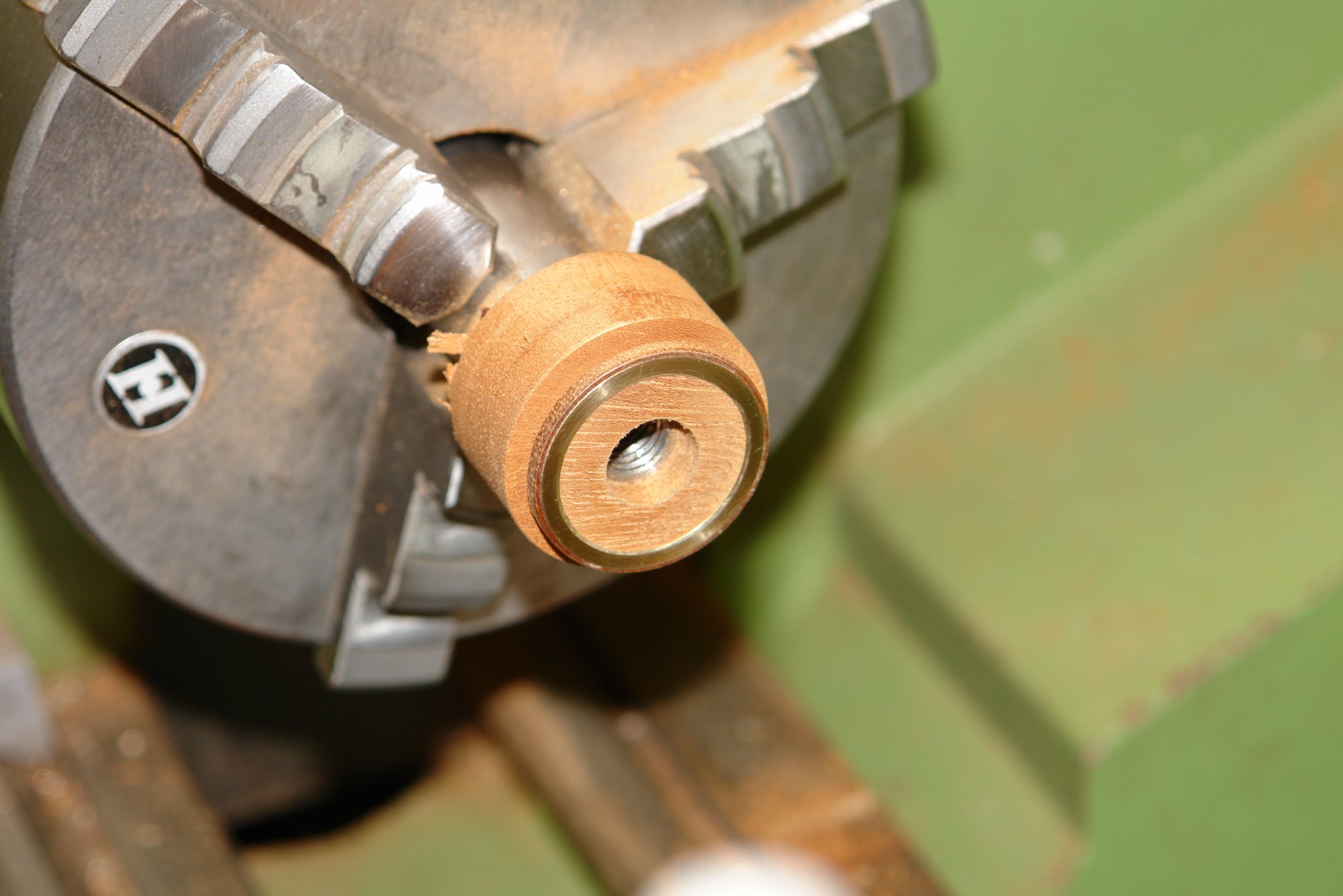
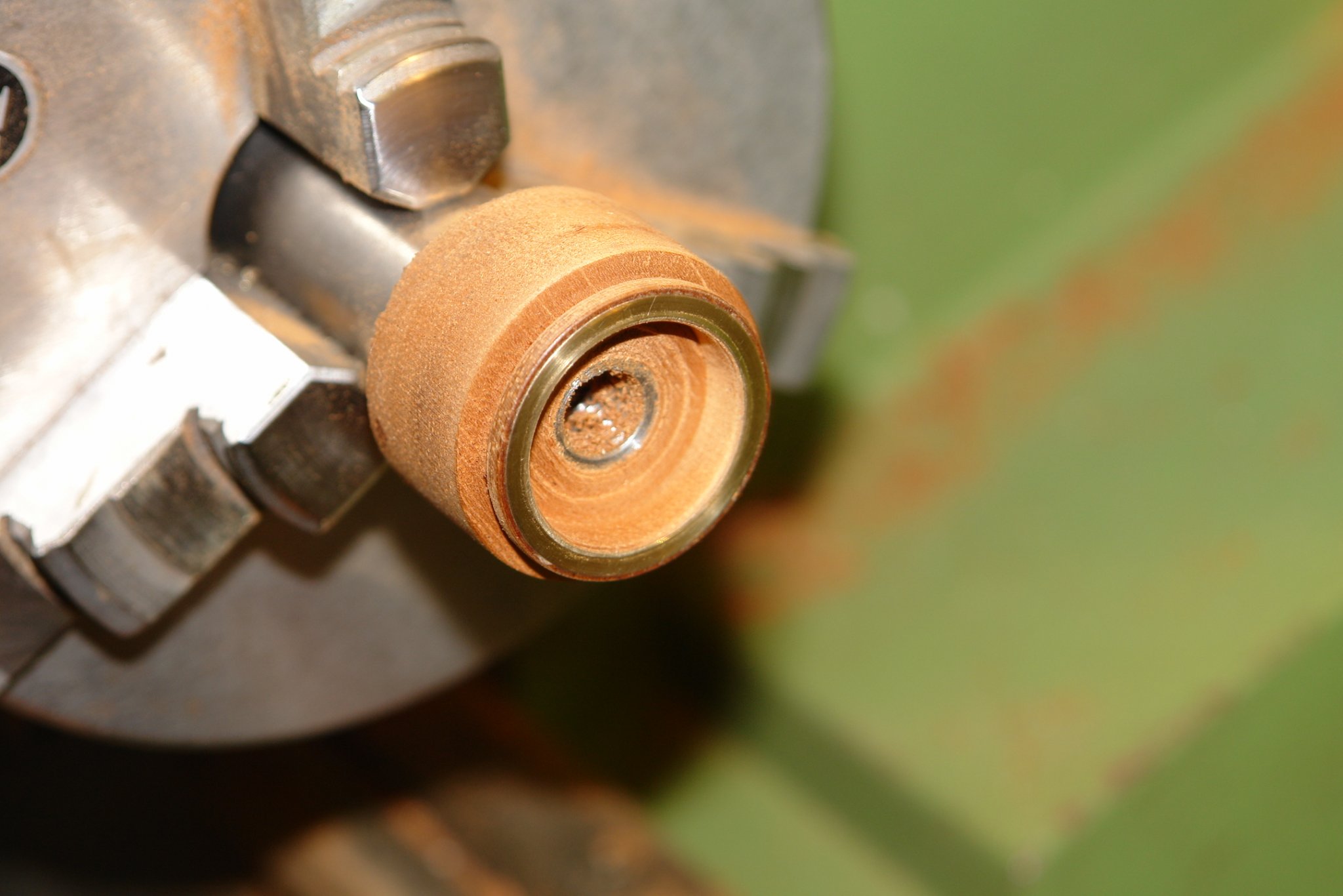
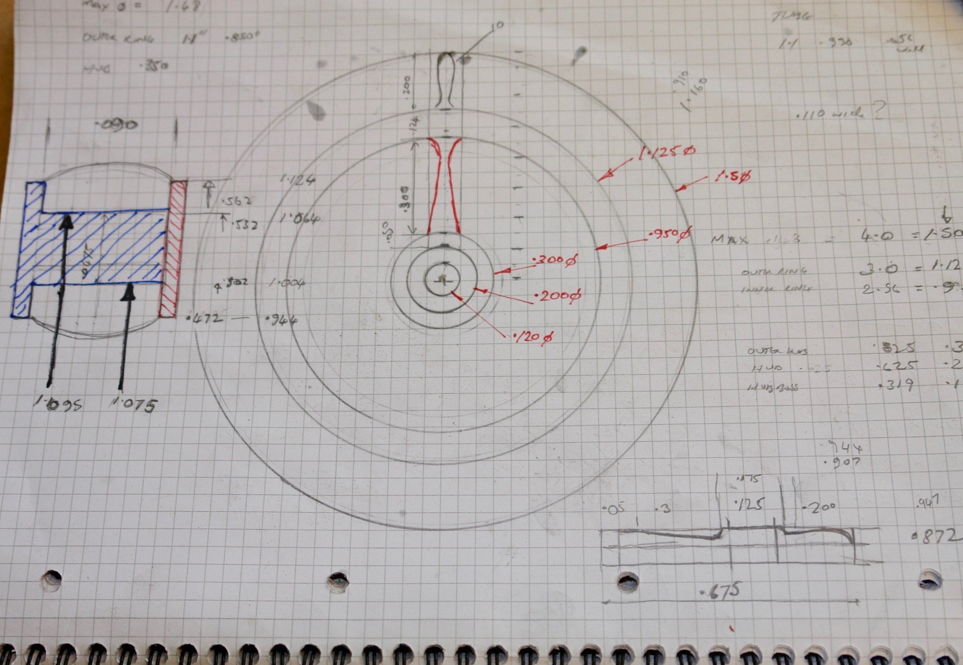
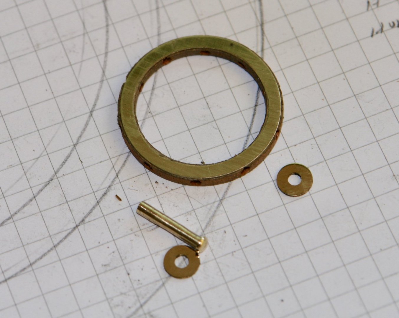
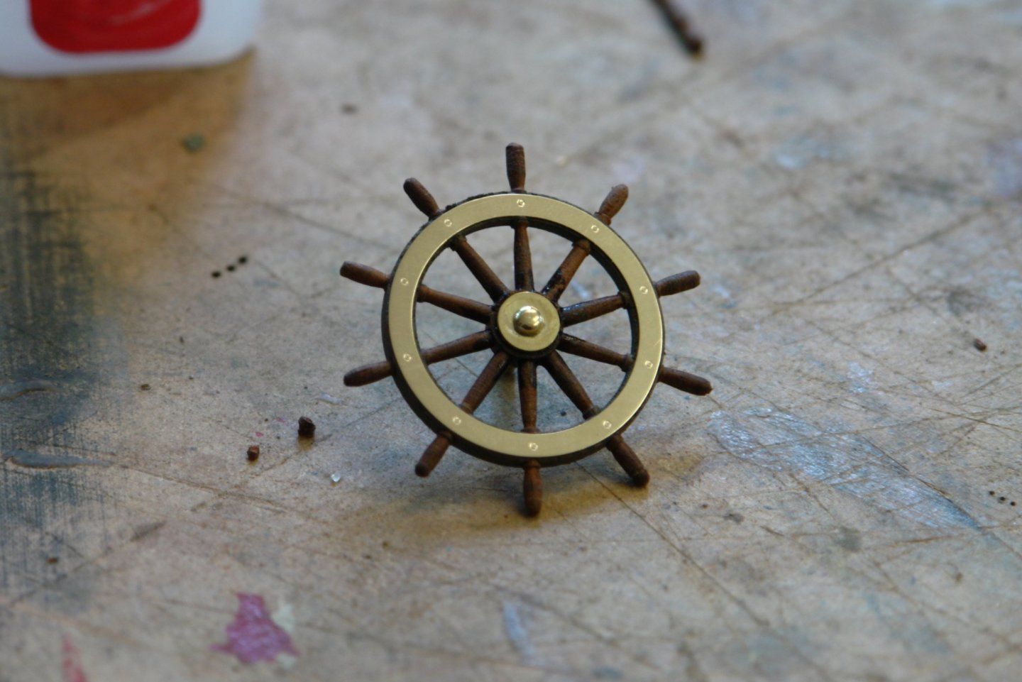
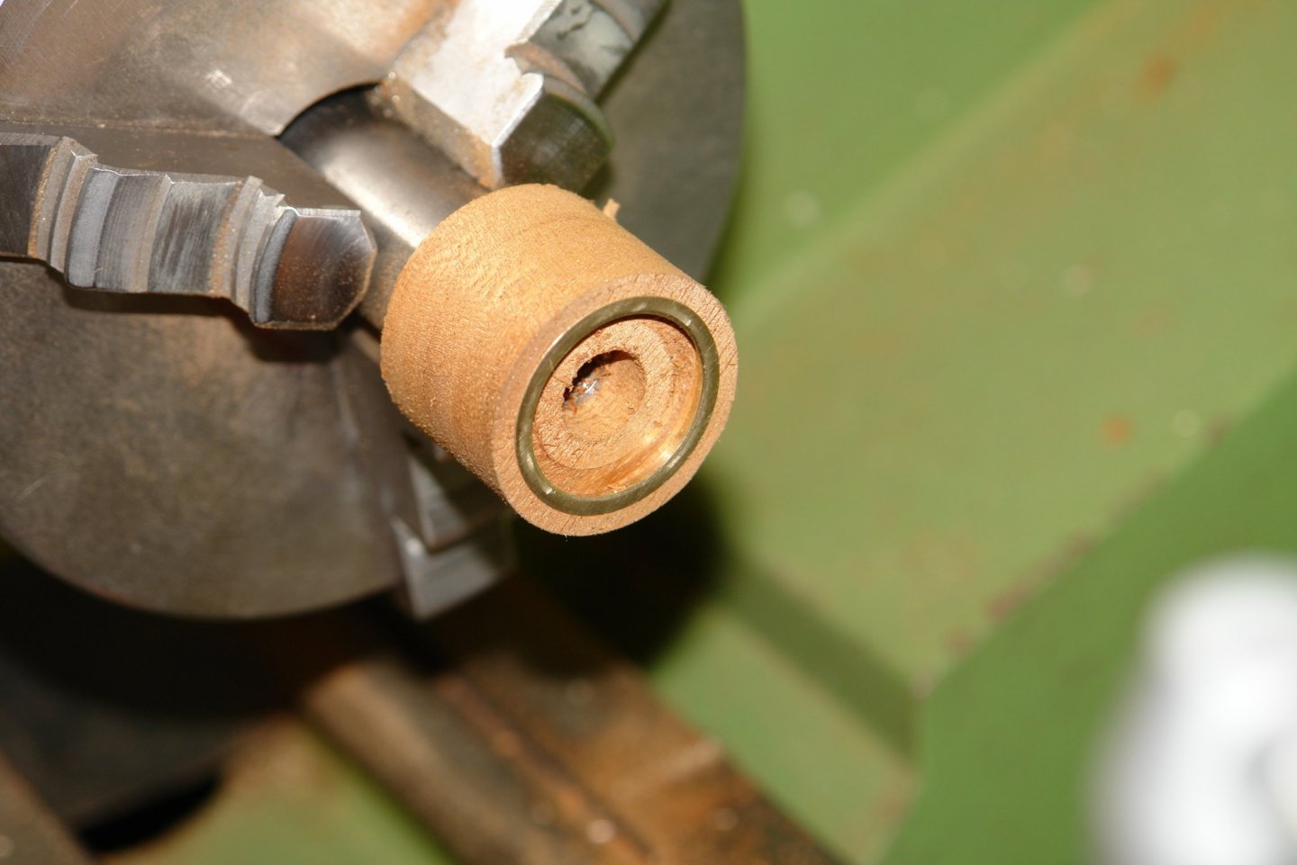
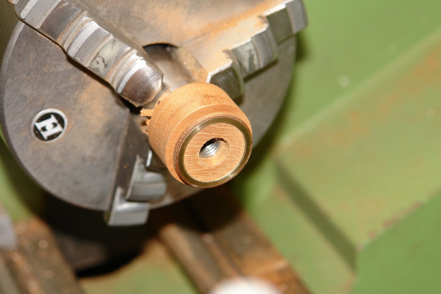
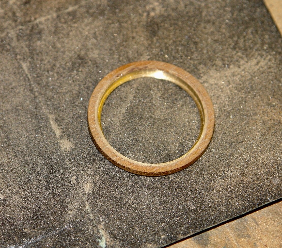
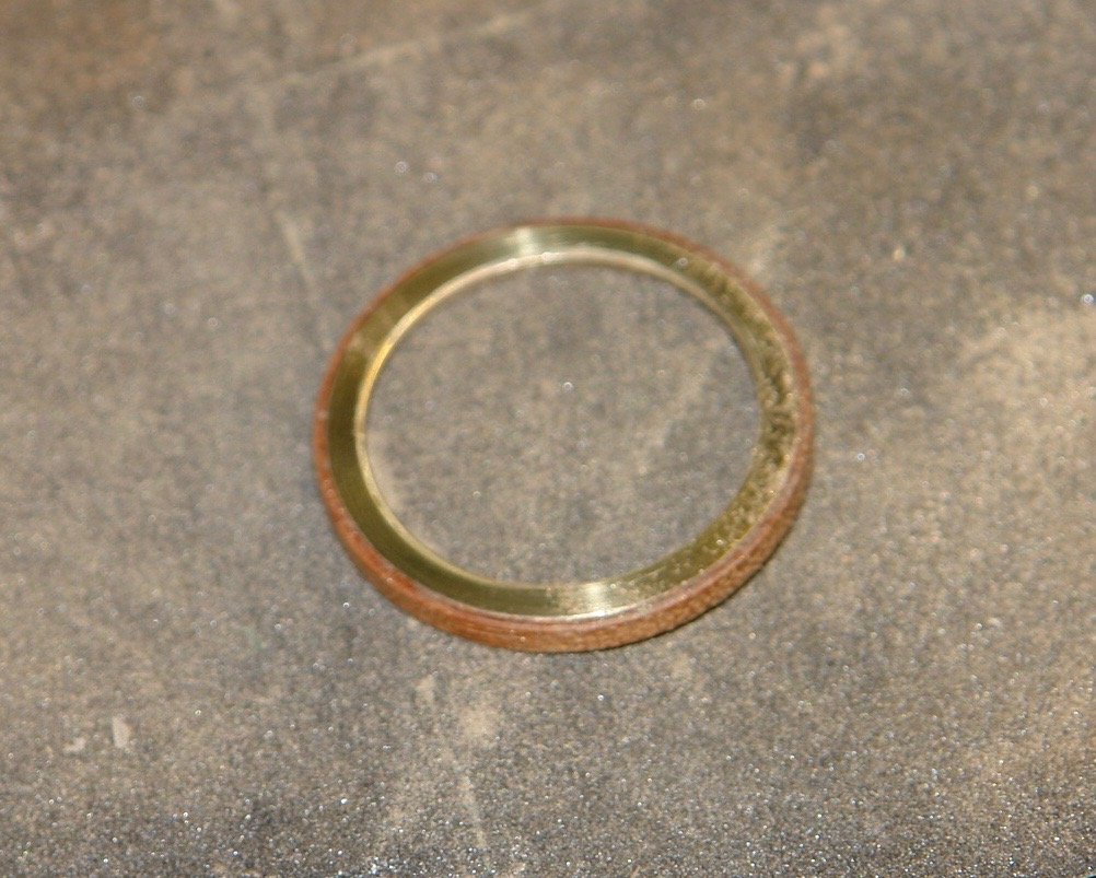
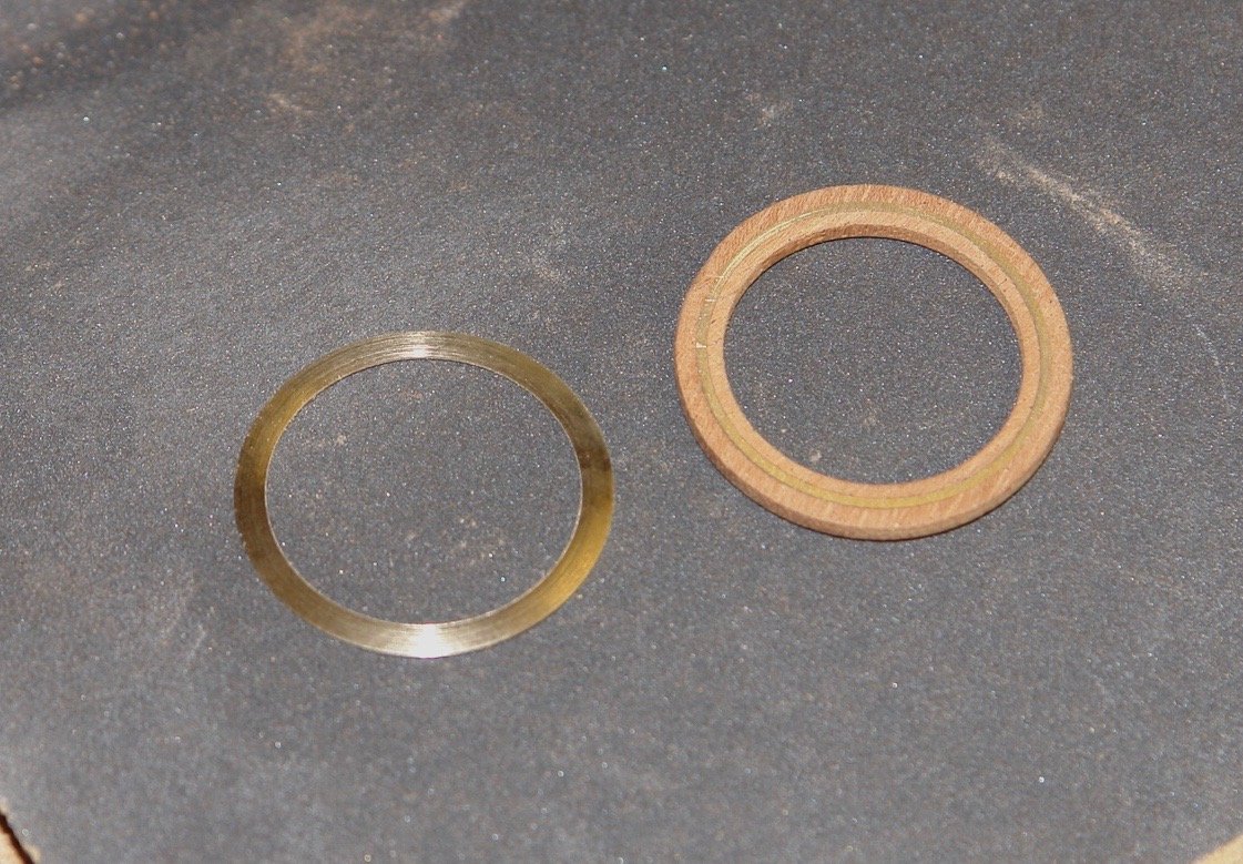
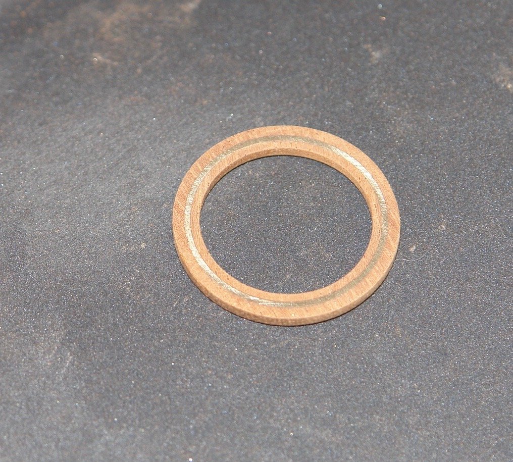
Thank you Michael - Good to see you back. I made a start on the wheel. I could scale the overall size from the plans and this coupled with a decent photograph allowed me to create a reasonable sketch. The rim is 1.125" OD and .950" ID. As can be seen the faces of there rim are predominantly brass mounted on a mahogany core. I am not sure why but I decided to make it in quite a complicated manner. I think strength was uppermost in my mind. On the left is a cross section of the rim. The blue and red areas areas represent the brass work. I started by finding brass of the right diameter, in this case an old plumbing fitting from the scrap box. I turned the Blue "T" shaped piece first and then parted off. I then mounted a lump of mahogany in the lathe and turned a bore to take the outside diameter of the "T" section (1.095" on the drawing). The brass was then glued in the bore with CA glue. The mahogany external diameter of the ring was then turned and rim was parted off. A spigot was then turned on the mahogany to mach the inside diameter of the "T" section (1.075" on the drawing). The parted off rim was then glued onto this spigot. The inside was then bored out to the required .950" diameter of the inside of the rim. I then parted off the rim which now consisted of the brass "T" section with inner and outer mahogany hoops. I then turned a hoop of brass for the opposite face and glued it on with CA. I then mounted the hoop on yet another spigot and drilled the 10 radial holes to take the spokes of the wheel. That took all day.


-
Jon ----- We are still subject to the 2 meter rule - no sailing on this side of the pond unless its single handed. Ship coming along well, nice rigging drawing in earlier post - very clearly illustrated.
-
No Keith, It's been quite hot here so hopefully Paul has just taken to the garden or has been cat walking.
-
Vaddoc - Thank you for your comments and the tip - i will have a look. Hubert - thank you.
-
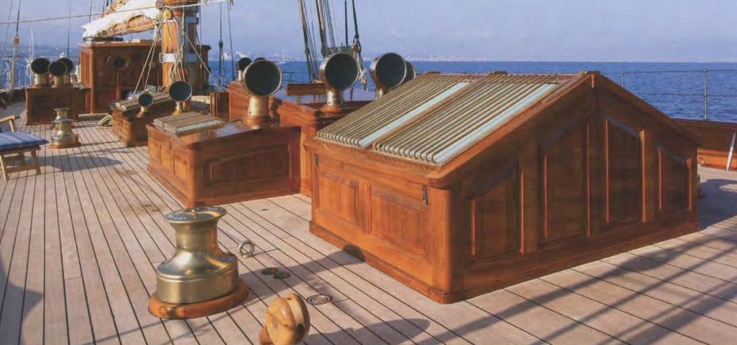
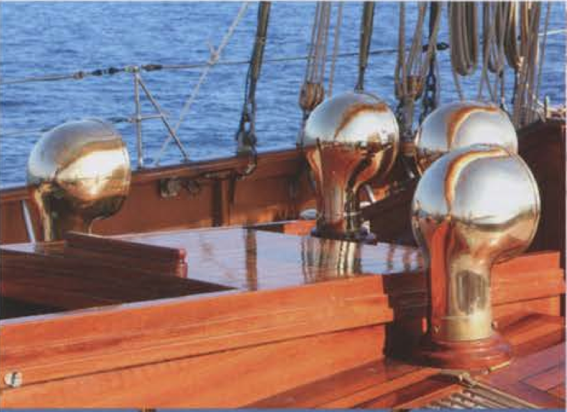
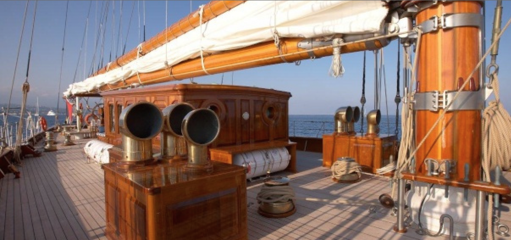
Roger - it has a full aircon system but it is built as a replica of the 1908 version, I think the cowls are more to do with historical accuracy than they are to do with function.
-
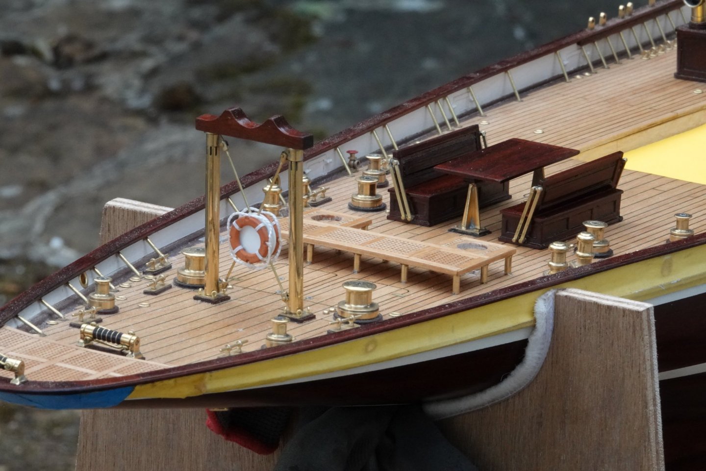
Dave, thank you for your appreciation - the vents on the original can be rotated - they tend to be facing forward when at anchor (to capture the wind). When sailing they generally point aft (to avoid capturing the spray). I am going to build the model with the sails up - so I pointed then rearward. At anchor:- Sailing:-

-
Keith - Amazing what can be done with simple hand tools. But I think I'll stick with my lathe thank you.
-
Richard, Druxey, Zbip, Thank you. I attach below the final sequence of photos and then I will get back to documenting the build. Sorry about the dust in some photos, I must remember to dust before shooting next time.


-
Exceptionally fine work Richard and beautiful detail.
-
Its always good to have an eye for detail, I just marvelled at the level of detail, I must try harder. The roller track looking very authentic. It seems the arc of fire was limited to forward of abeam - or am i just misreading the drawing?
-
Ekis, Moab, Noel, Kris - Thank you all for your appreciative comments. Eberhard. I used my better camera with a large zoom and small aperture and plenty of light (outside in the early afternoon with partial cloud). It was just quicker to do it that way but I do intend to try photo stacking. I agree a lot of brass to keep clean - and I am fairly sure it is not gold plated. Moab, Noel, - Thank you Keith - you are right I have not made the wheel yet. It is however near the top of my list. I just have to remember where I put the list. Bob - thank you for such a detailed explanation - very informative and educational. Druxey. Its a bit of both. The crutch isn't glued in and the starboard leg isn't quite all the way home. That said the actual lean is almost imperceptible and most of it is down to camera angle and lens distortion.
-
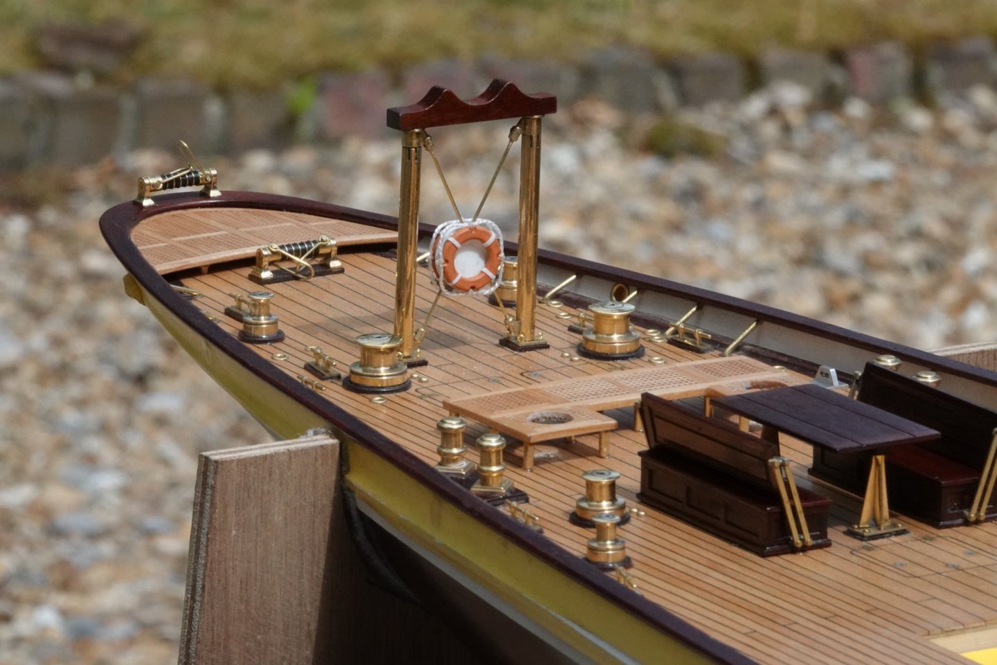
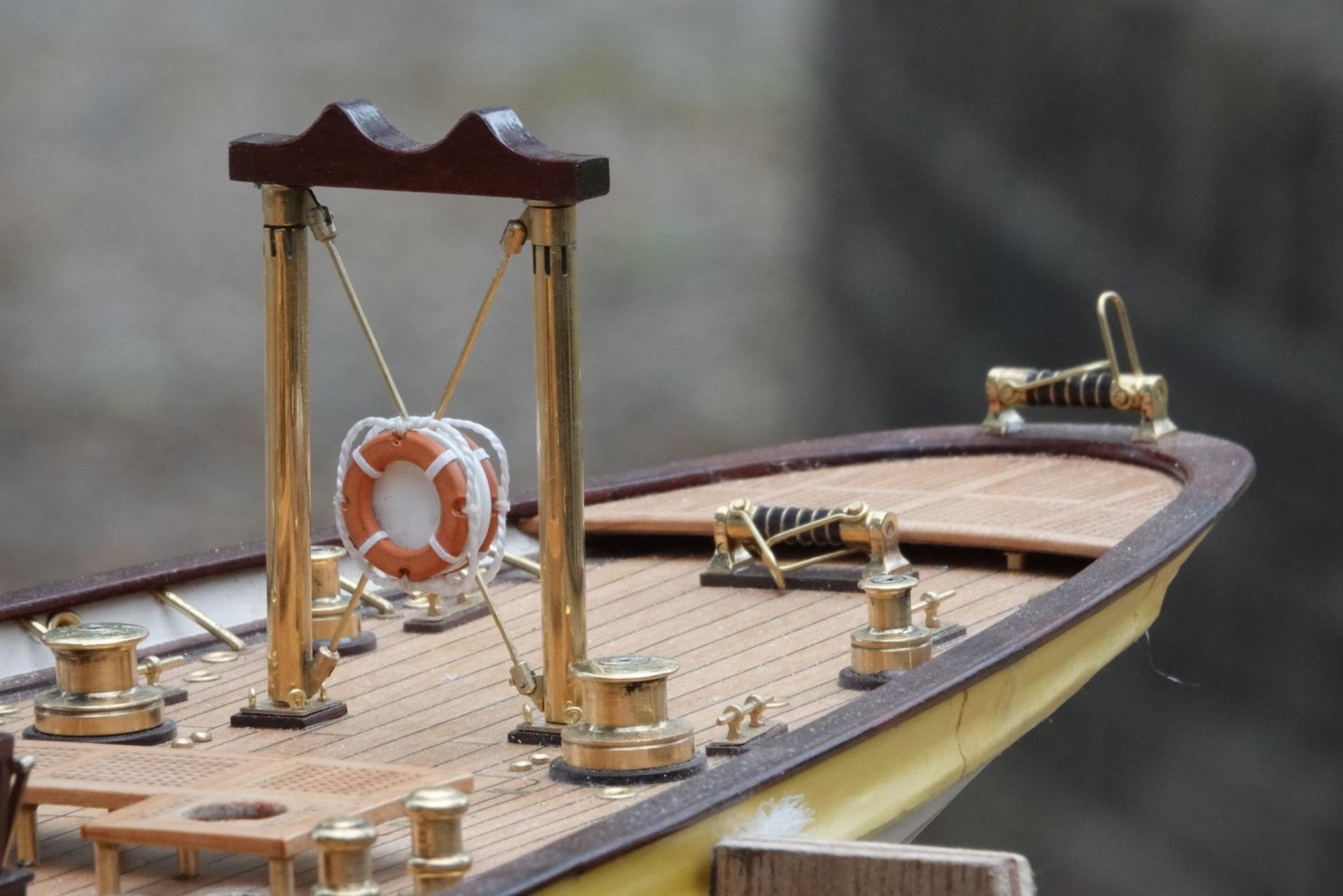
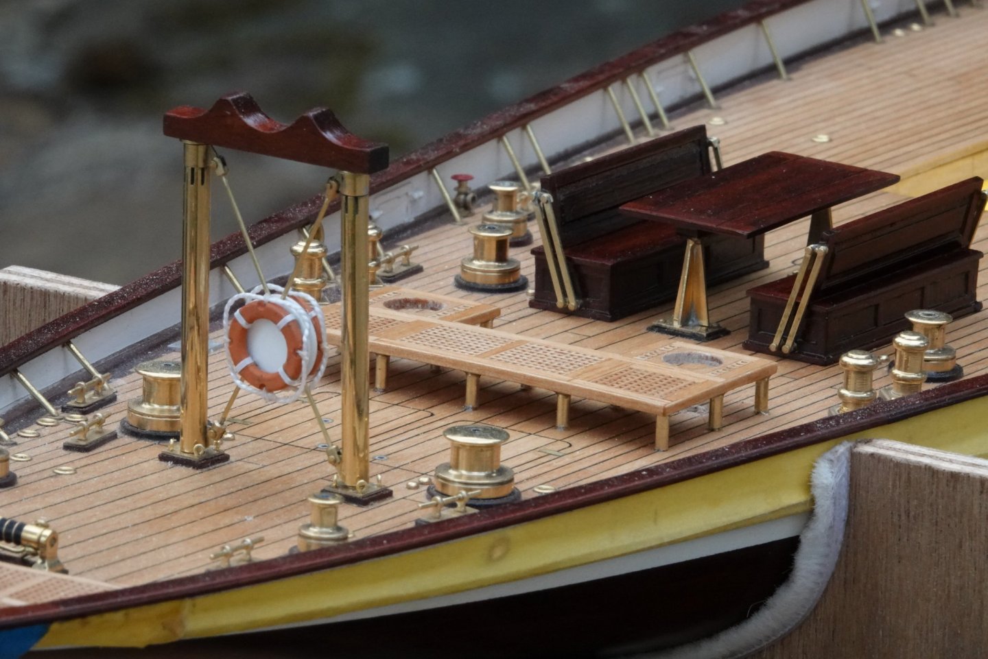
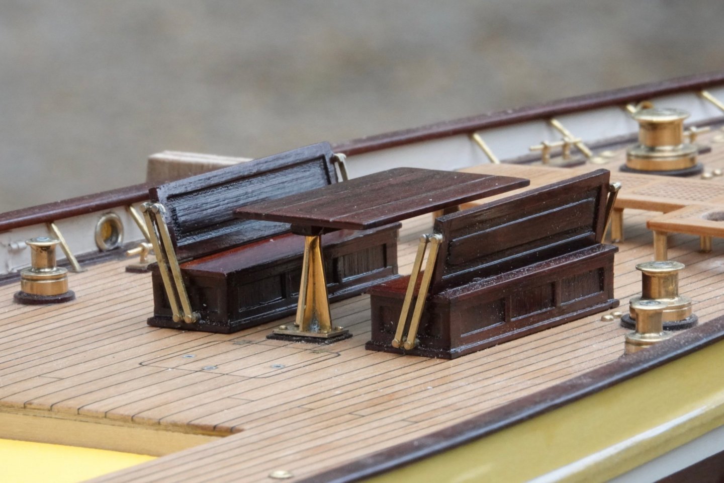
Keith, John, Pat, Mark - thank you and as ever thank you to everyone for the likes. A few more pictures:-


-
Looks like a fascinating build. I think I’ll tag along.
- 158 replies
-
- 1
-

-
- byblos ship
- Egyptian
- (and 1 more)
-
George, Thank you for there compliment. The metal I use is brass - an alloy of copper and zinc, bronze is an alloy of copper and tin. Brass does tarnish over time (even indoors) losing its sheen and becoming quite dull, this takes several years. If you want it to remain bright you can paint it with lacquer. I quite like to see the brass age so I don't bother but I am in the minority in this respect. Roger - thank you.
-
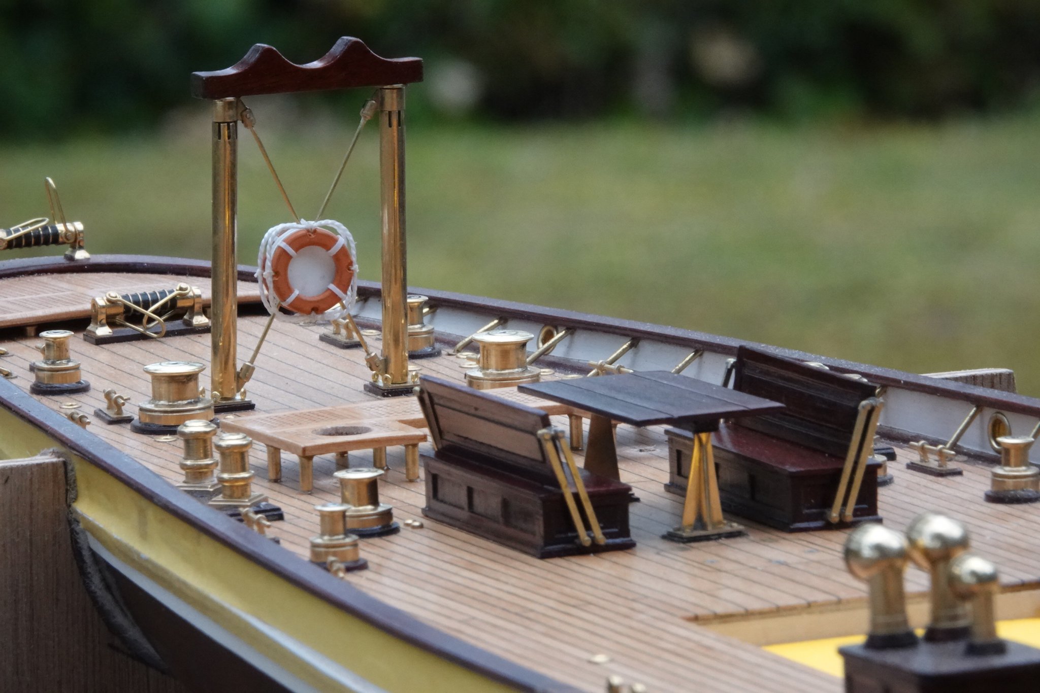
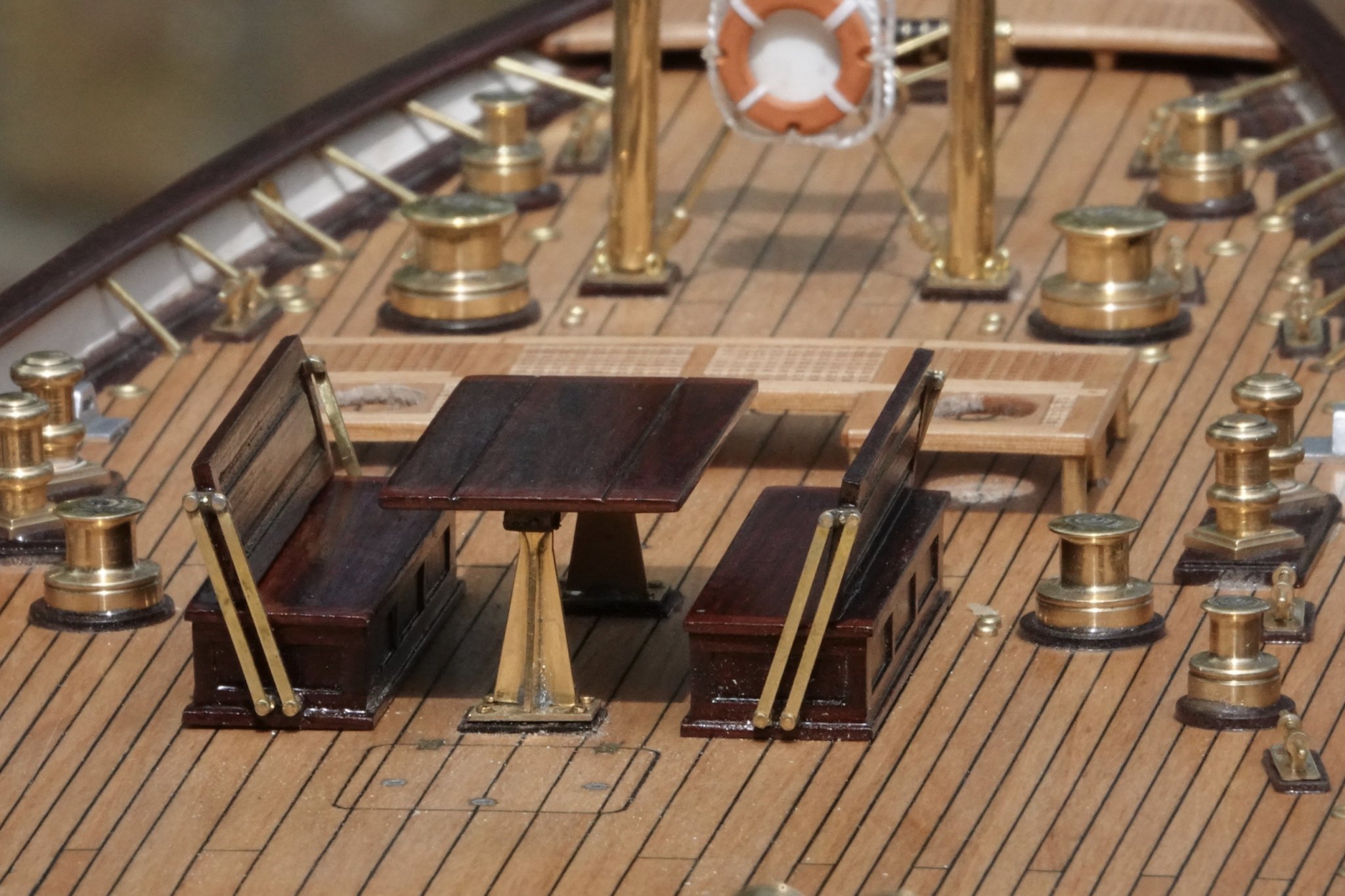
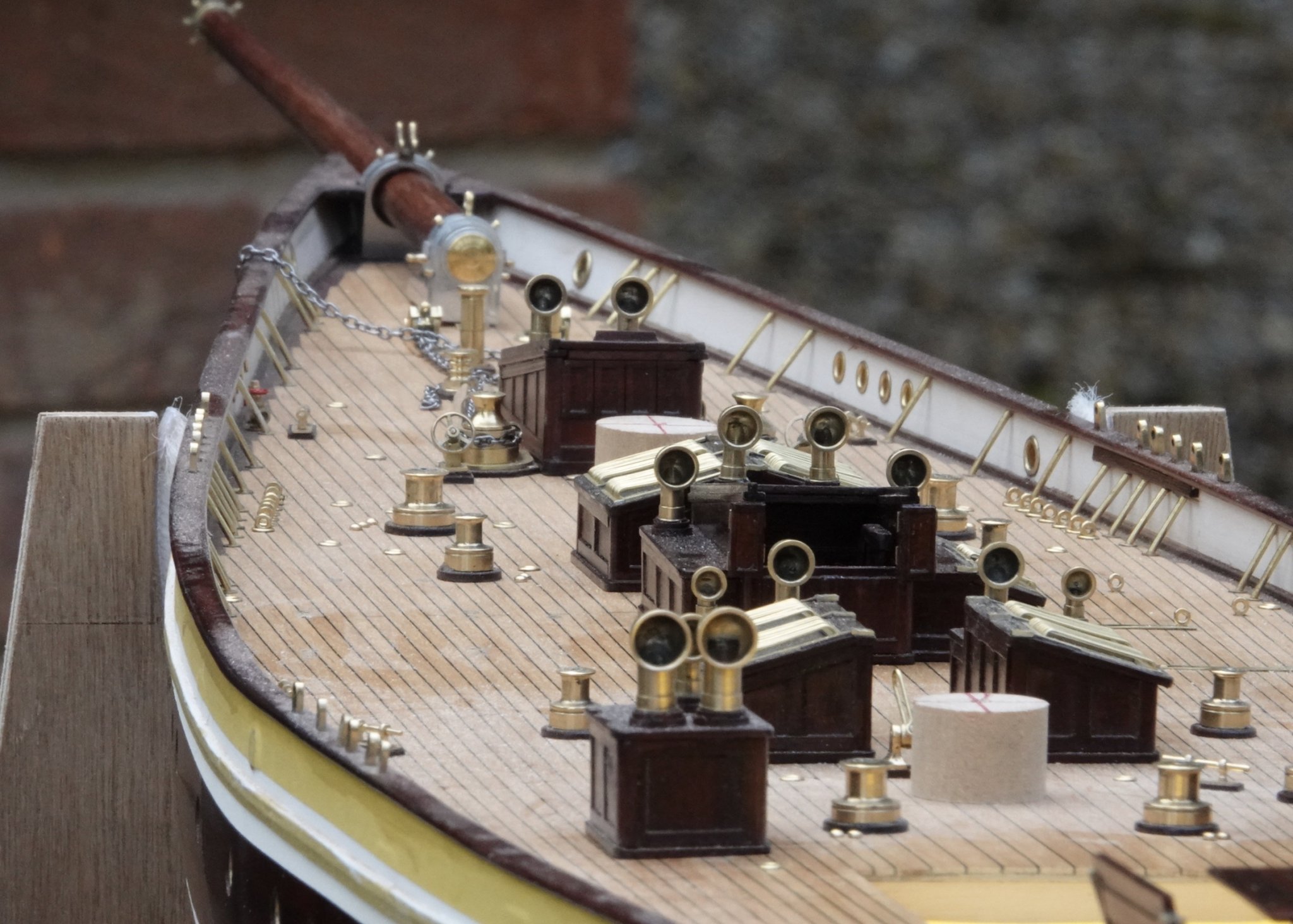
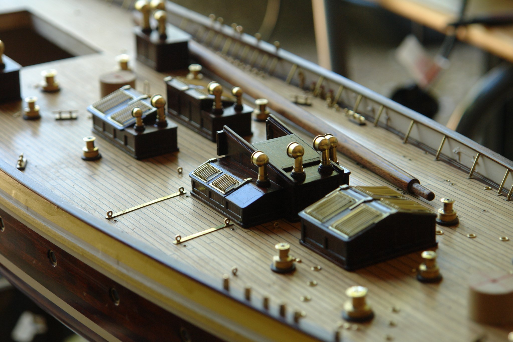
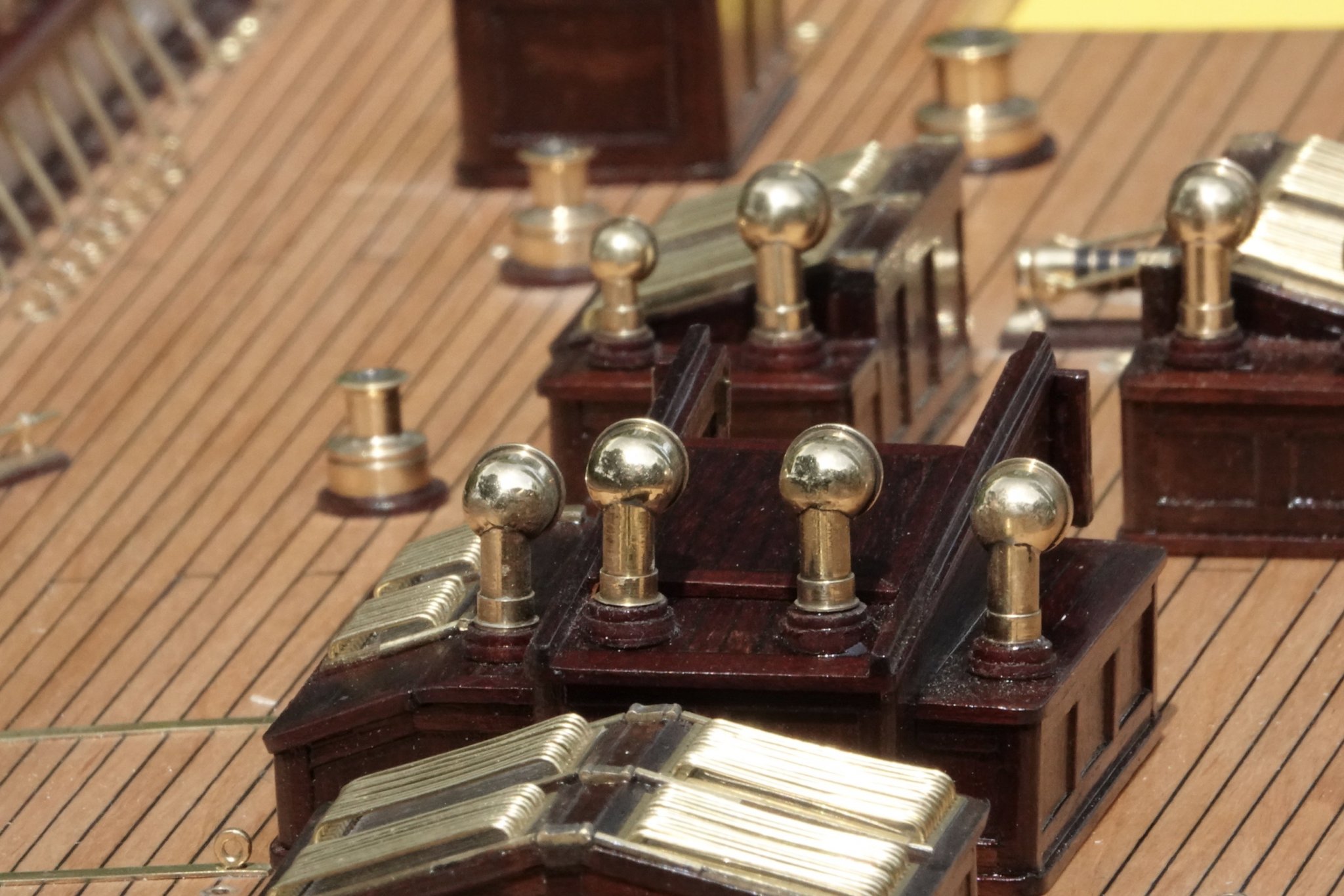
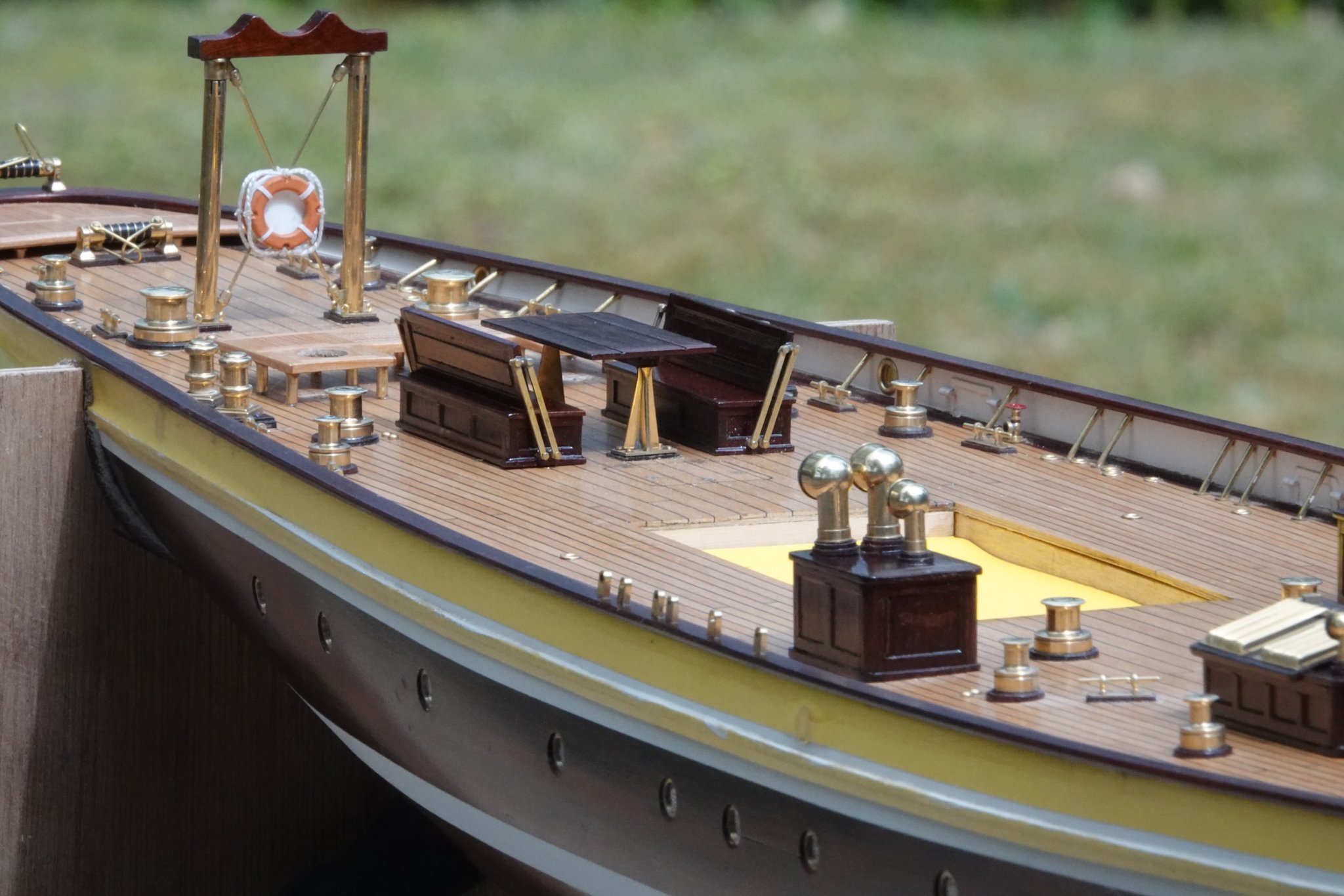
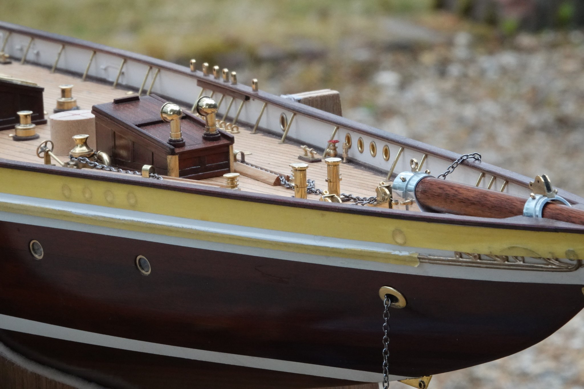
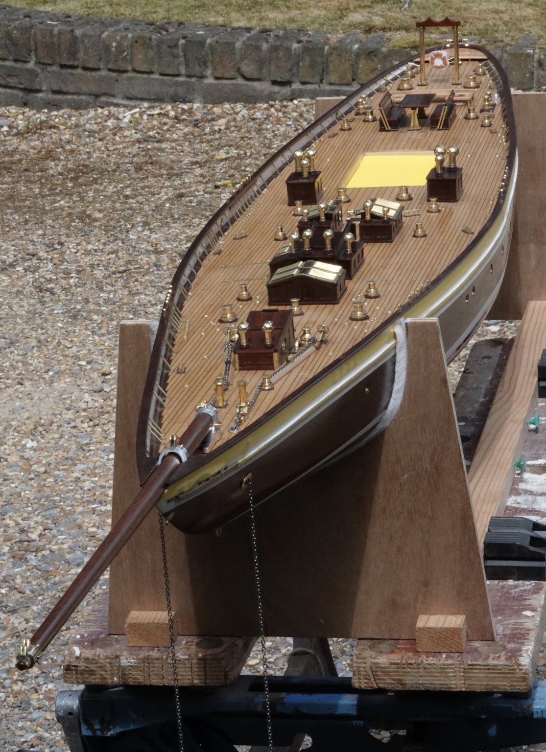
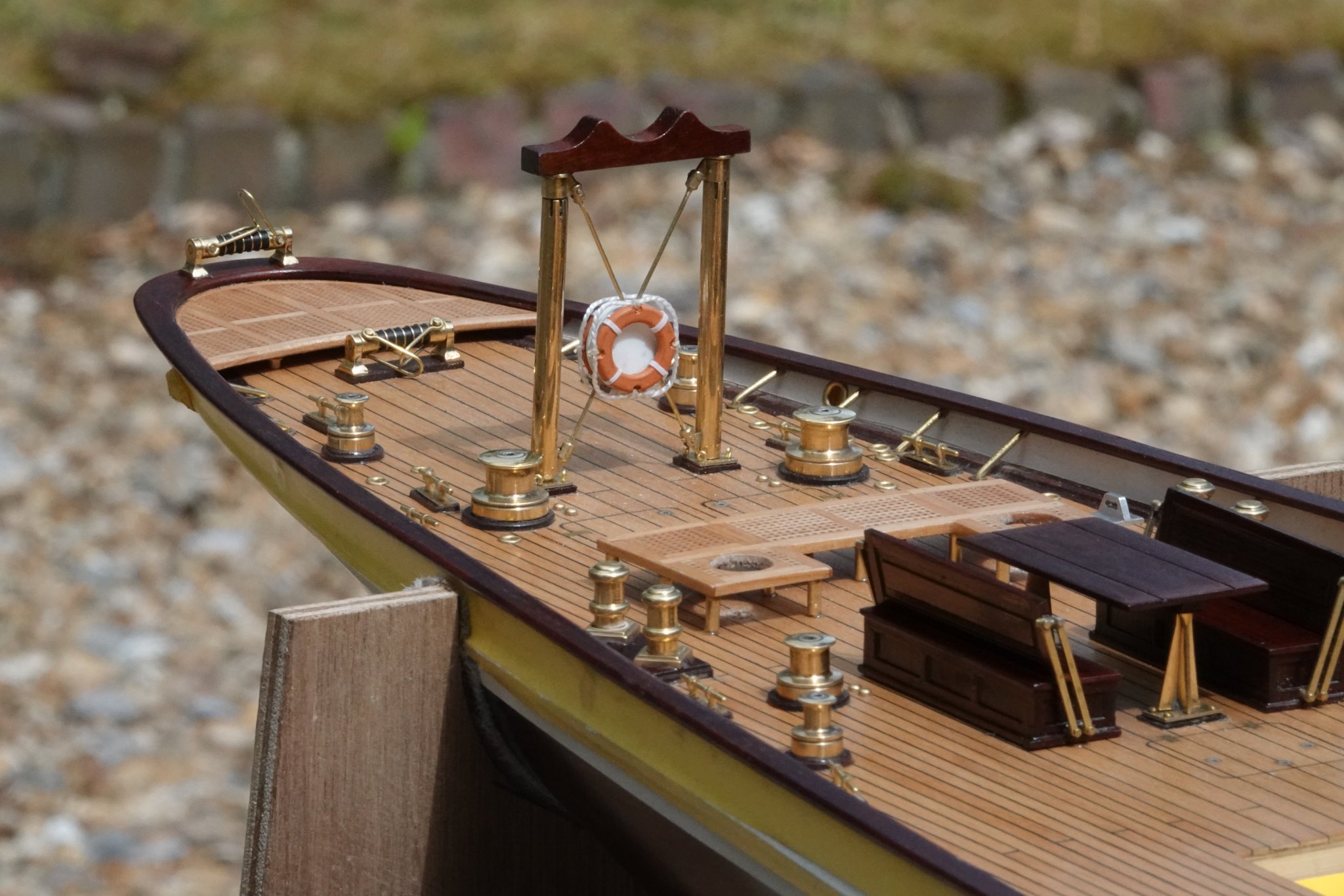
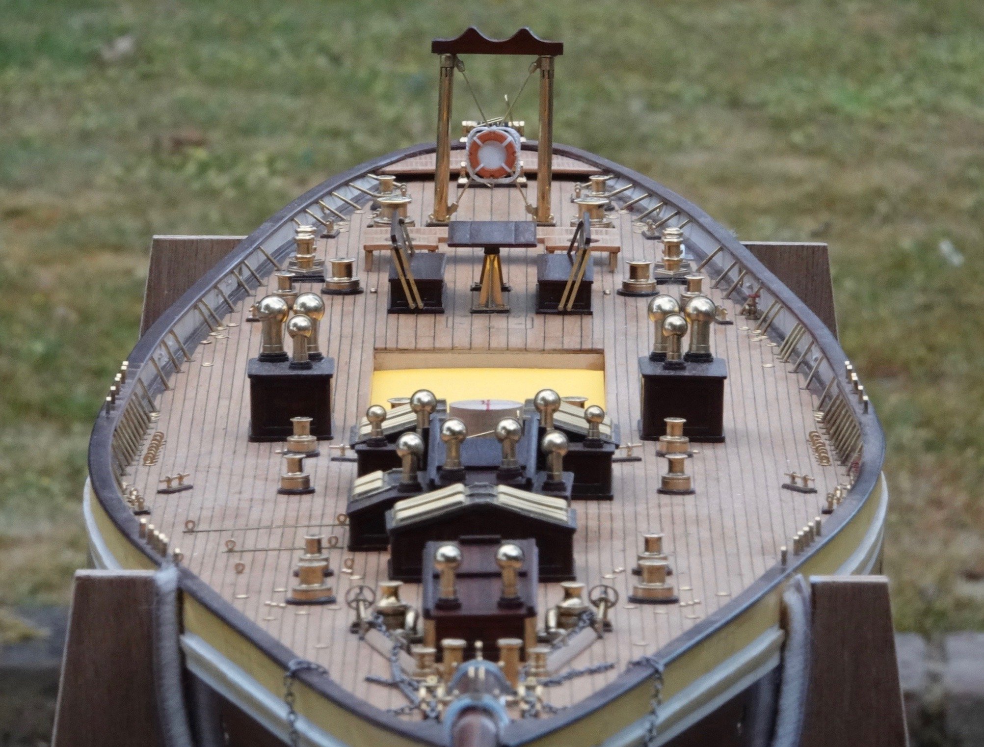
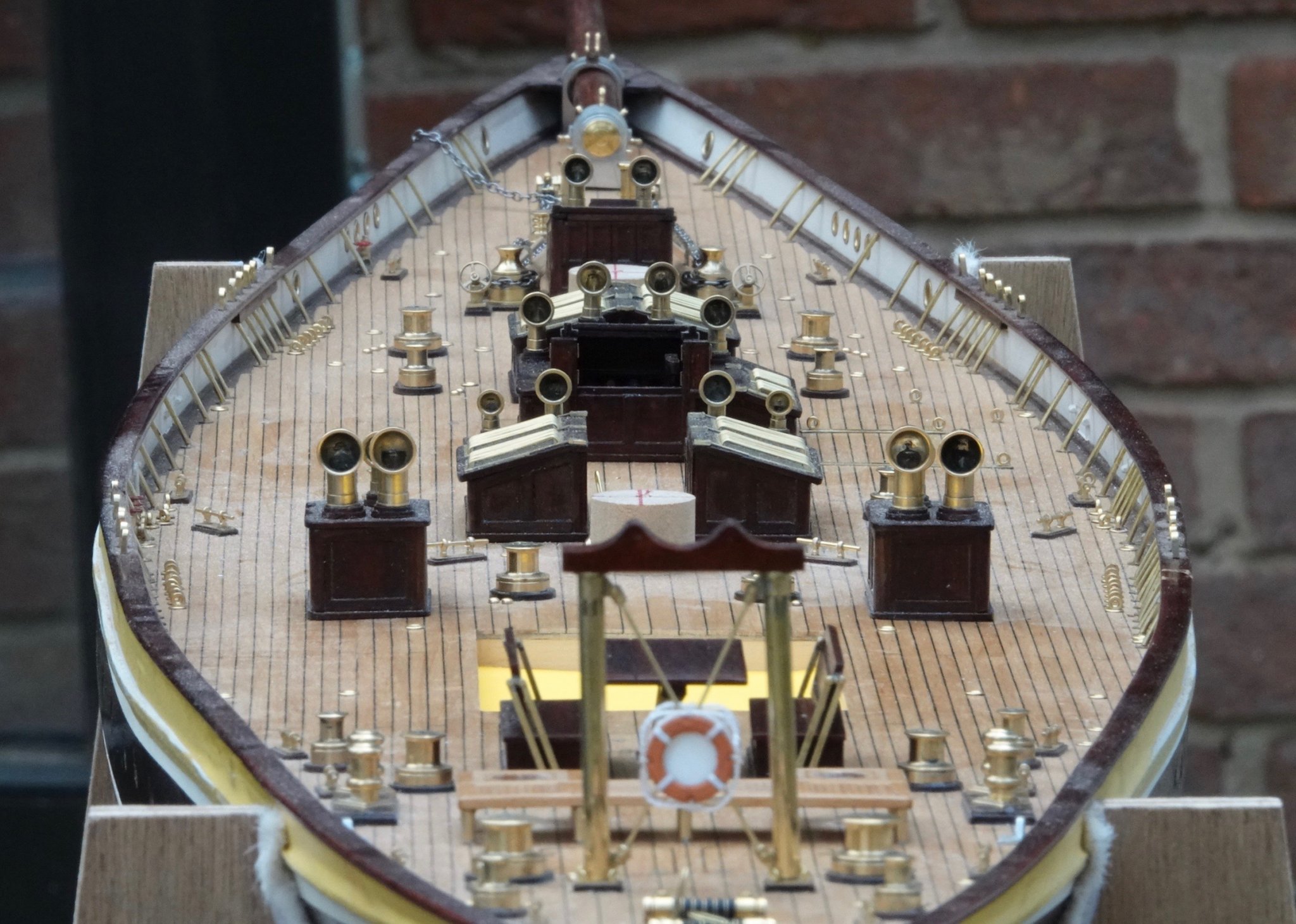
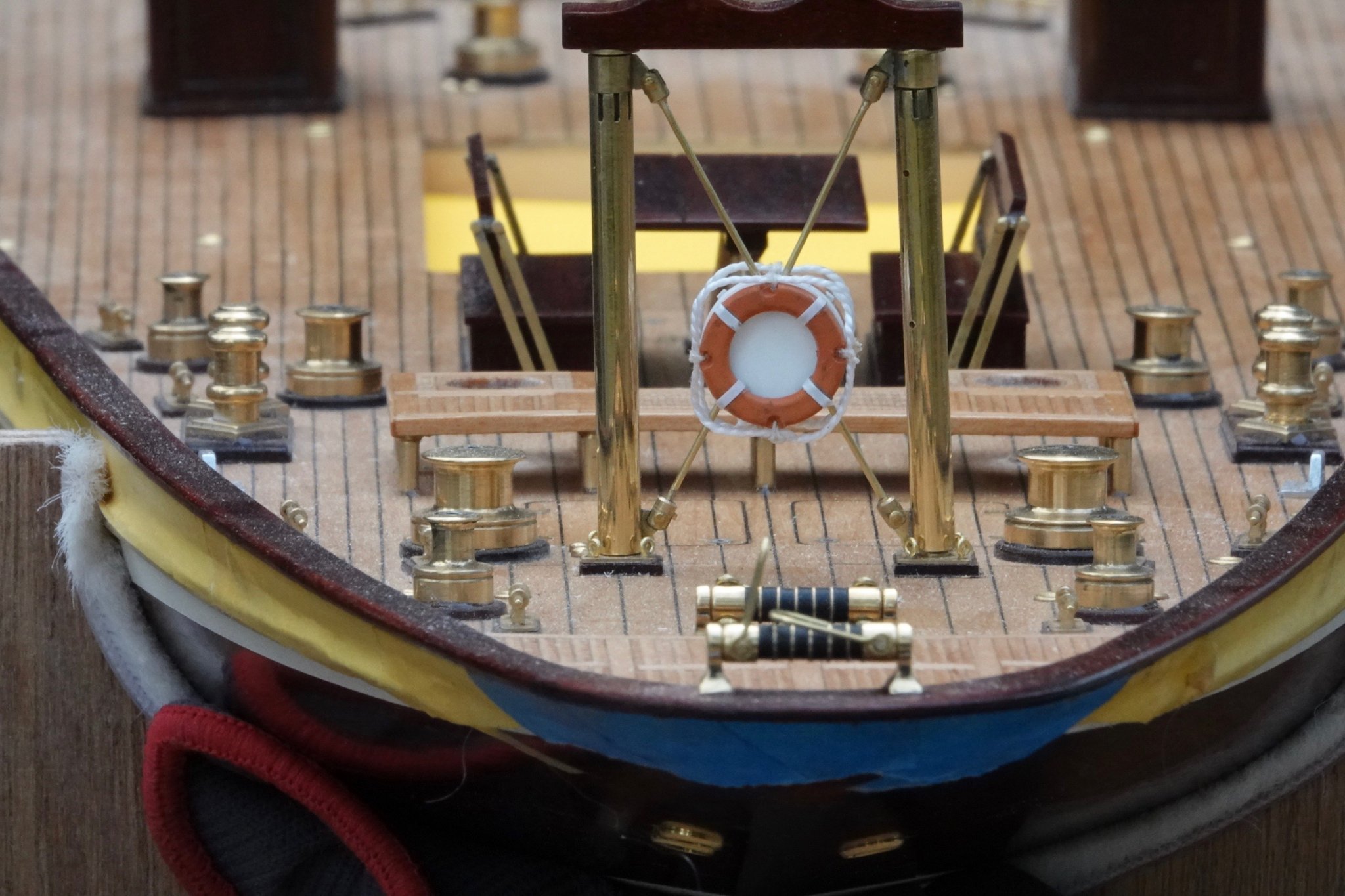
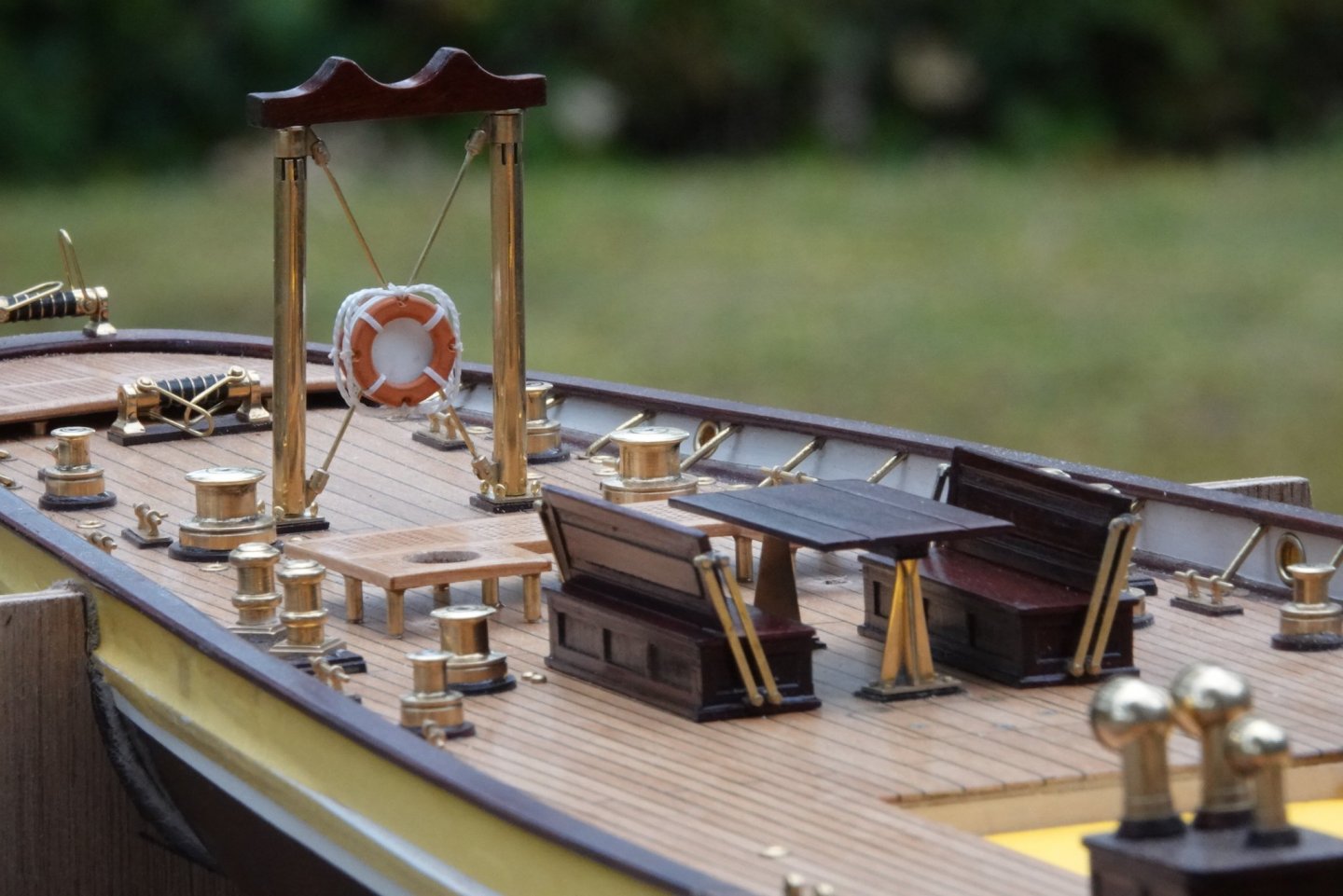
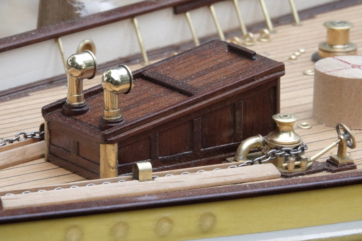
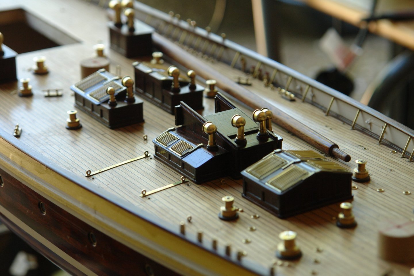
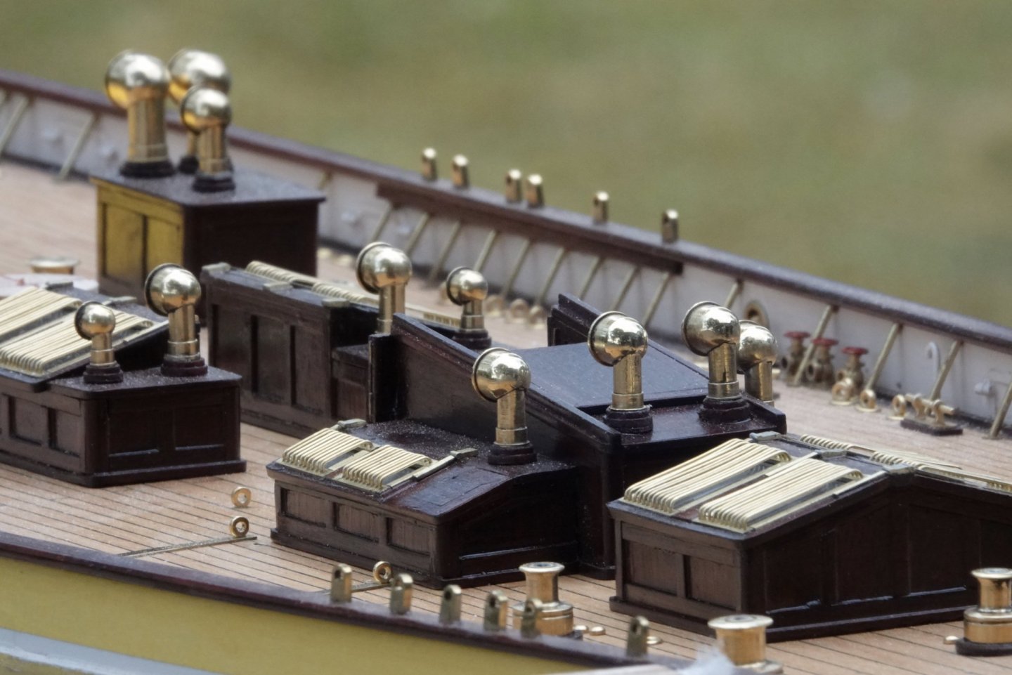
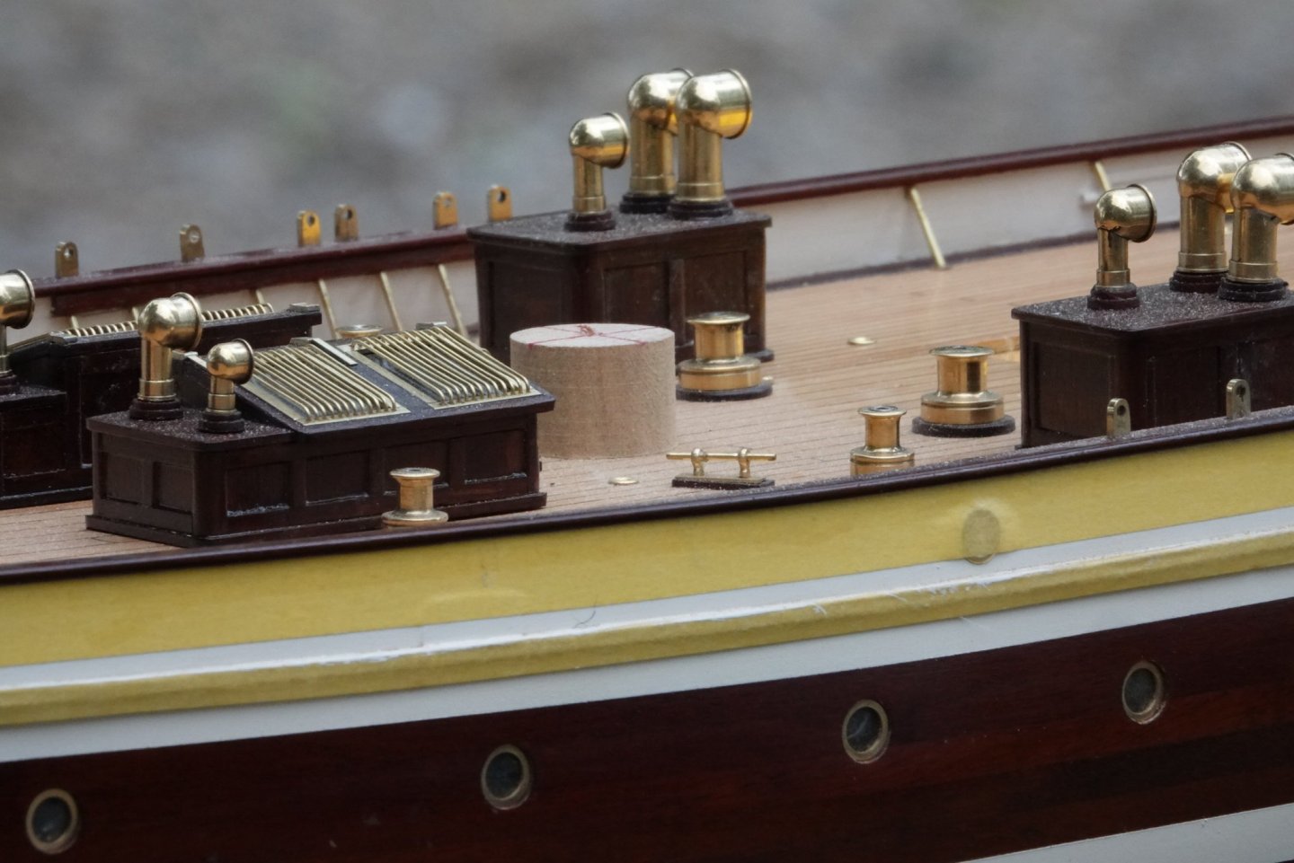
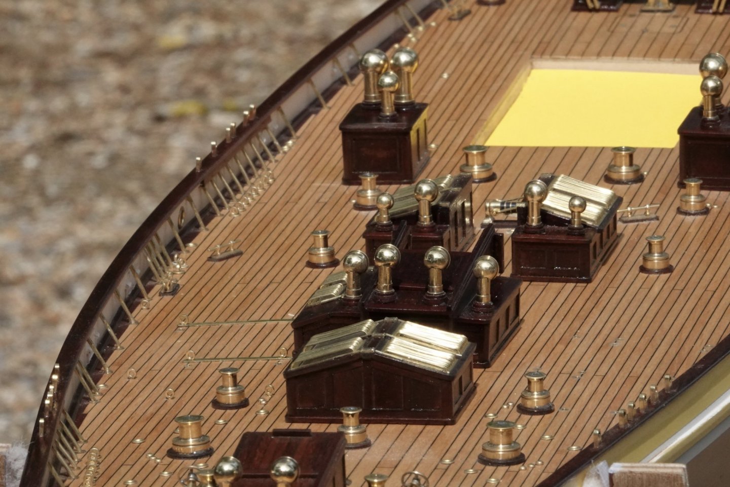
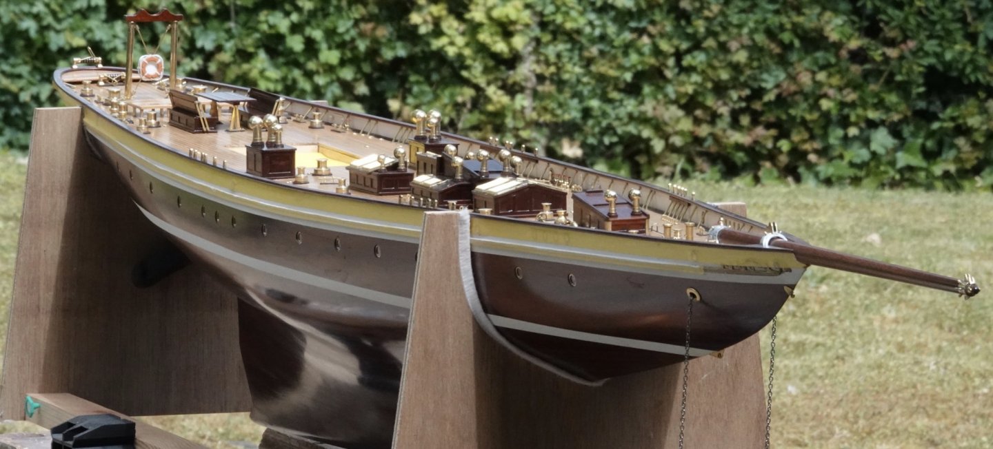
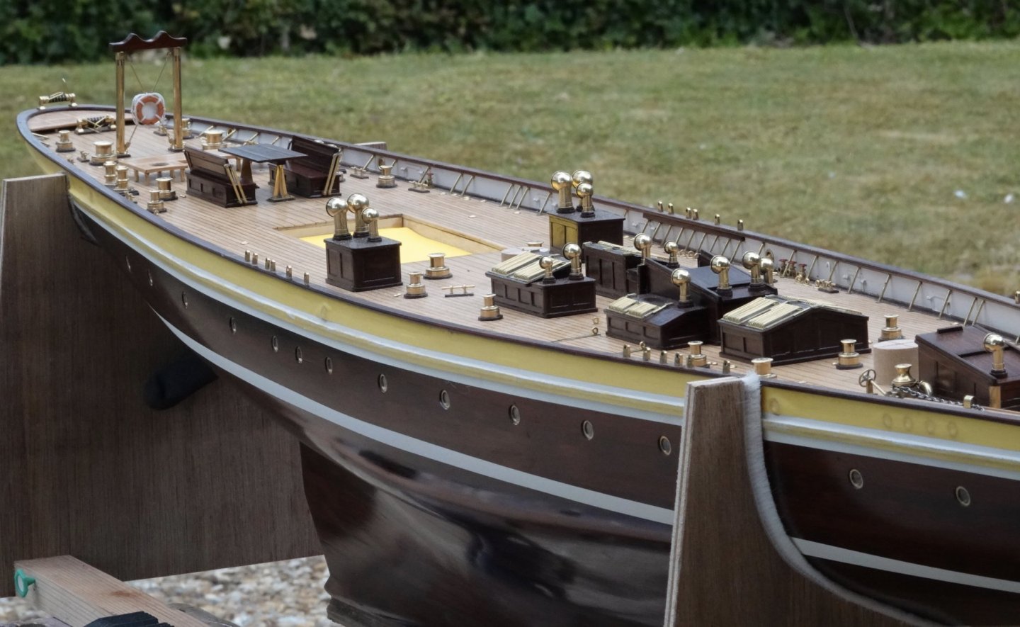
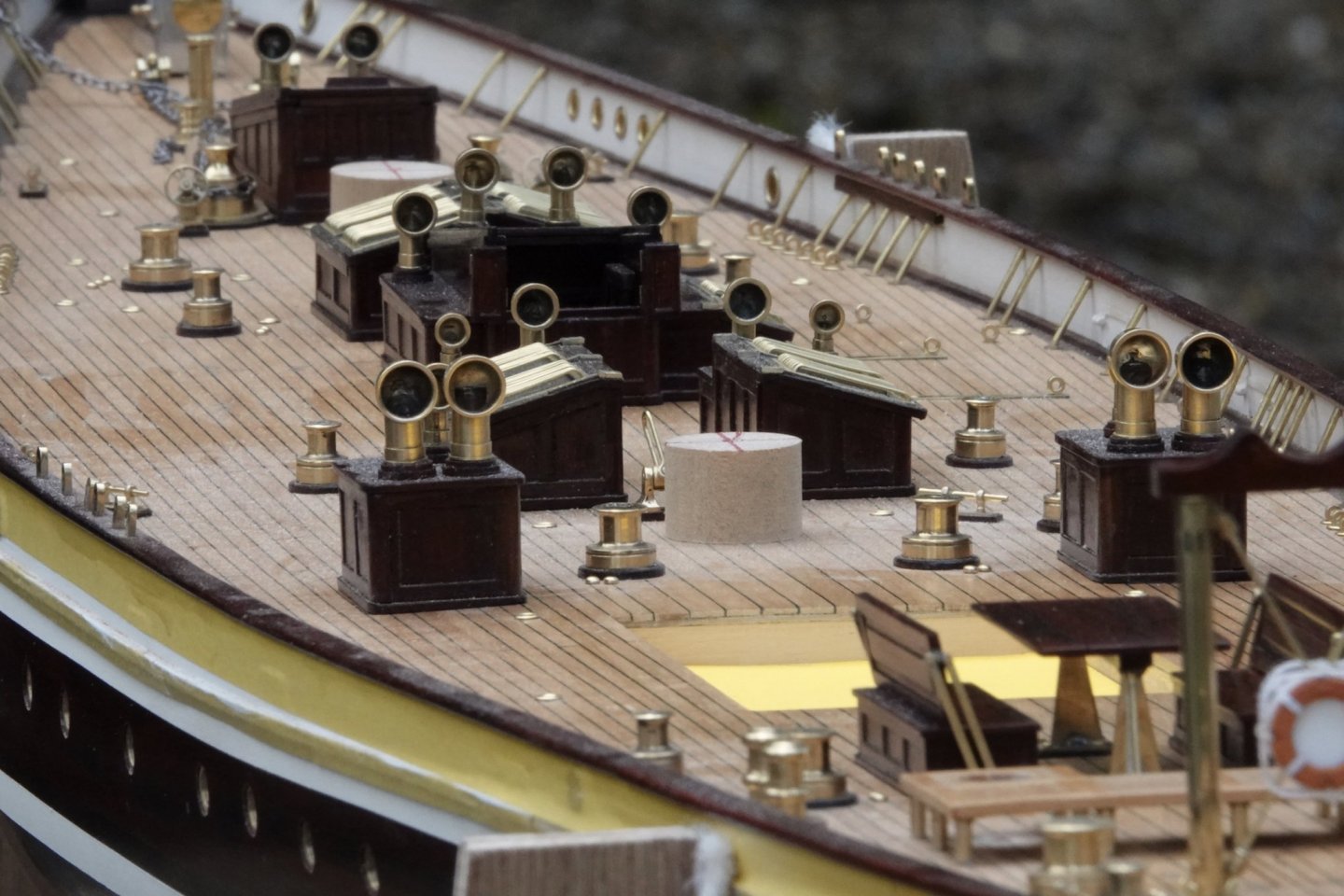
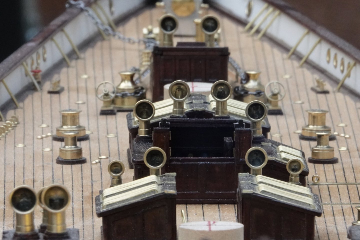
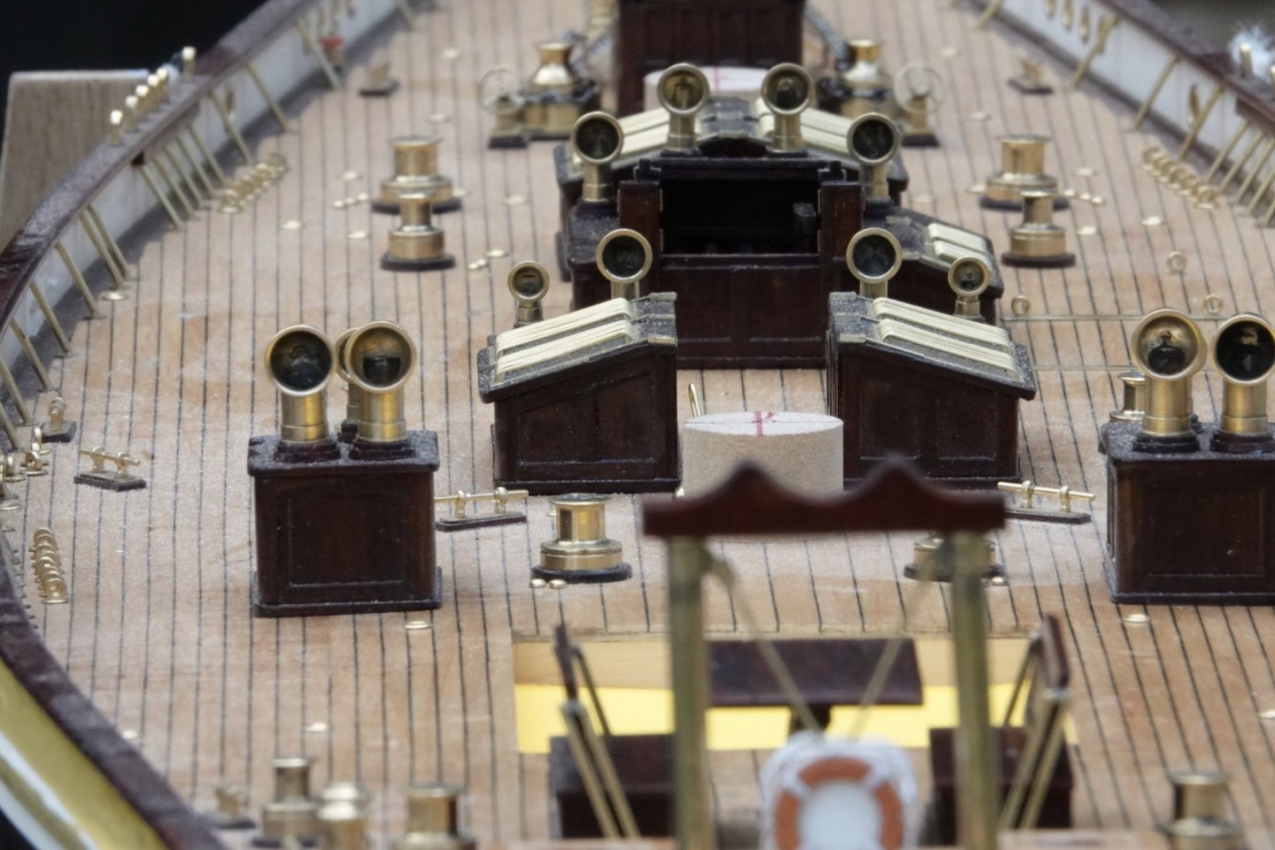
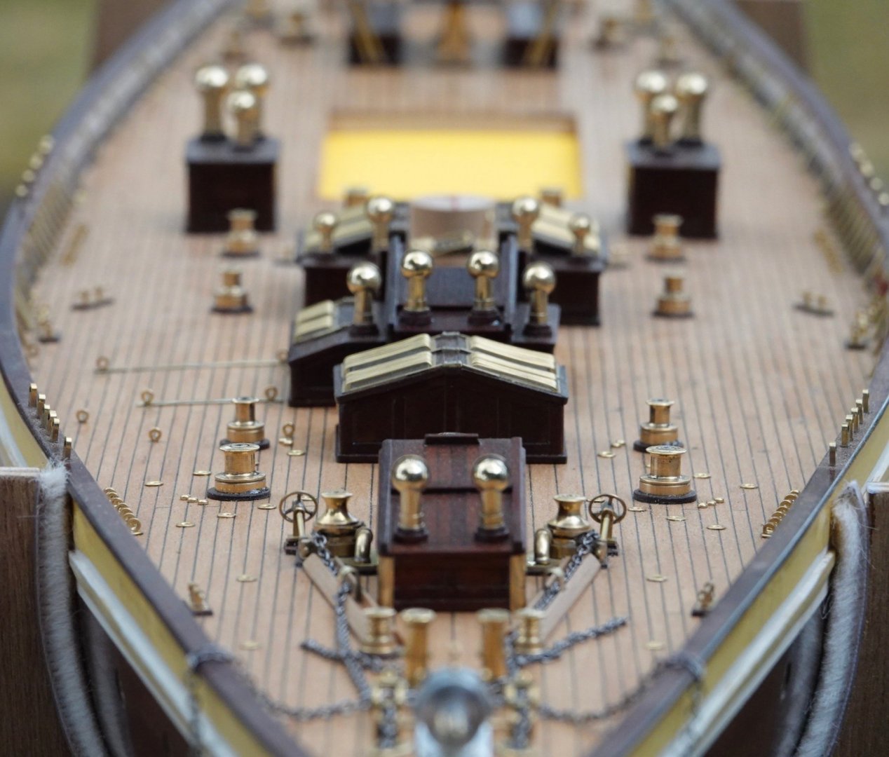
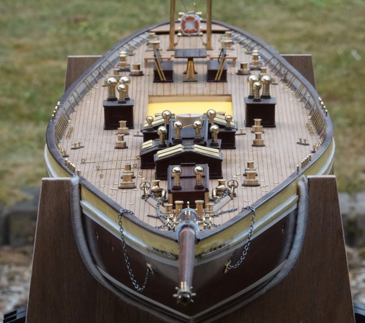
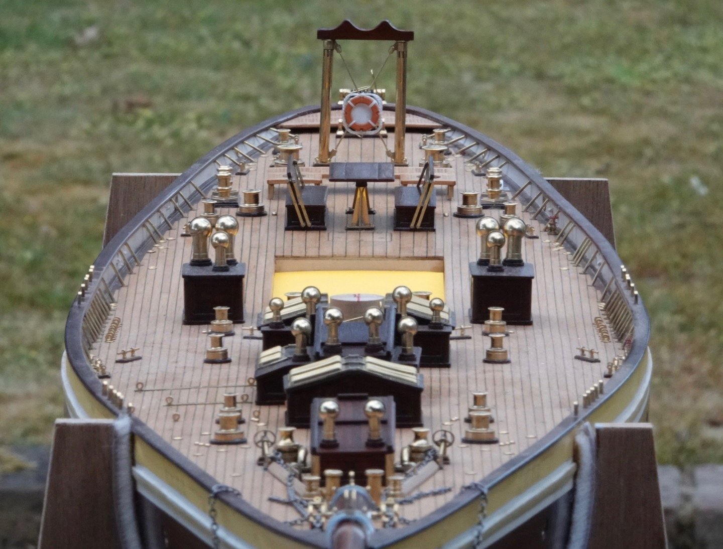
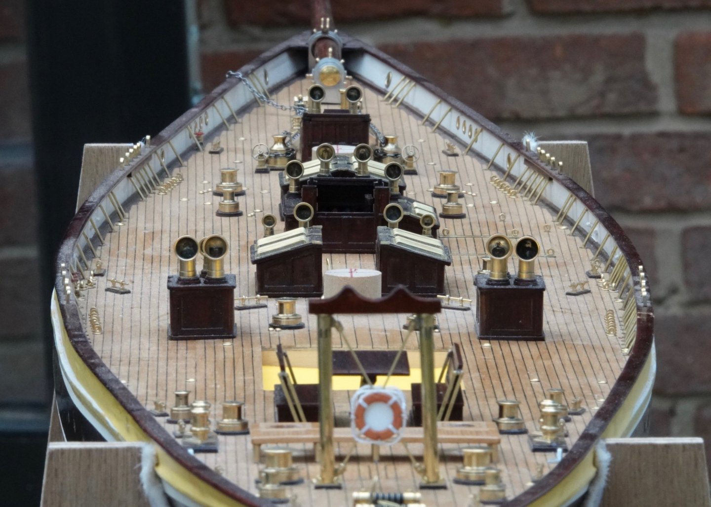
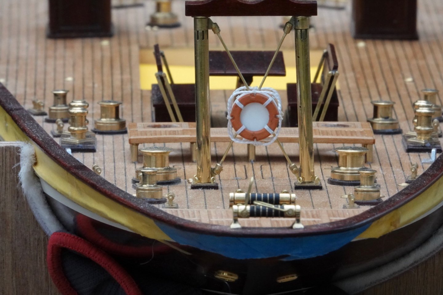
Eberhard, Chris, Druxey, Richard - thank you all for your comments. Also thanks to everyone for all the likes I made the plinths for the vents and then mounted the vents by inserting spigots into the bores of the stems. I took a lot of photos. I will post these a few at a time over the next few days. I haven't sorted out the rope ears on the life ring yet. The yellow card is a temporary dust shield - I am getting fed up with cleaning out below decks.
-
Eberhard - the mill was ground with the cutting edge all the way to the centre (almost like a wist drill). I did do one cowl with just the mill and it worked ok, but the pressure seemed a bit on the high side. Using a centre drill to about 3/4 the required depth just seemed to make the cut a little easier. Keith - the insides are all brass but I don't think they get polished. Ships cowls are generally made from steel plate and hence need painting (inside and out) to avoid corrosion. I am not sure why the insides are frequently painted red but maybe it relates to the use of red-lead oxide paint. Thank you both for commenting.
-
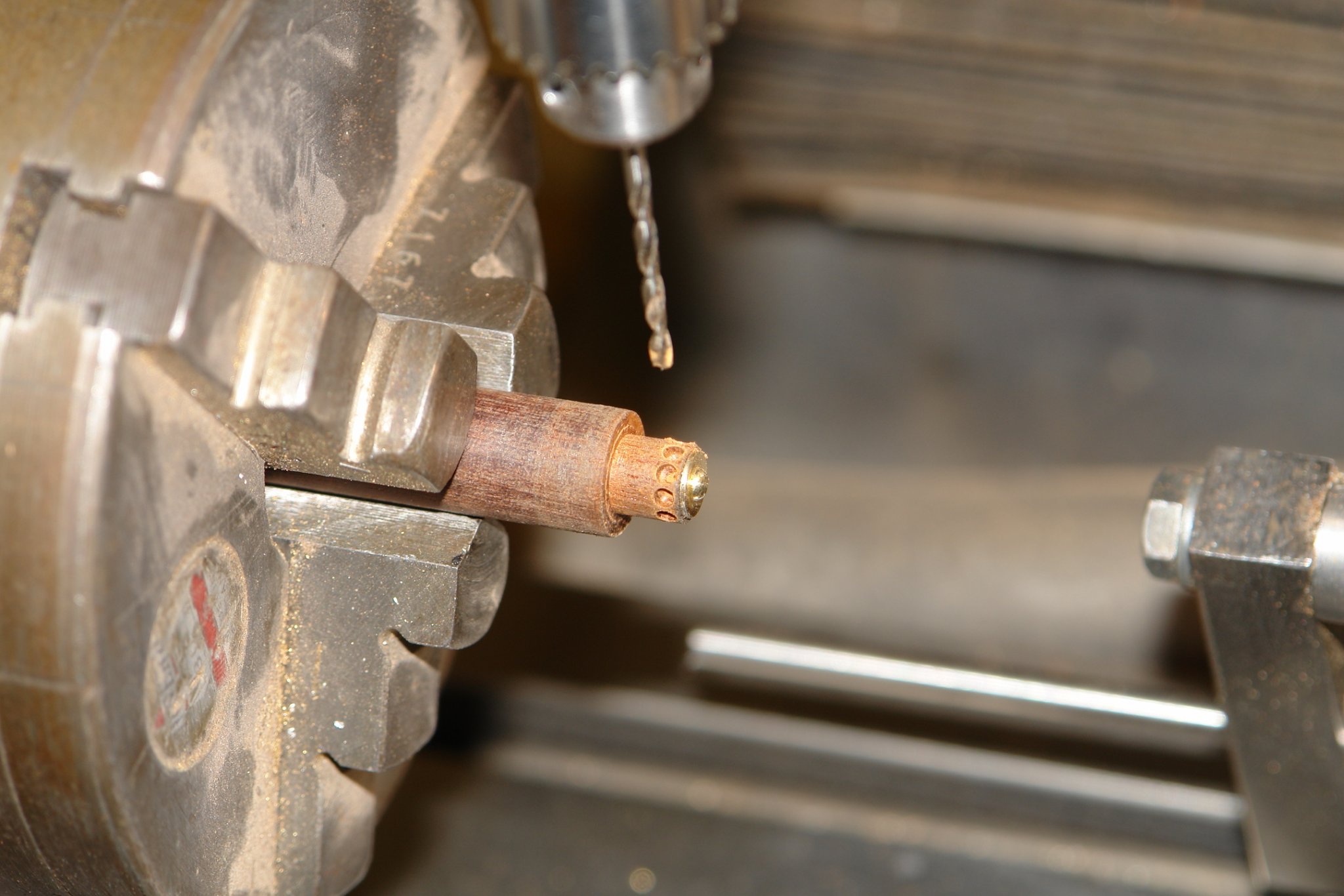
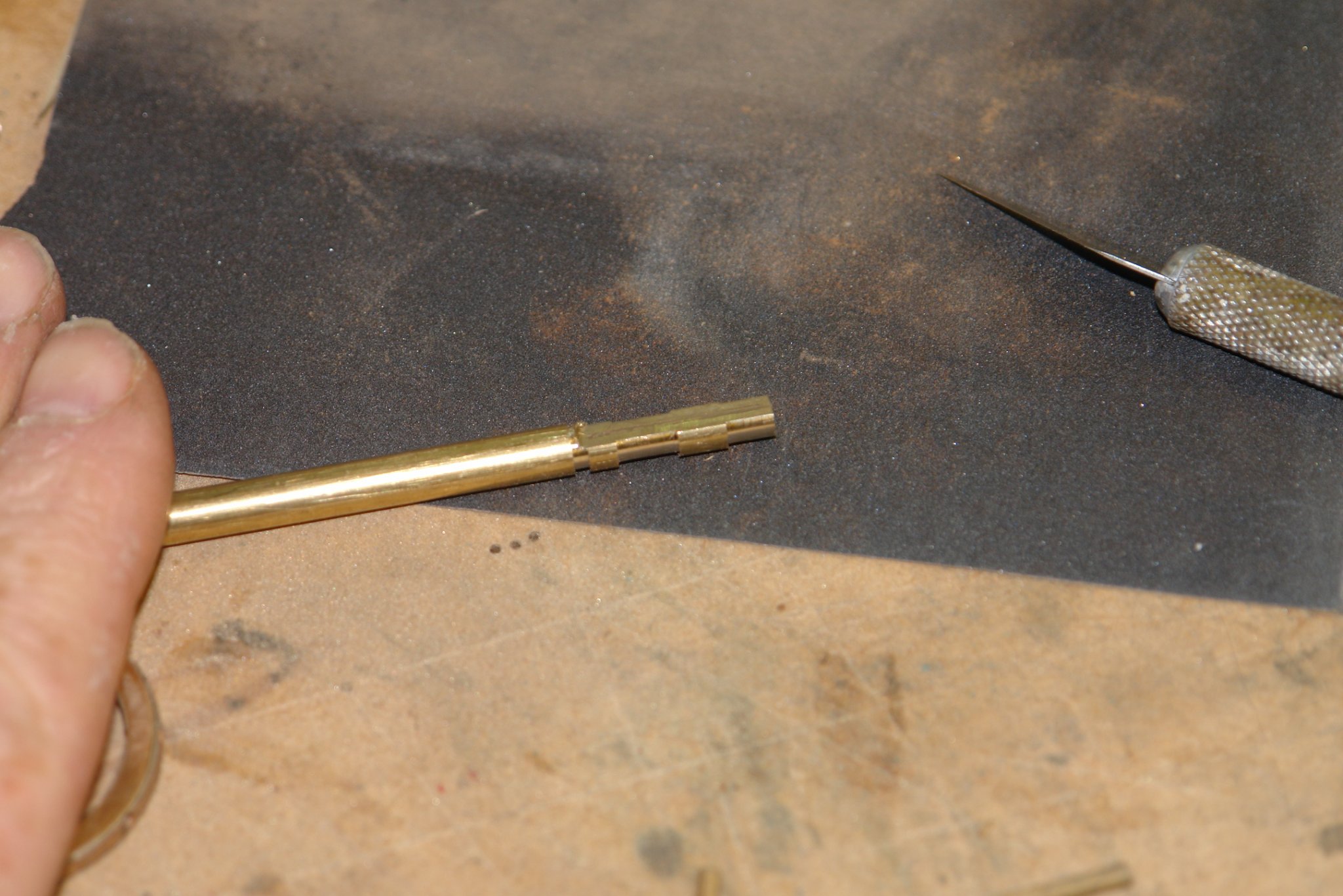
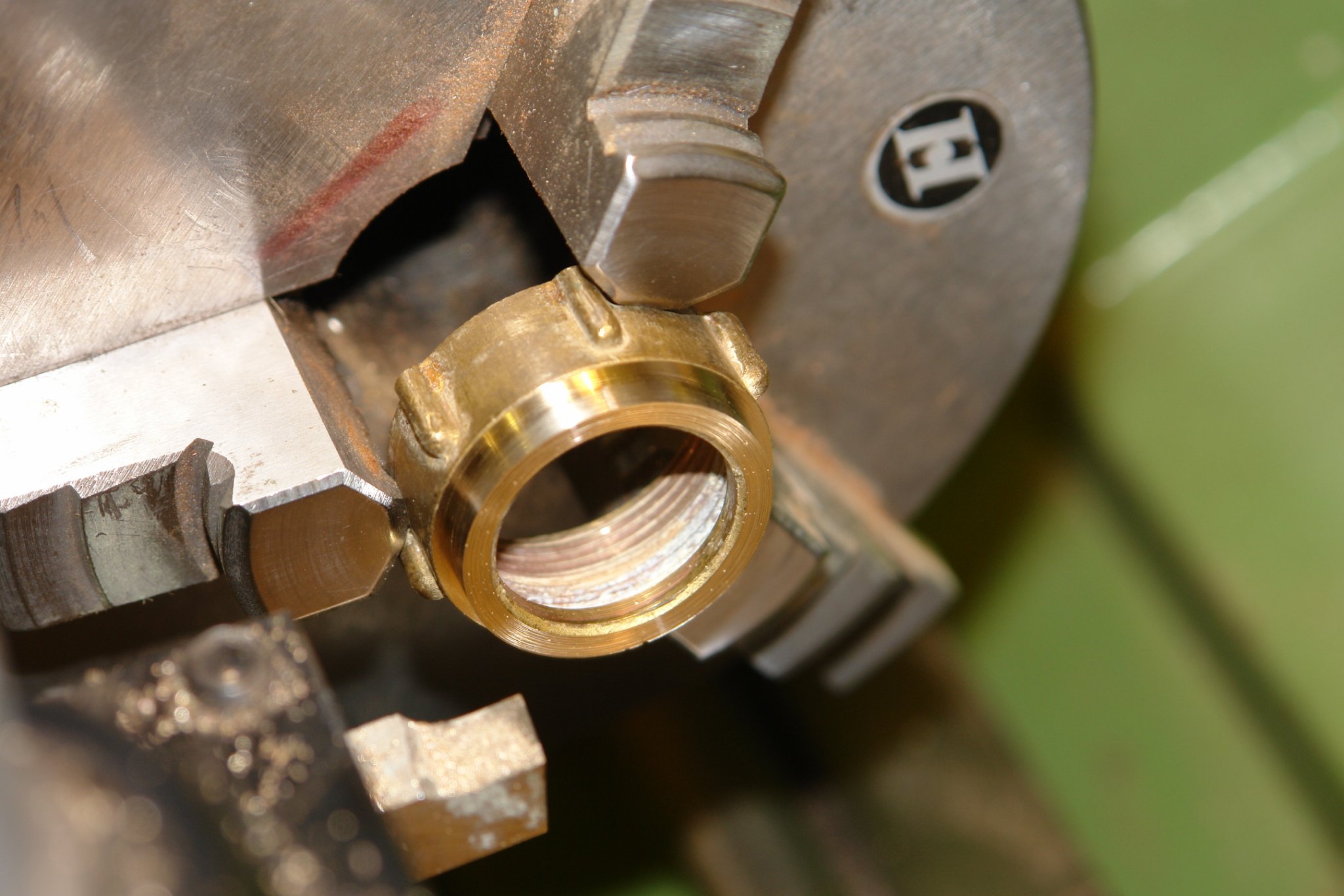
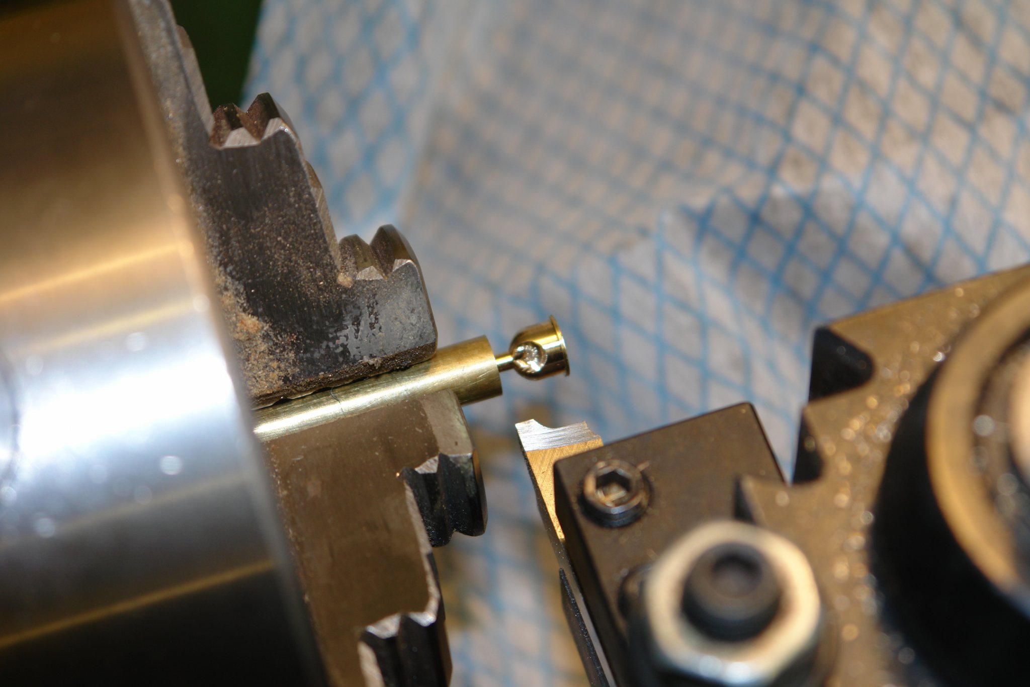
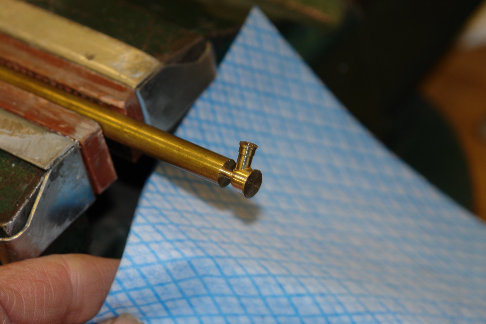
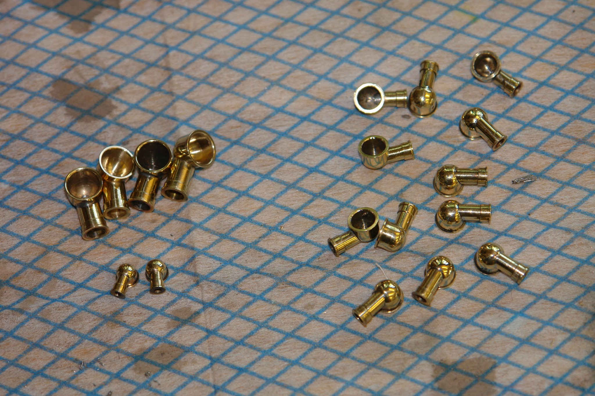
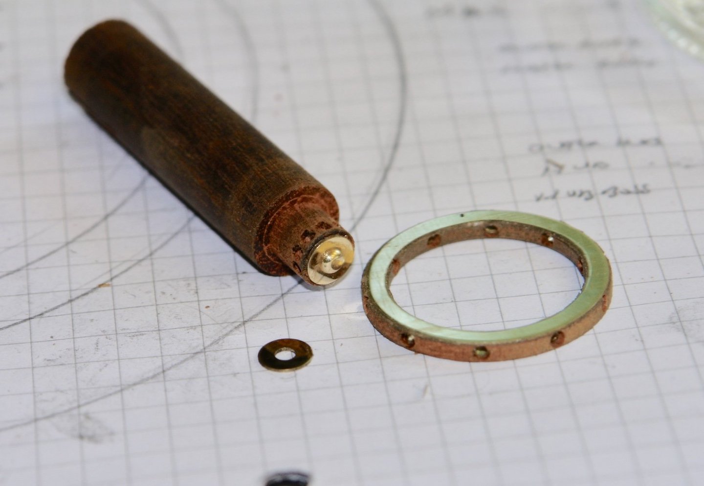
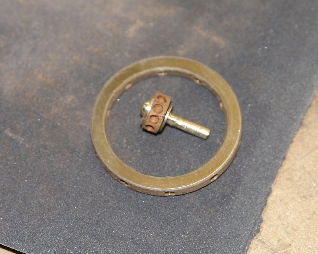
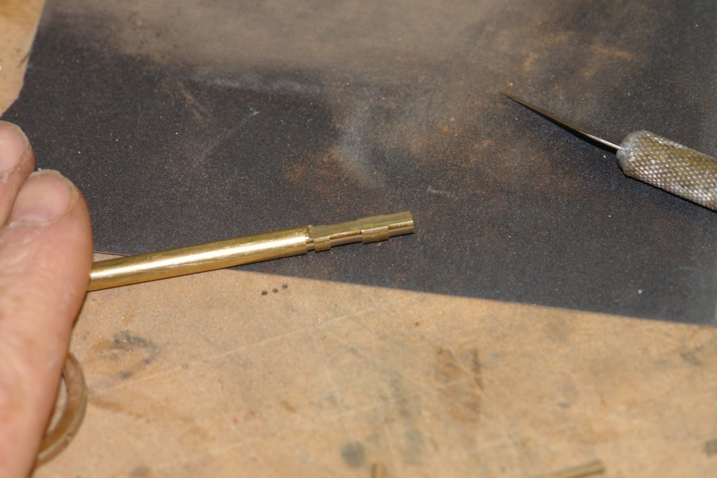
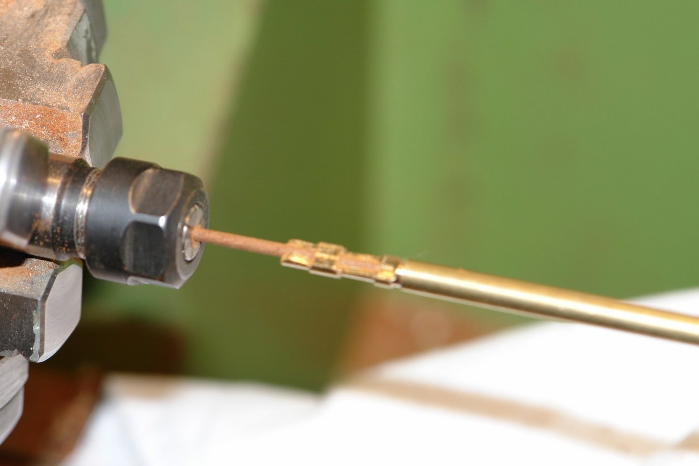
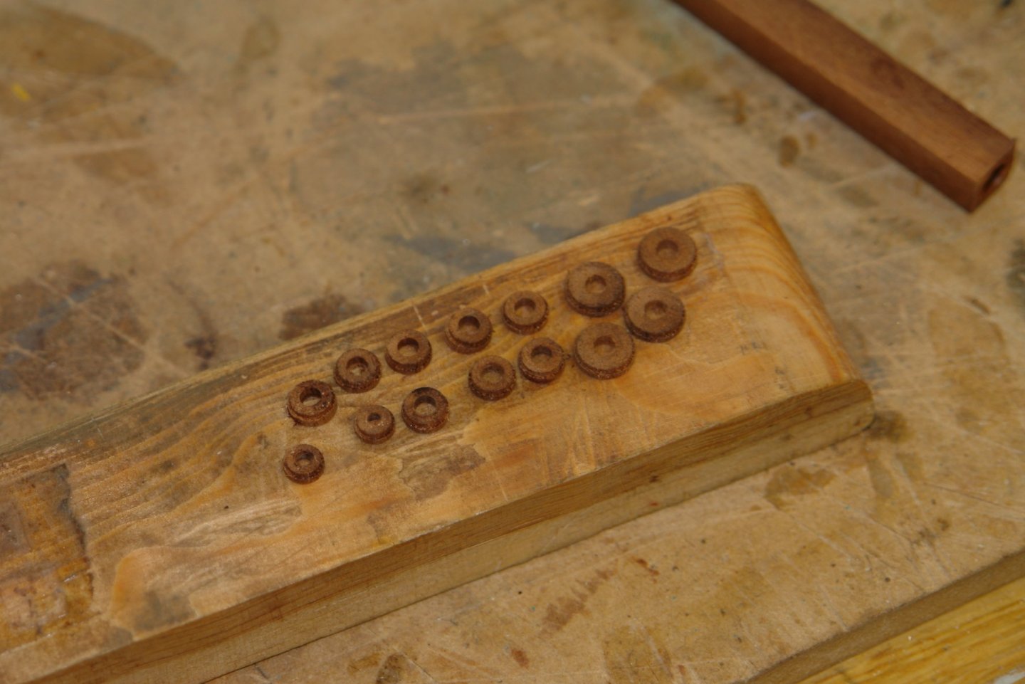
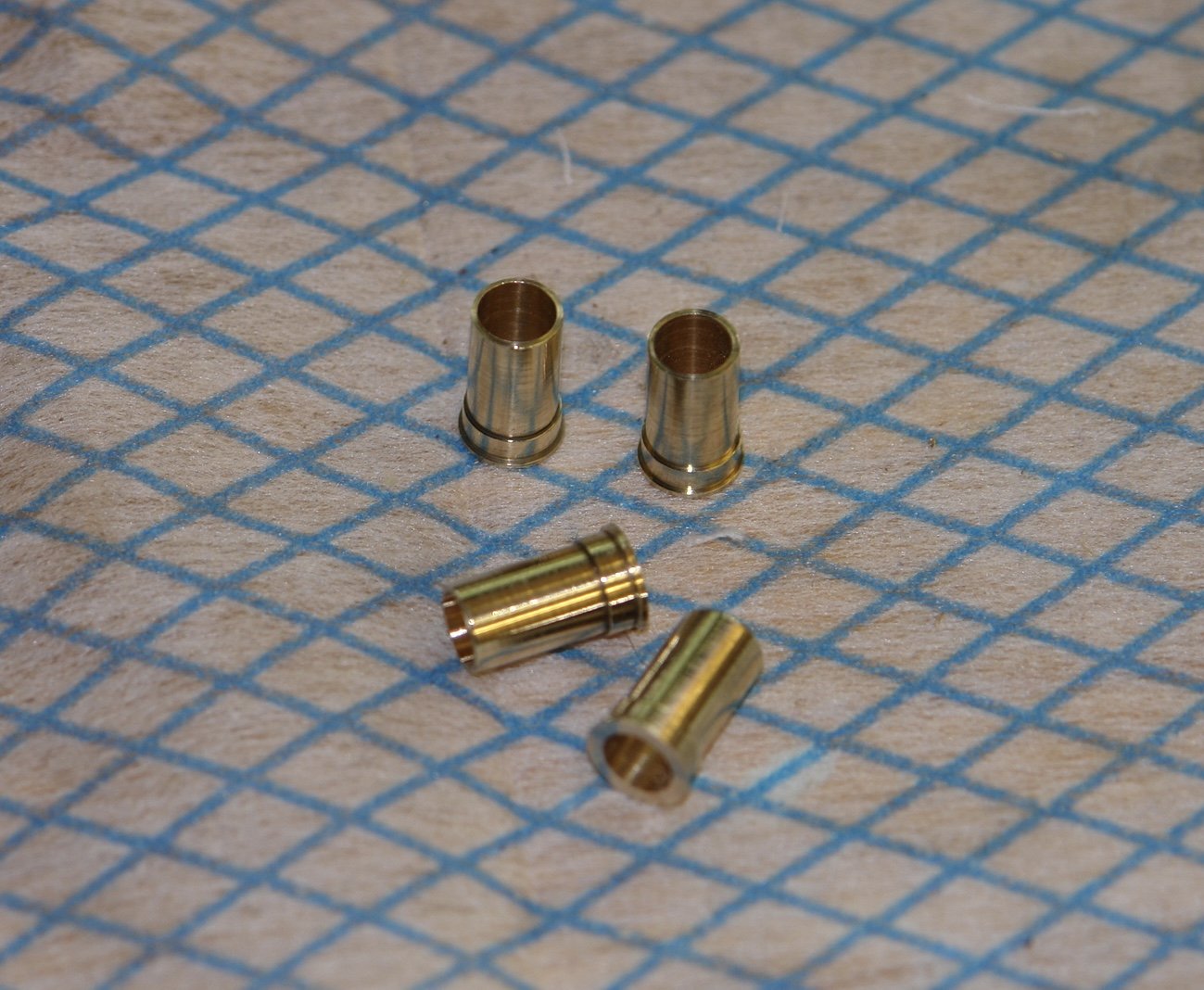
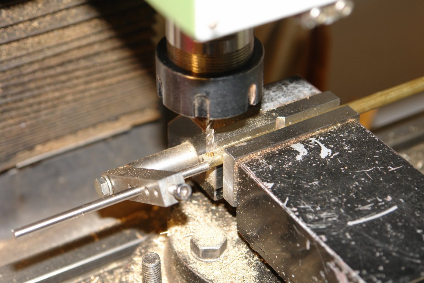
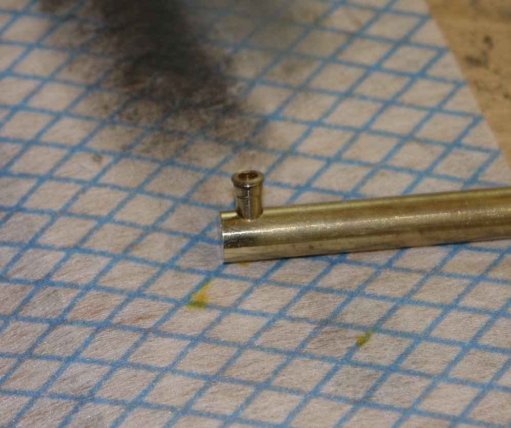
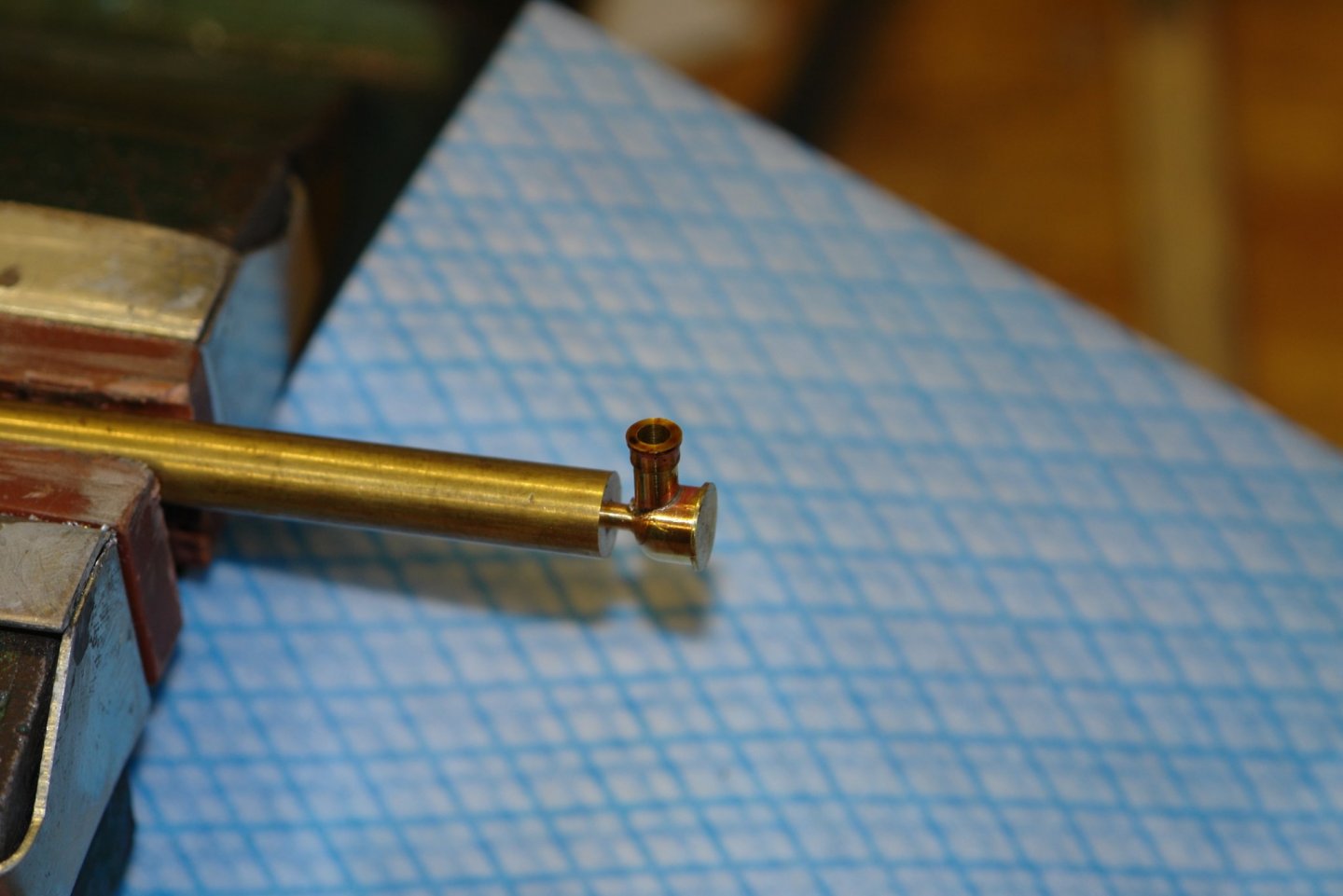
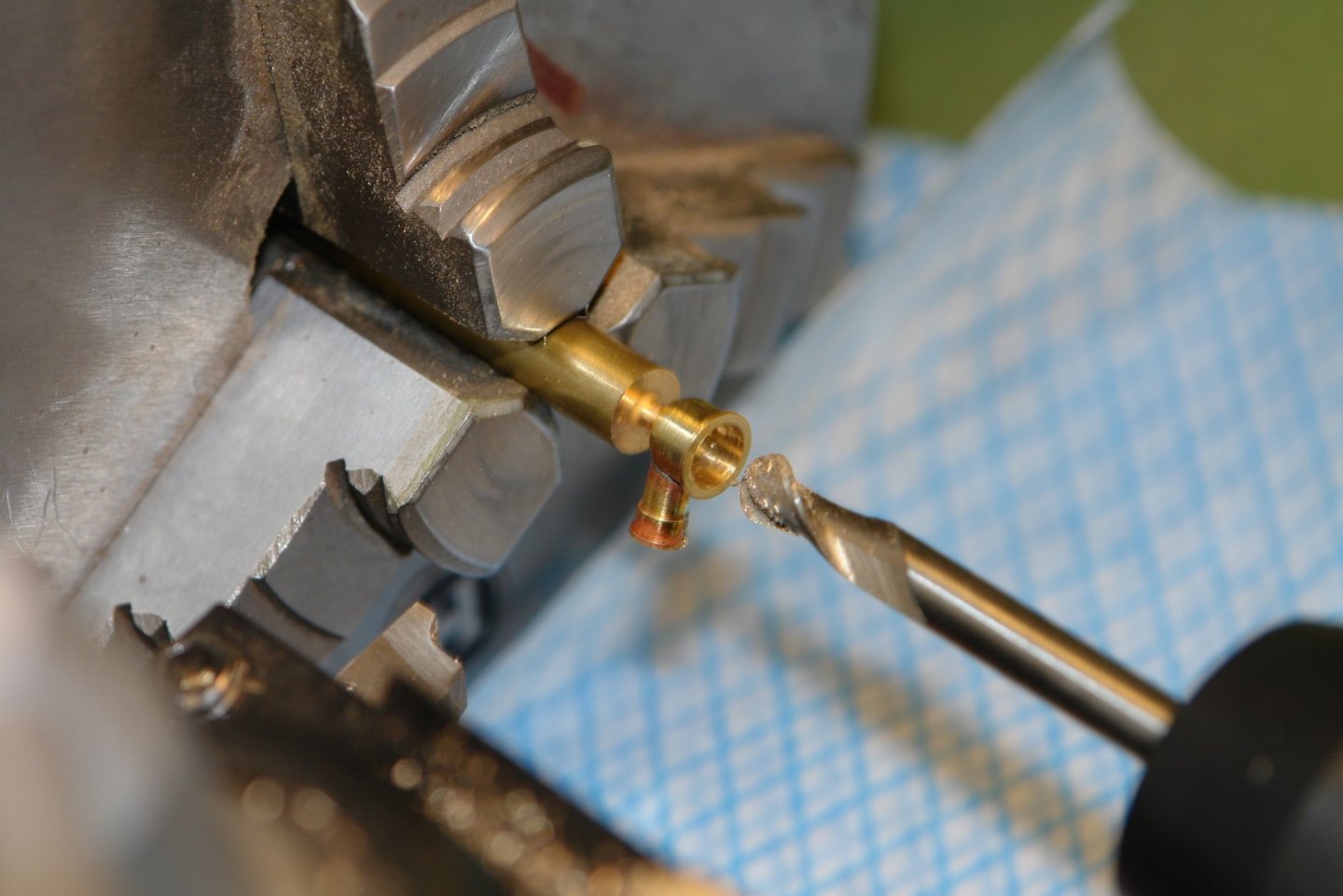
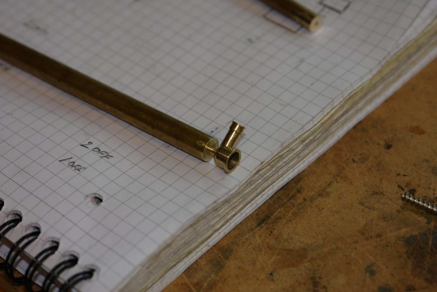
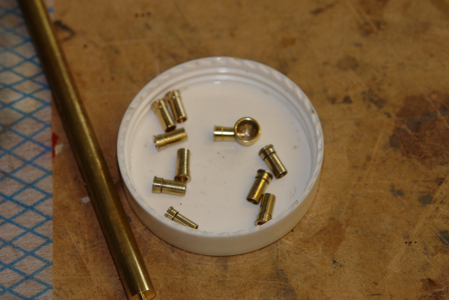
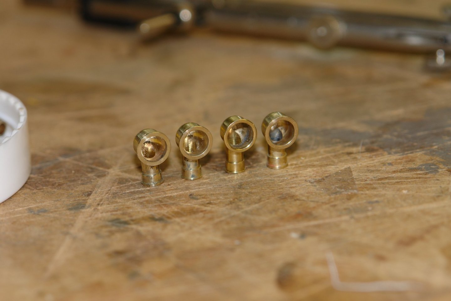
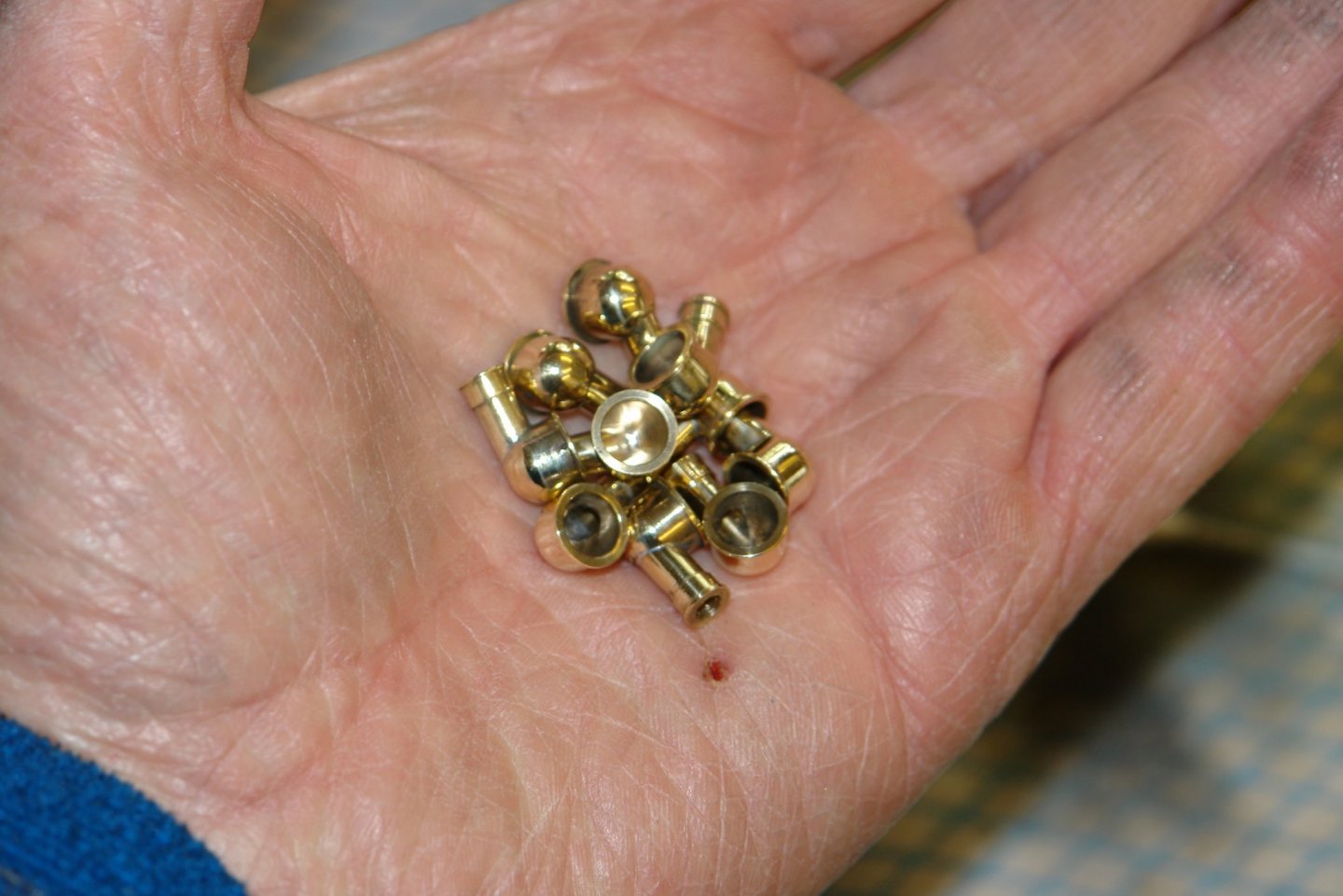
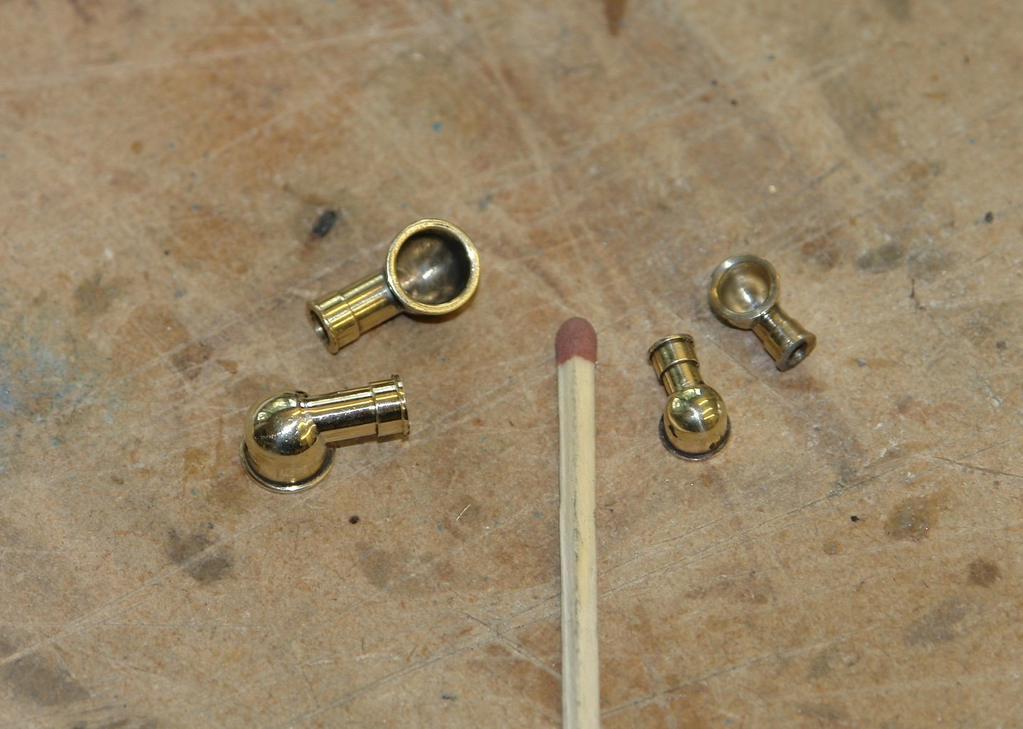
Vents:- I started off by making all the stems - the ones in the next photo just happen to be the 4 largest ones. The next sequence of photos covers the manufacture of the cowl. Starting with the drilling and milling of the holes to take the stem. The end stop is set on the milling vice so that all holes for a specific size of cowl are subsequently drilled the same distance from the end of the bar. In the next photo the stem inserted to test the fit. The stem is removed and the outer profile of the cowl is machined using the profile tool. The tool is advanced very slowly to minimise cutting forces. The tool position is set such the the radius of the profile is at the left hand edge of the hole drilled in the bar. The bar is then removed form the lathe and the stem is reinserted. A small piece of solder is placed in the bore of the stem and the assembly is heated to melt the solder. This produces a neat solder joint with no excess solder to clean from the outside of the cowl. Then its back to the lathe to bore out the cowl mouth. I found that drilling a small pilot hole eased the passage of the ball ended end mill. The small spigot holding the cowl to the bar is then cut off and then finished with a file and emery cloth before polishing. I started with the middle sized cowls. The first one took about an hour. In the next photo you can see the completed cowl with 9 other stems. I had miscounted when making stems and had to go back later and make 2 more. I took a celebratory photo when I got to 4. By this stage manufacture time was about half and hour. By the end of day 1 I had the 12 middle sized ones complete. I then made the 2 smaller ones - not very big at all. I then moved on to the 4 larger cowls. By the end of day 2 I had 18 all made.


-
Great to see something quite different. Very interesting and enjoyable. Thank you.
- 81 replies
-
- 2
-
-
- egyptian
- byblos ship
- (and 1 more)
-
found this on you tube - quite a feat of endurance. https://www.youtube.com/watch?v=Z5IT90vZBRo
-
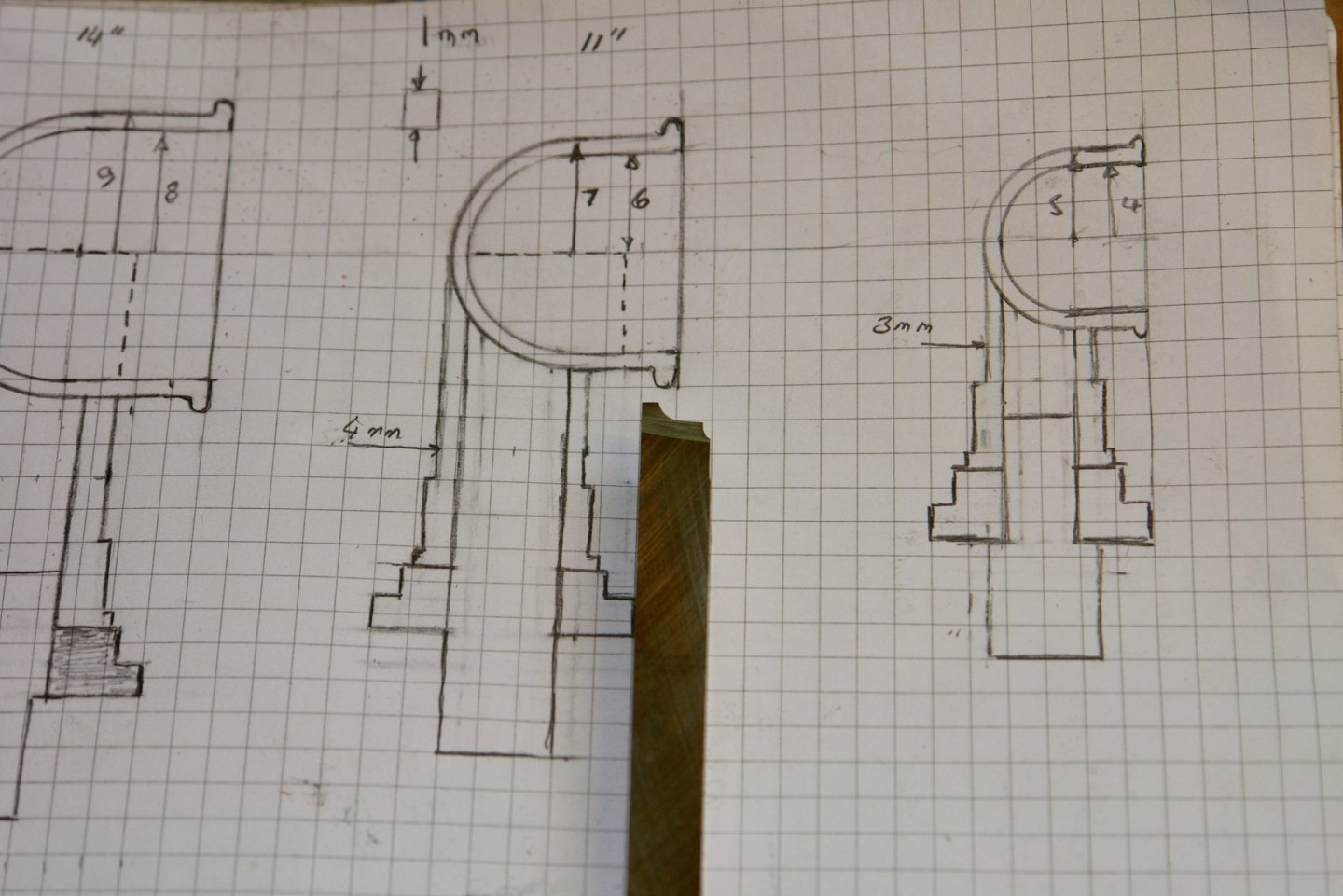
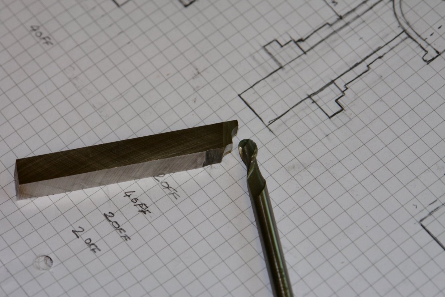
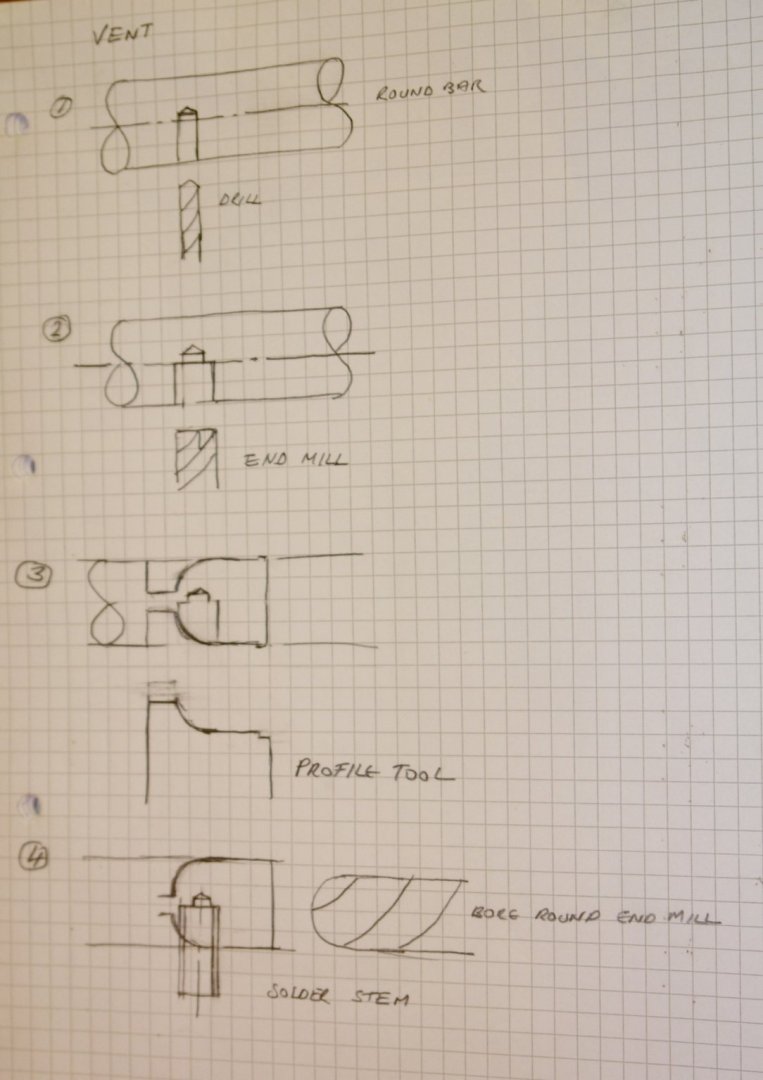
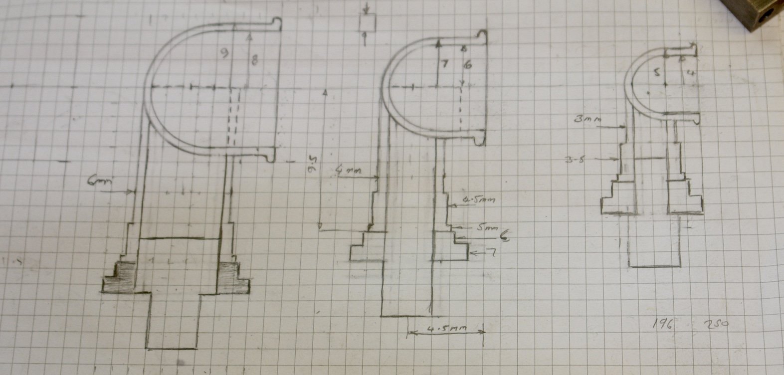
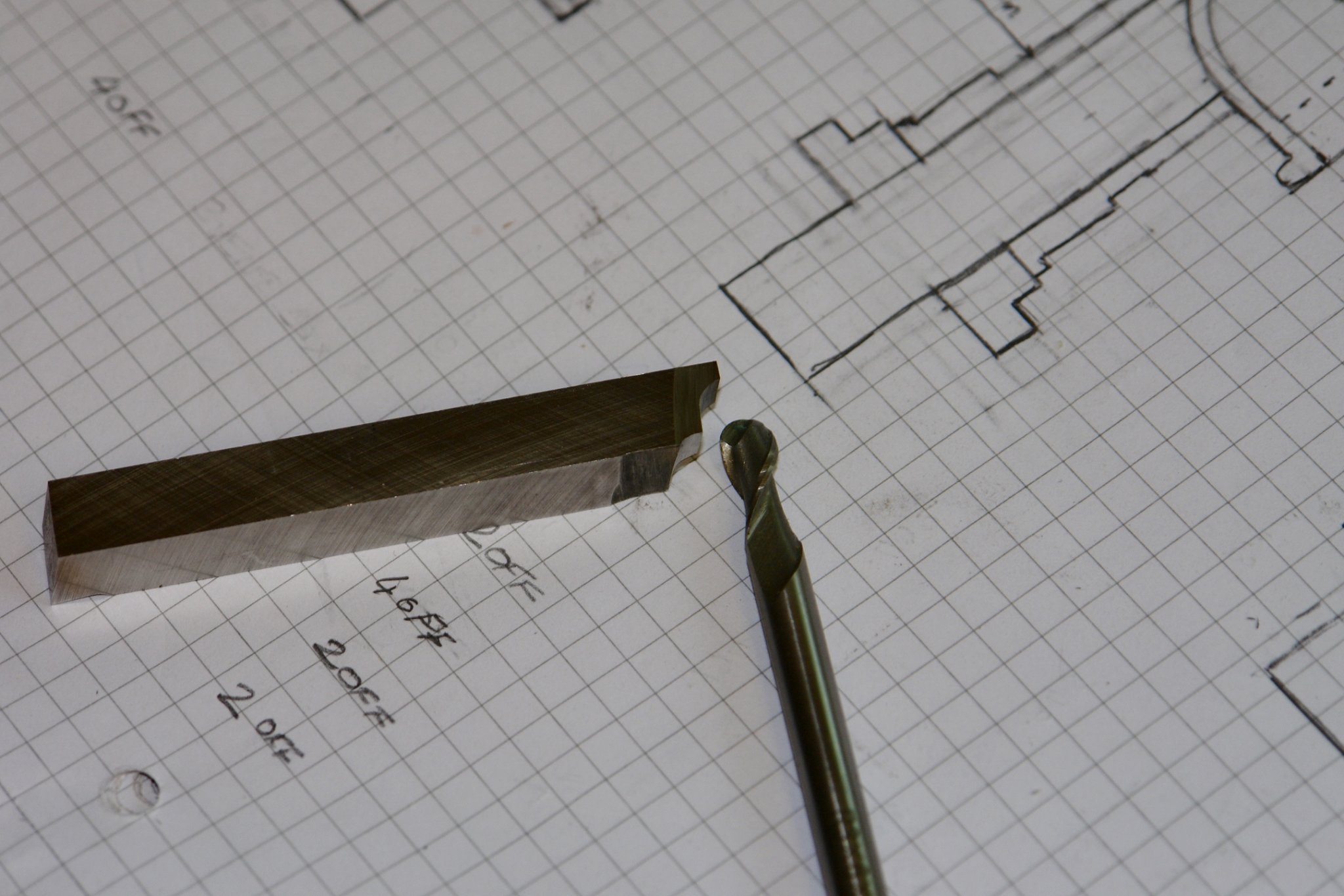
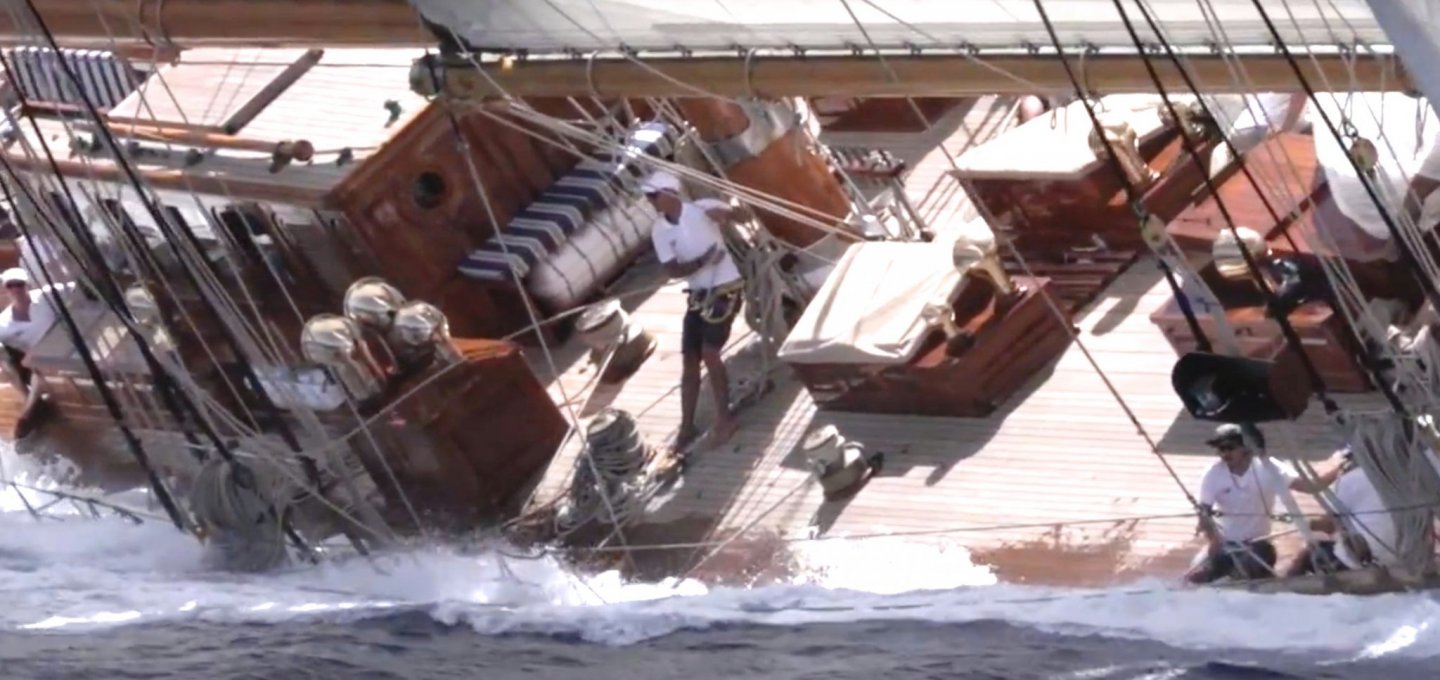
Pat, Druxey, Mark, Geert, Richard - thank you all for your kind comments. Mark thank you for your feedback. I can see my brackets are worrying you. Before the end of the build I am hoping more Germania photos will come to light and then perhaps we will all find out the purpose. Your guess may well be correct. And so on to the vents. One of the things that attracted me to starting Germania was there plethora of ventilation cowls, seemingly totally over the top and to my eye very teutonic. As usual with me I had imagined them to be much bigger than they turned out to be. Somehow the scaling of photographs proved quite difficult and I had to repeat the exercise several times using about 10 different photos before I was happy. The following photo is the one showing most vents but there are number more. The good news about the vents is they are a fairly simple shape - essentially the mouth is a dome ended cylinder while the stem is another cylinder. My mammoth attempt at scaling convinced me that three different sizes of vent exist. The following sketch reflects these. Sorry but the scale is metric and each square is 1mm x 1mm. The larger size has a 8mm (.32") mouth and a 6mm (.24") stem - 4 of these are required. The middle size has a 6mm (.24") mouth and a 4mm (.16") stem - 12 of these are required. The small size has a 4mm (.16") mouth and a 3mm (.12") stem - 2 of these are required. I plan to fabricate them as follows:- Step 1 - is to take a round bar and machine the outside diameter to size. Then drill a hole just over half way through the bar. Step 2 - is to take an end mill the same diameter as the the stem outside diameter and widen out the hole to a depth equal to the bars radius. Step 3 - is to turn the outside profile of the vent mouth using a profile tool. Step 4 - is to insert the stem and solder it in place, Followed by boring the inside of mouth using a ball ended milling cutter. For each size of vent the wall thickness will be 0.5mm (.02"). I made the 3 profile tools by grinding high speed tool steel by hand, it took time and patience to get them right. The next photo shows the profile tool for the middle sized vent. Here is the profile tool with its corresponding ball ended mill. Tomorrow I commence the production run - hopefully by Sunday evening I will have 18 vents.