KeithAug
-
Posts
3,986 -
Joined
-
Last visited
Content Type
Profiles
Forums
Gallery
Events
Everything posted by KeithAug
-
 John - tried that and made a mess of it - probably need to give it another go. Thinking about it now I could make long rolls and then just cut off short lengths - will give it a try.
 -
JD - not been called that before - at the moment feels more like convict Keith. I look forward to your next post.
-
John ----- Hmmmmm! thereby lies a problem. I tried printing flags on paper and then rolling them up and putting them in the pigeon holes. They were so small they looked a mess - Not sure what to do.
-
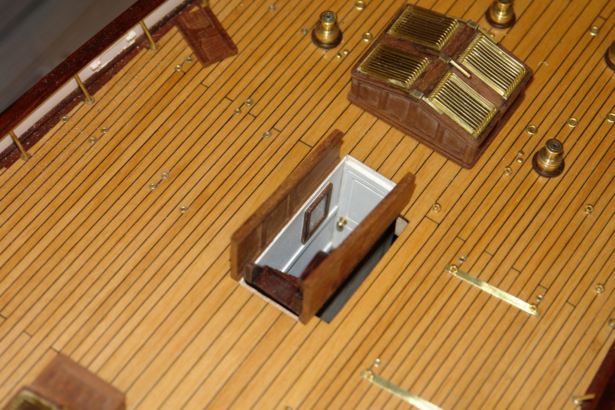
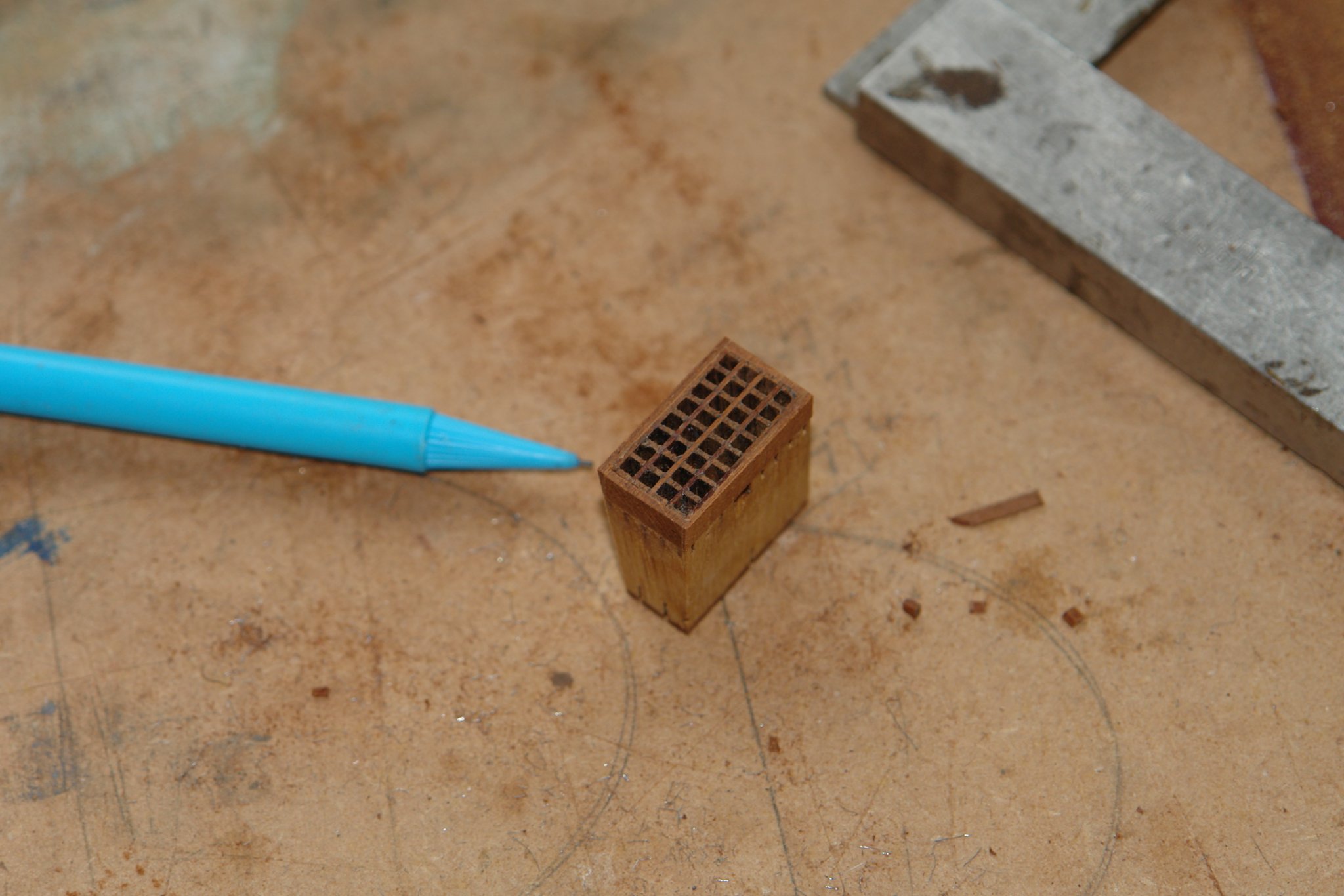
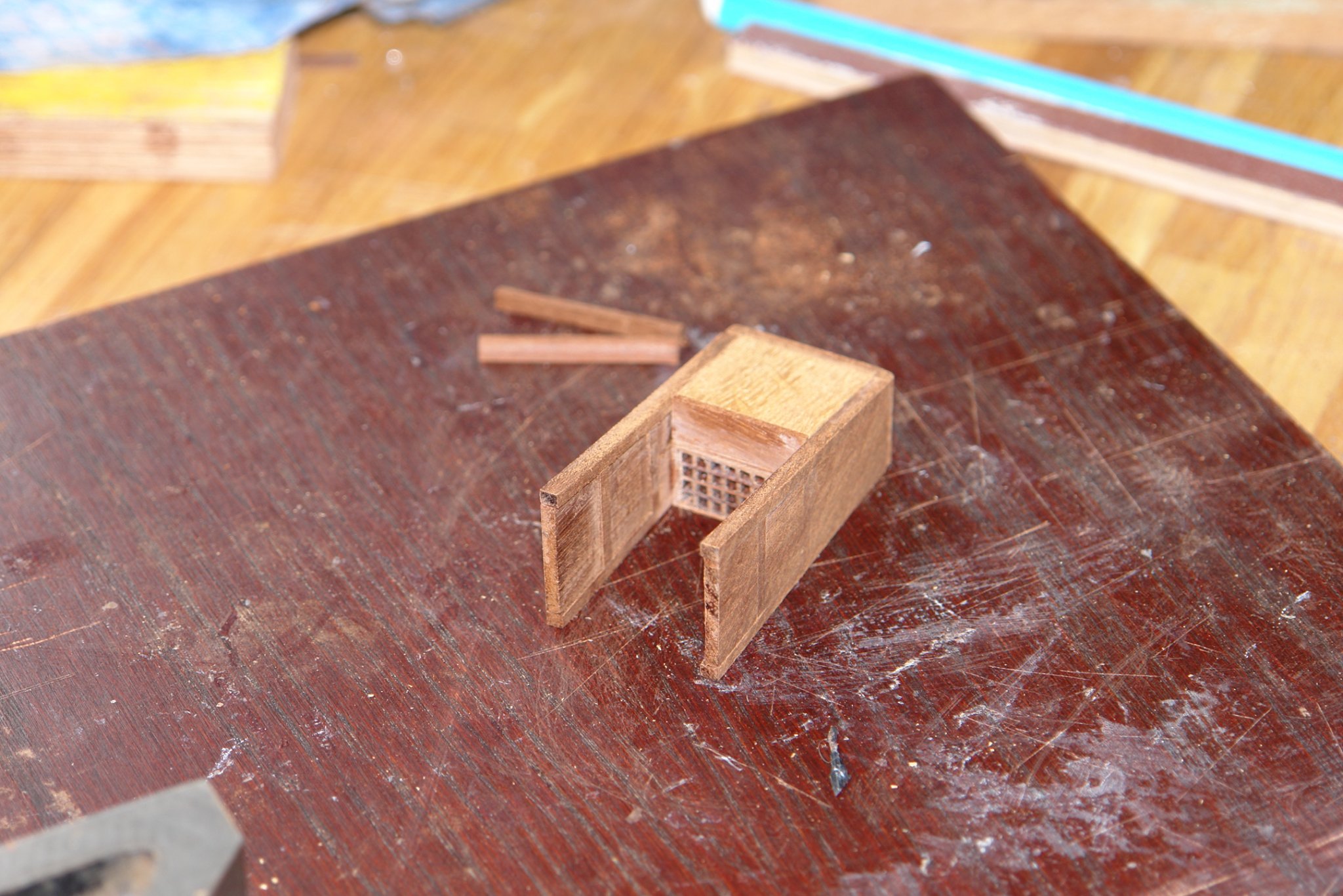
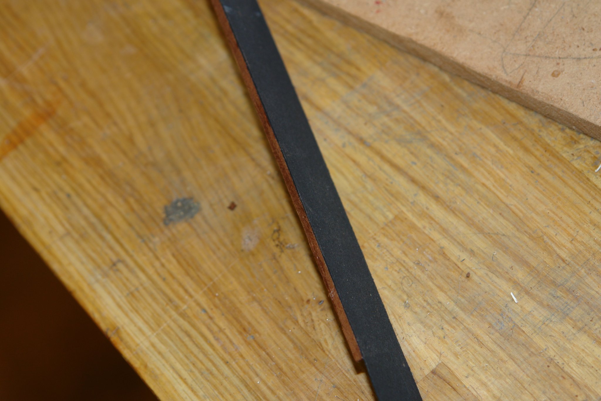
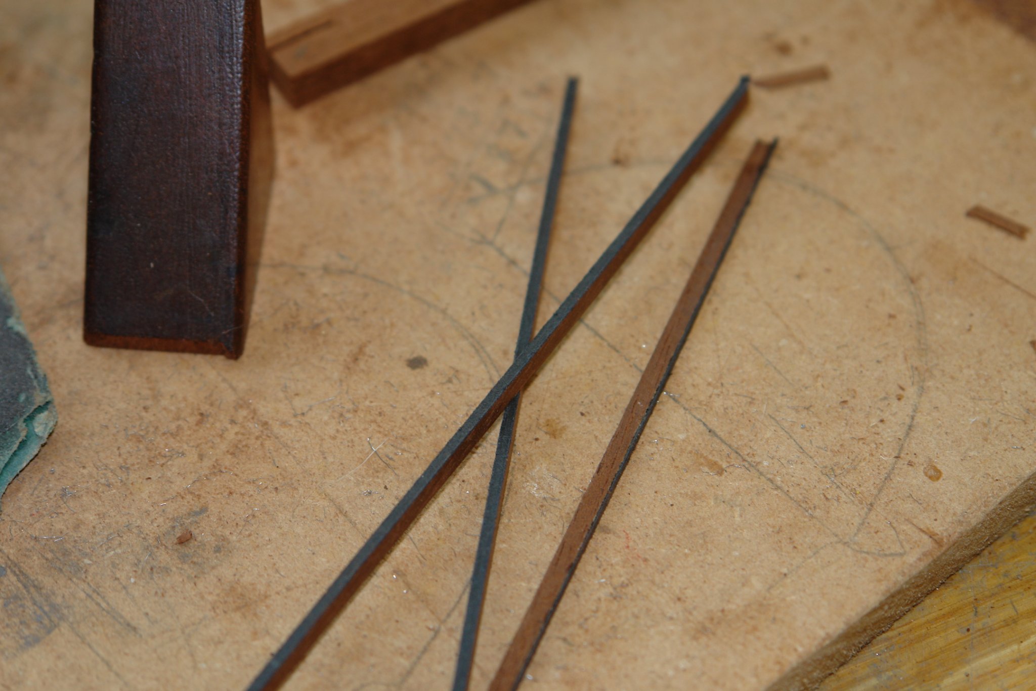
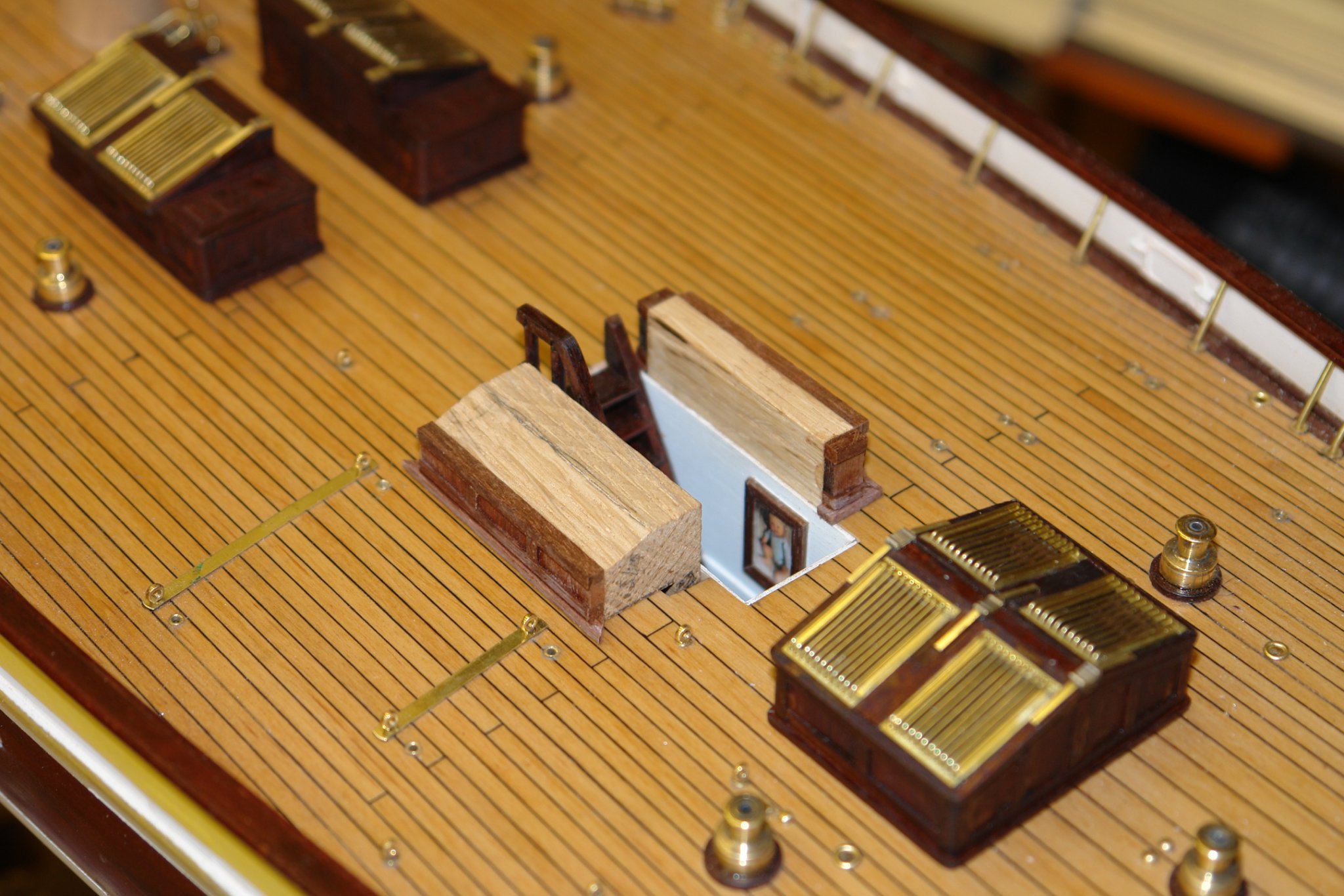
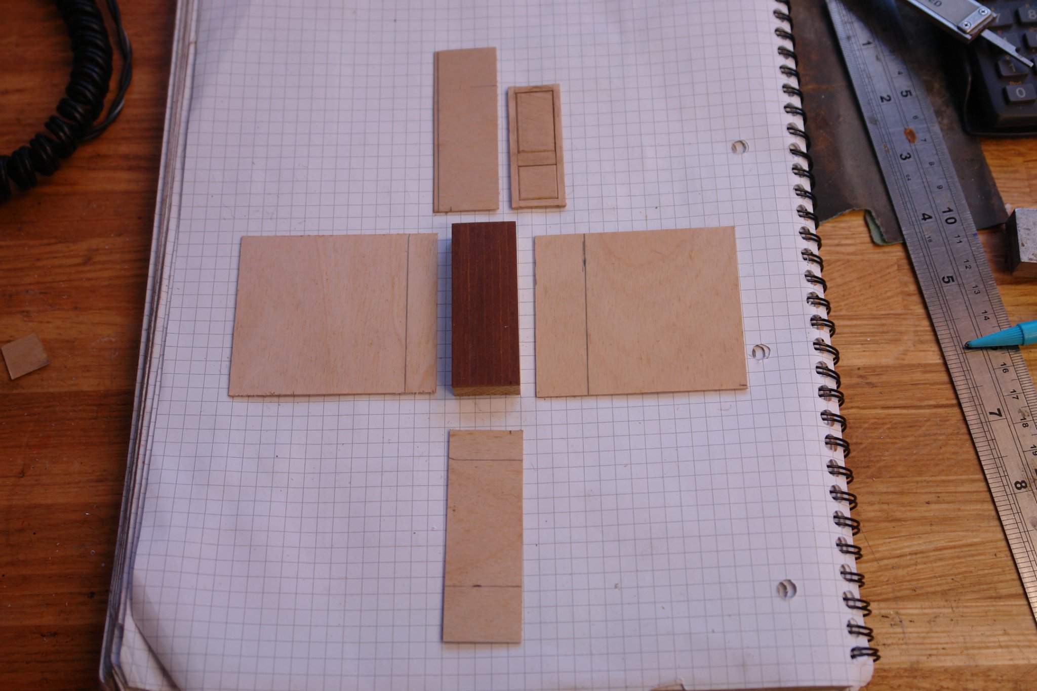
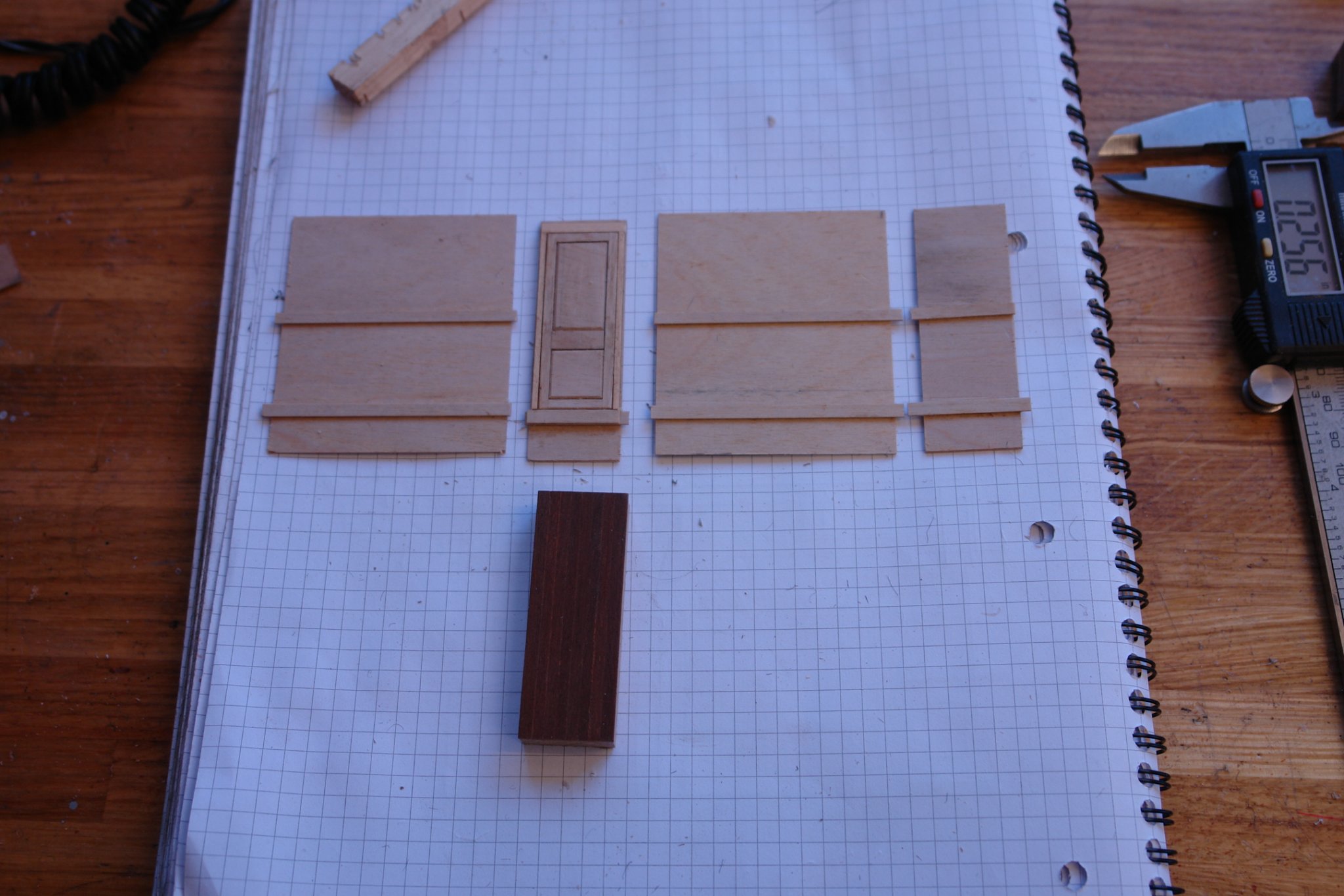
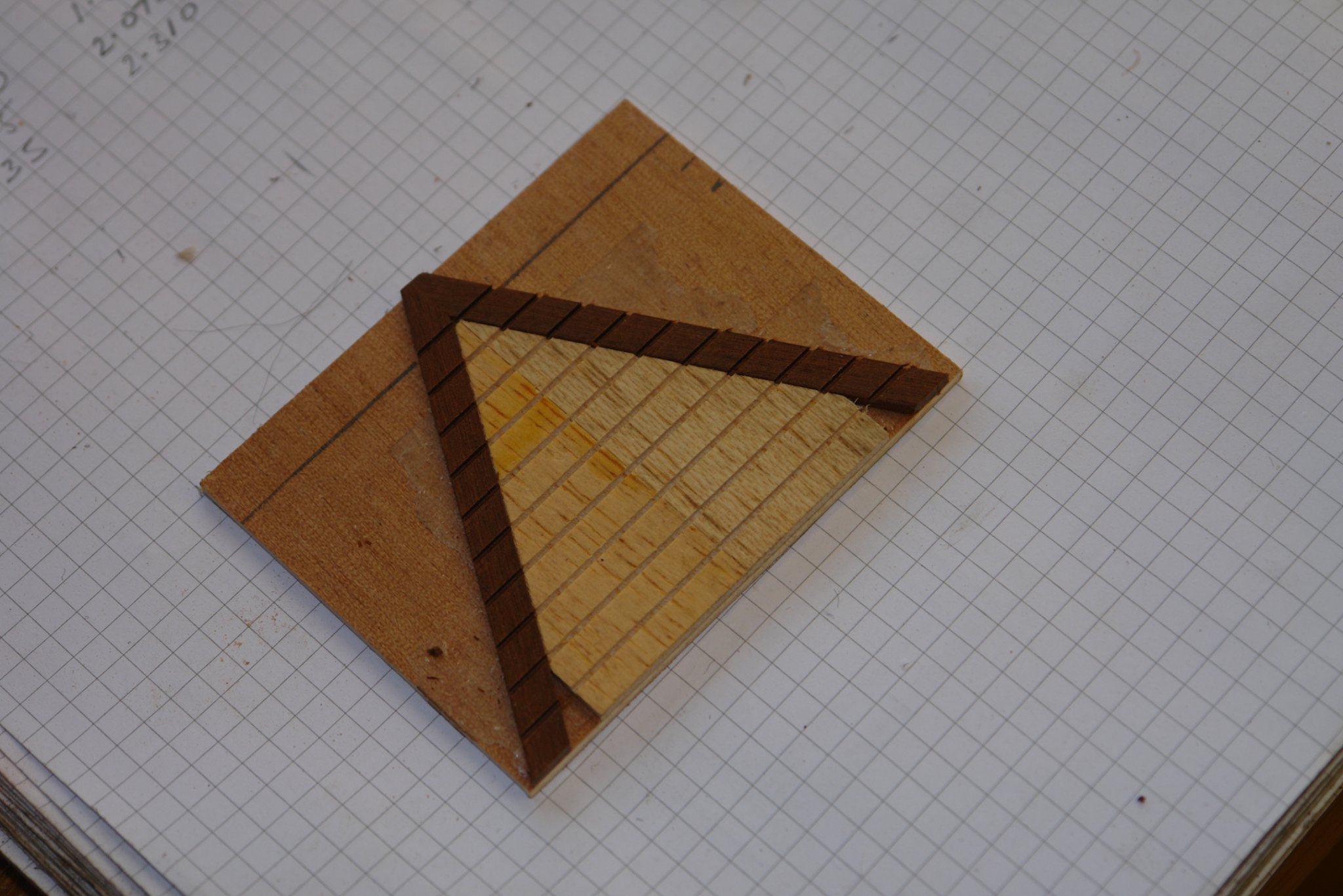
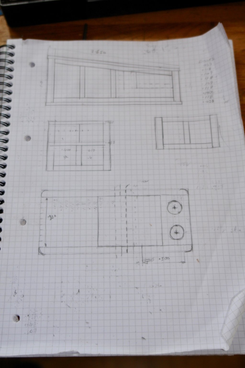
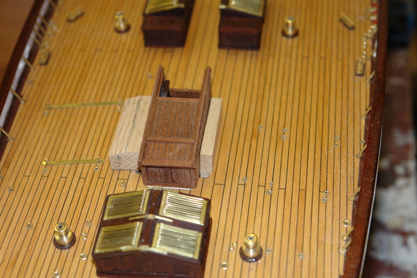
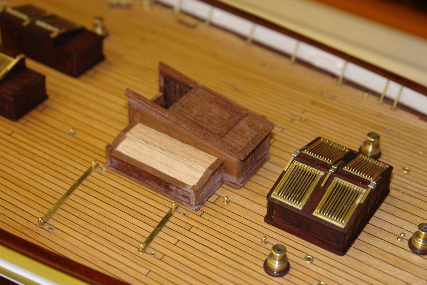
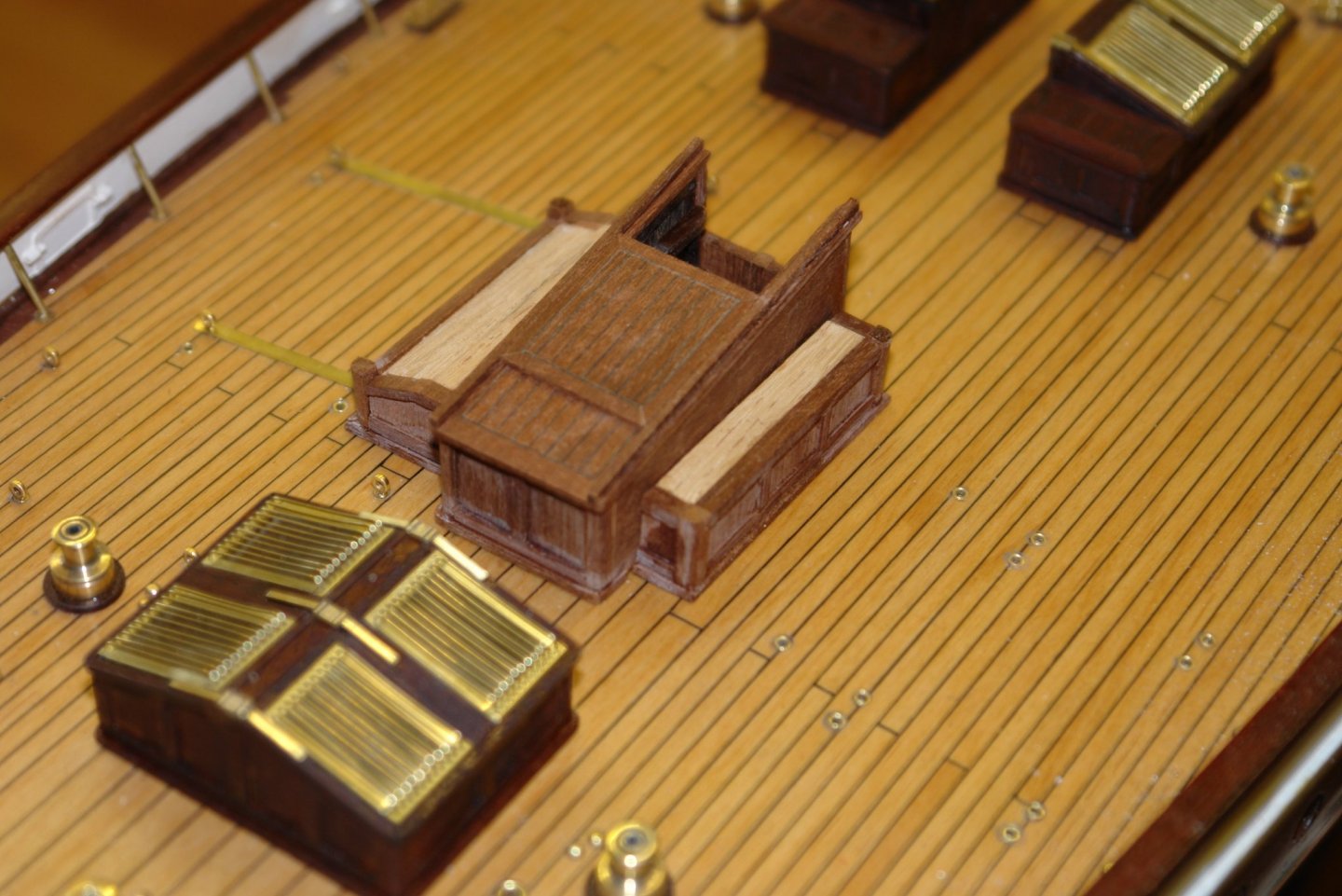
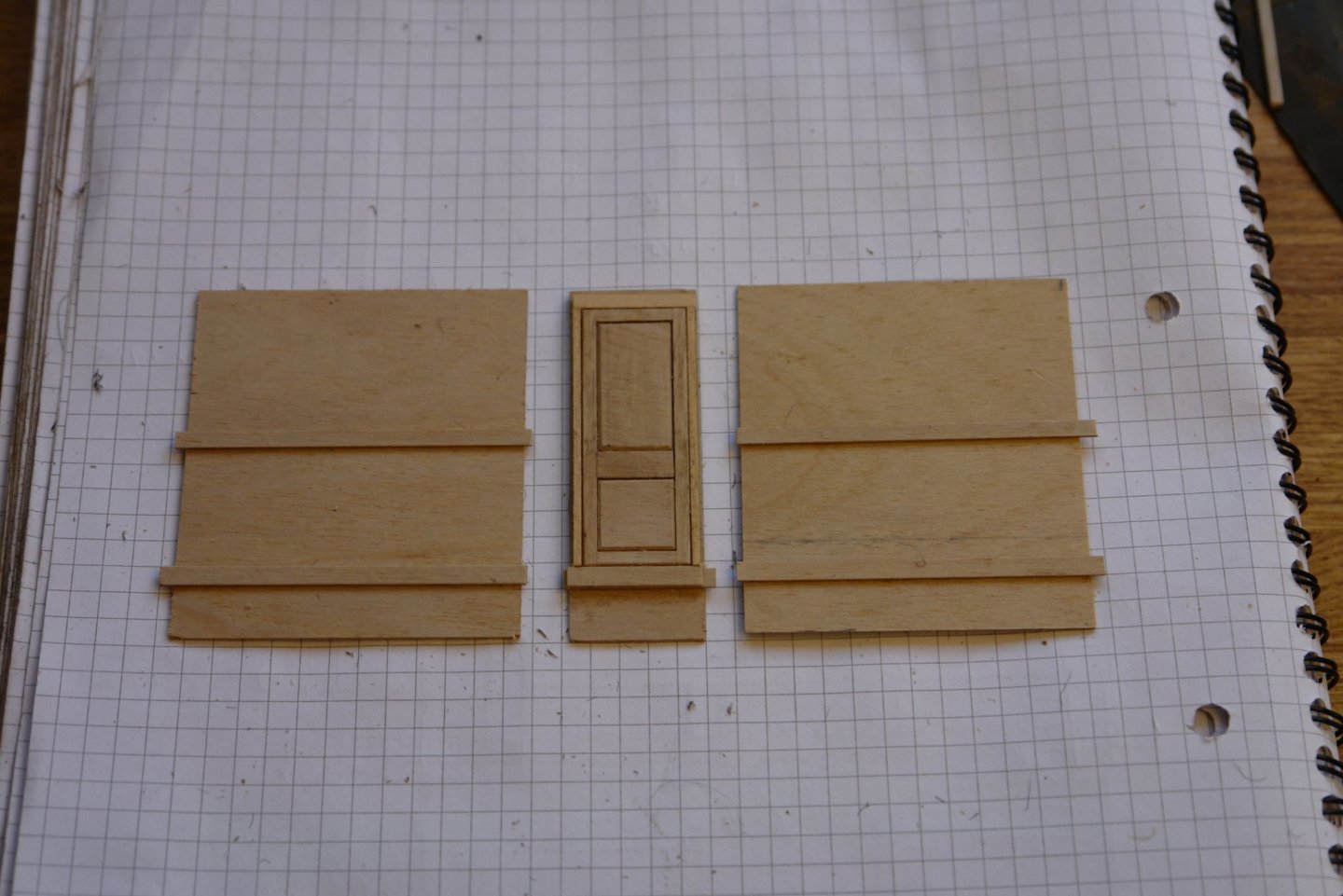
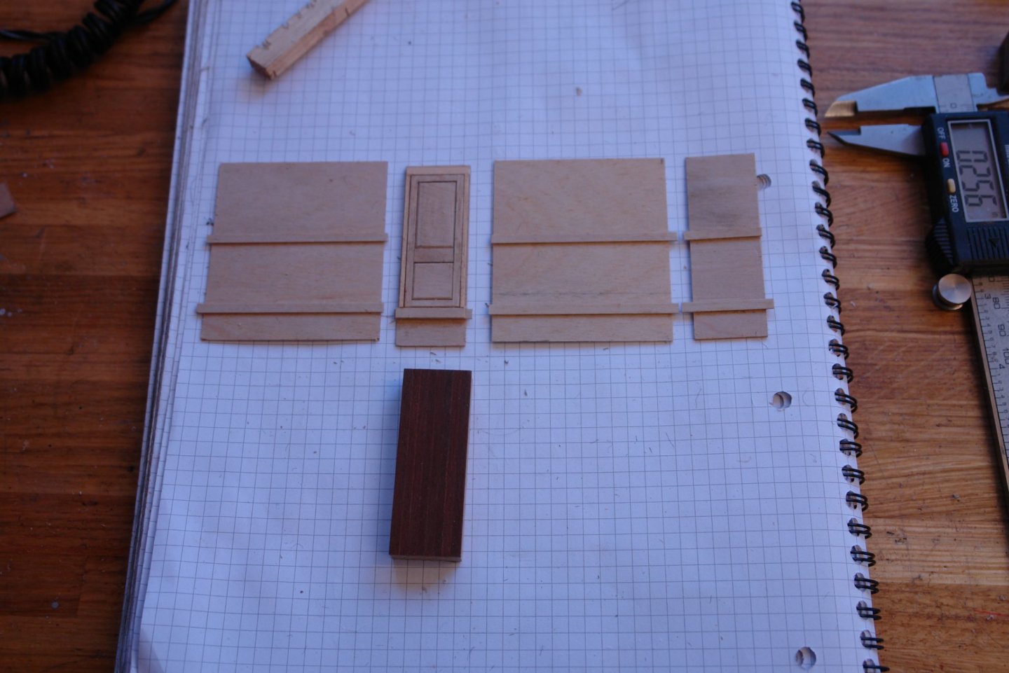
Over the last few days I have been progressing the deckhouse that sits above the stairway. In this instance I need to show some of the internal detail. The two side walls were built first before making the flag locker. The flag locker was a bit of a fiddle - the petitions being .025" wide and the pigeon holes being .075" square. A grid was cut in an oak block and the partitions built into this grid. This block was then used to join the two sides. I needed to create the top from mahogany planks separated by caulking. I can't remember whether I saw the following idea in another post or whether something I saw prompted this but I have to say it was very successful. Rather than cut the planks and then insert the caulking I glued the caulking card on to the pre cut stock before slitting off the strips I needed. The strip were 0.1" wide by .06" thick with the .006" thick caulking card. The result was very neatly caulked planking strips. The resulting top can be seen in the next photo. I then went on to make the wings of the deckhouse - this time by building them up on shaped oak cores. These were then clad with mahogany as previously. And that is it for the moment.


-
Magnificent work Kees - the hull looks spectacular.
- 193 replies
-
- 1
-

-
- wilhelmina vii
- fishing
- (and 1 more)
-
We all call her Splodge (or Splodgie) - her farther started it now all the family use it - mother, grandparents, aunts and uncles. I think it will stick.
-
You seem to be getting a lot of time in the shed Paul. I don't think I have ever used 3000 grit other than for polishing brass. You are clearly looking for perfection.
-
Being a schooner fan I am looking forward to see your build develop. Nice start.
-
Yes Keith - that is Splodge (she is named after her first ultrasound image). Eventually the yacht will be hers so a bit of personalisation seemed appropriate. Thank you Richard and Mark.
-
Quite a quick build Paul. It is what my wife would call high reward for effort. The bowsprit is really enormous isn't it.
-
I am always surprised to find kit parts of such poor quality, I know its driven by price and profits but can it really cost that much to turn out something that is passably ok. I remember kits of 30 years ago and I think that in the main the fittings were better - or maybe my memory is letting me down. Excellent alternatives Richard.
-
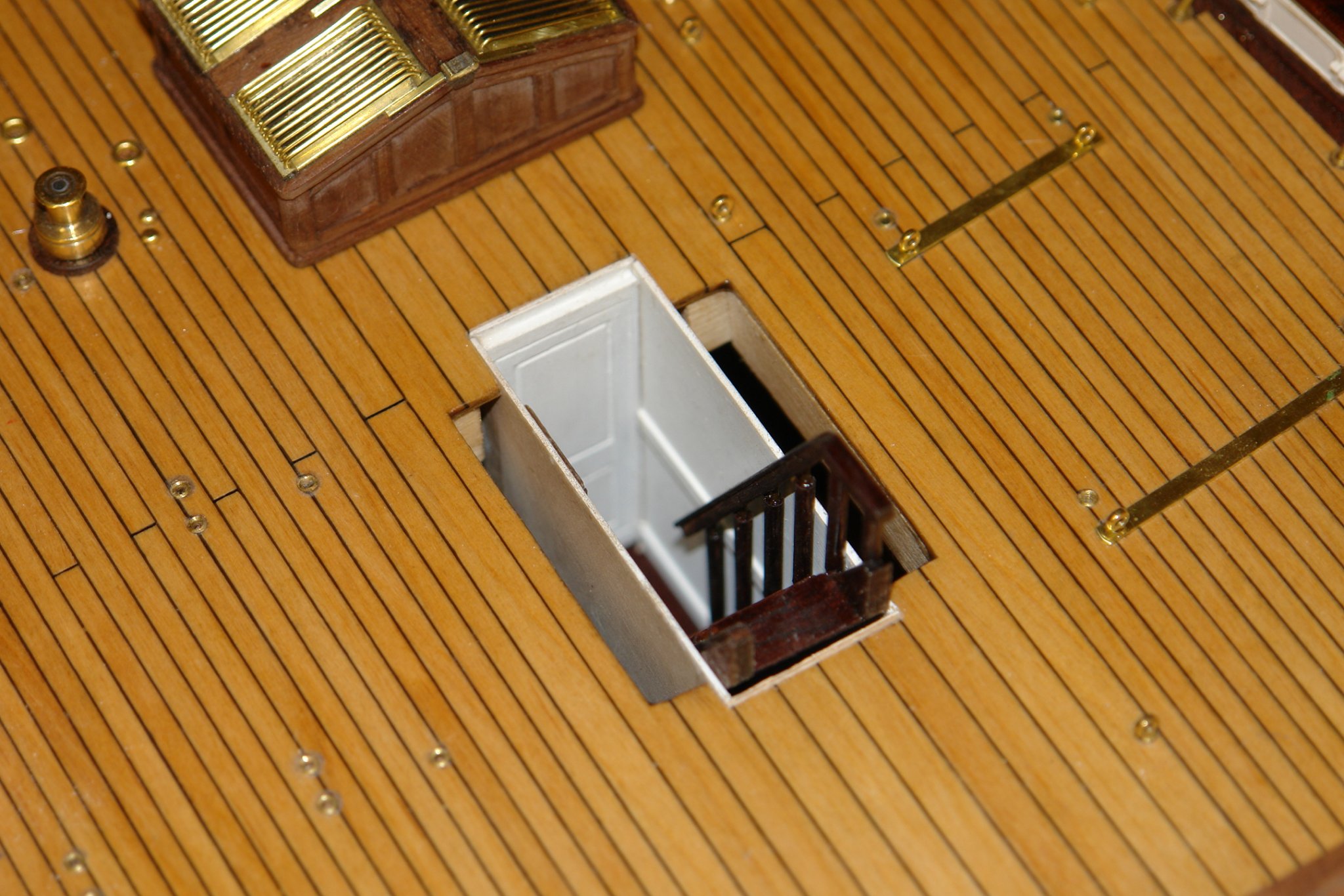
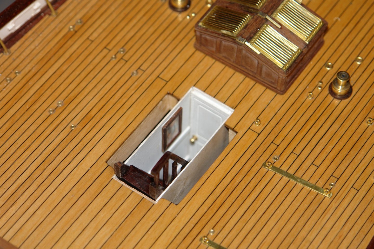
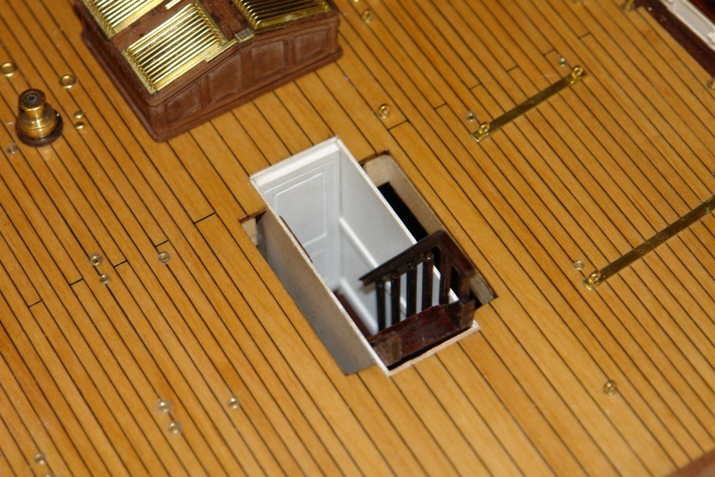
Eberhard you are quite correct - but in this instance the wall is the incorrect part. It's not terribly obvious from the photograph but I think there is a corridor on the starboard side of the stair. In any event very little of the interior will be visible through the hatch.
-
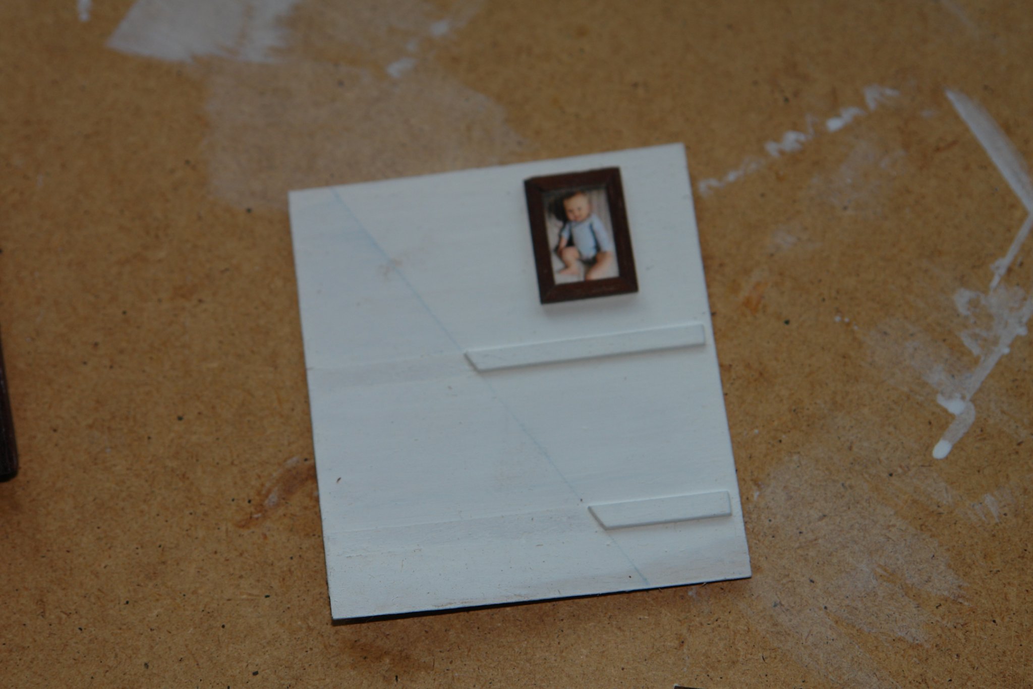
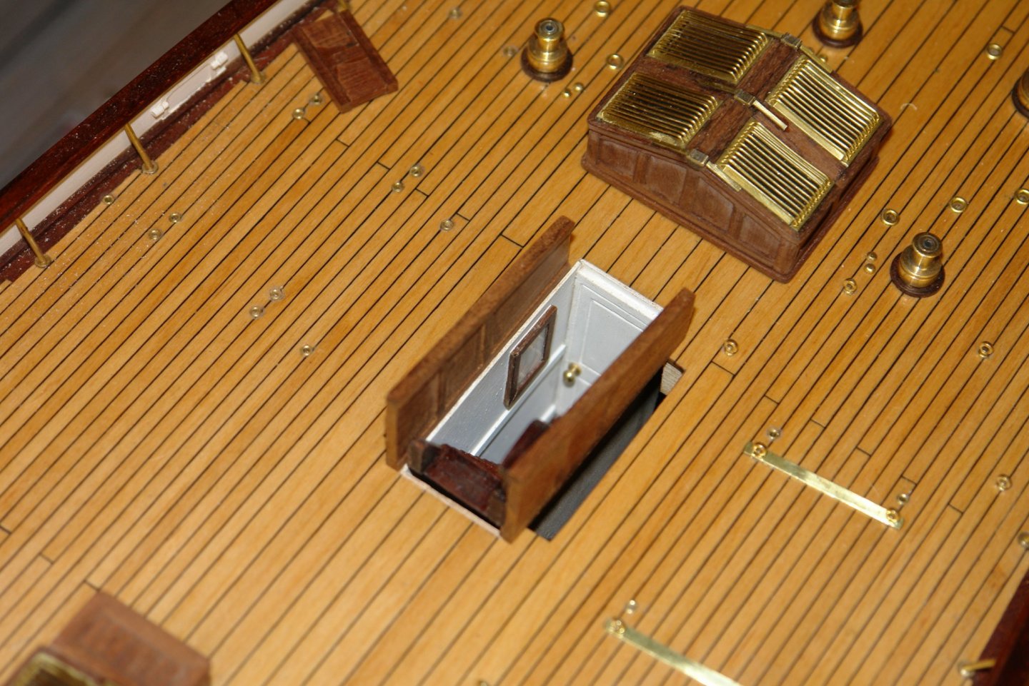
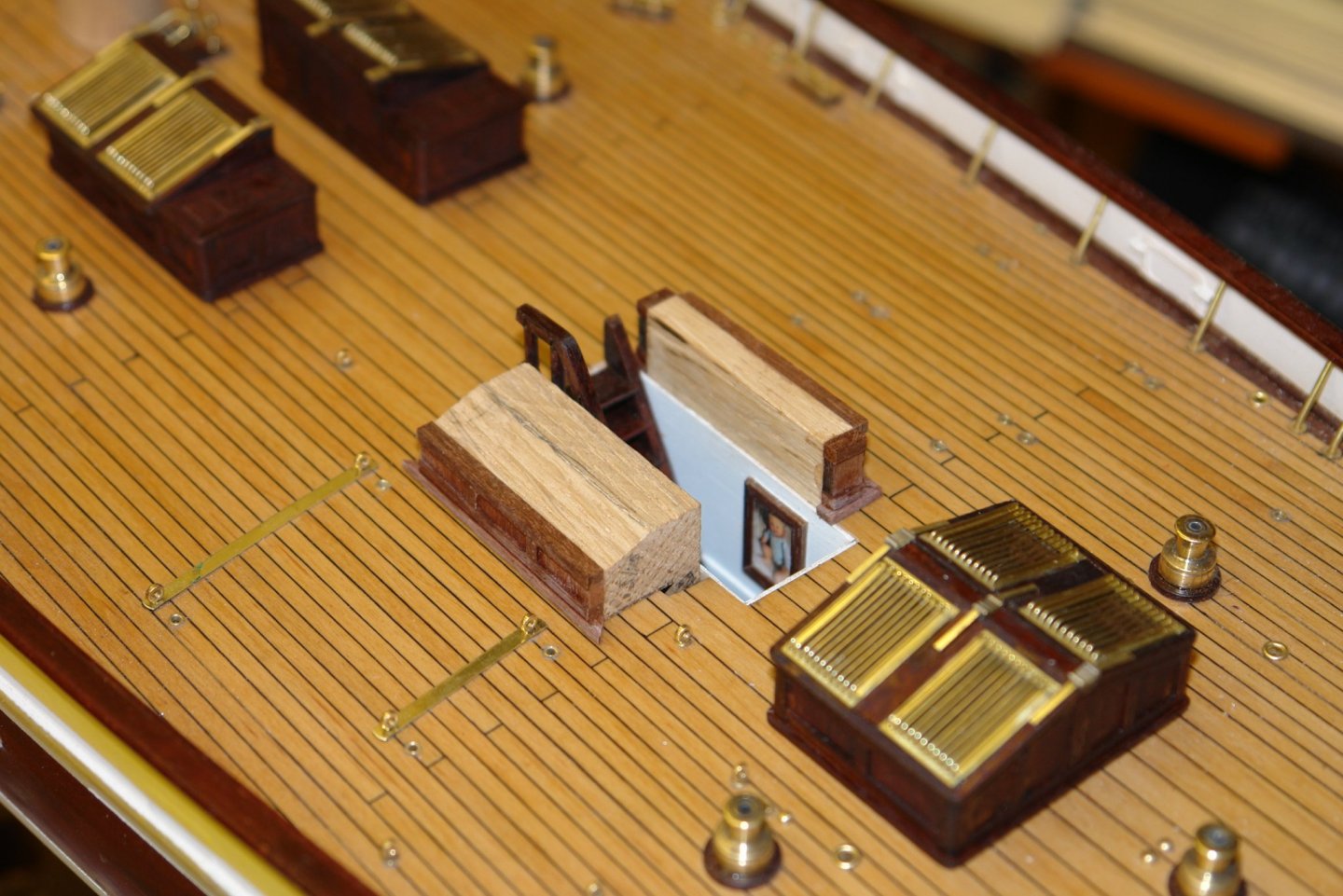
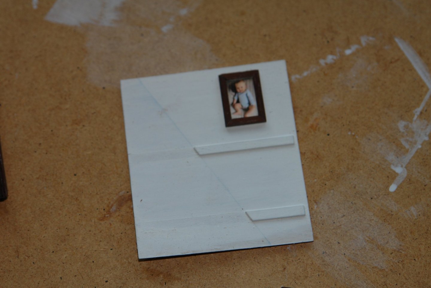
Paul, Pat, Richard, Boris and Mark - thank you all for your appreciative comments, they are most welcome. Also thanks to everyone who visited or liked my work. A bit more progress:- I painted the interior walls but felt they needed a picture. The walls were then assembled around the floor piece. The door got a brass knob. The completed interior was then inserted into the hull.

-
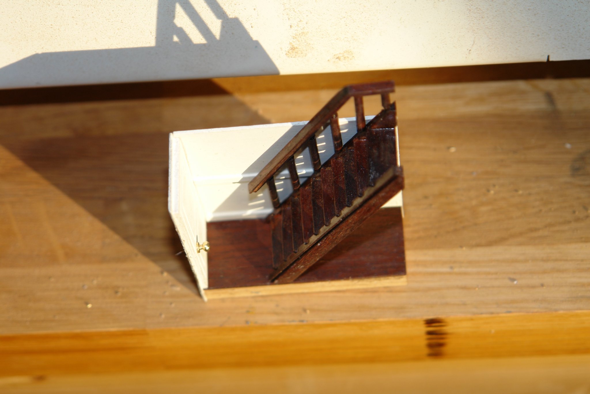
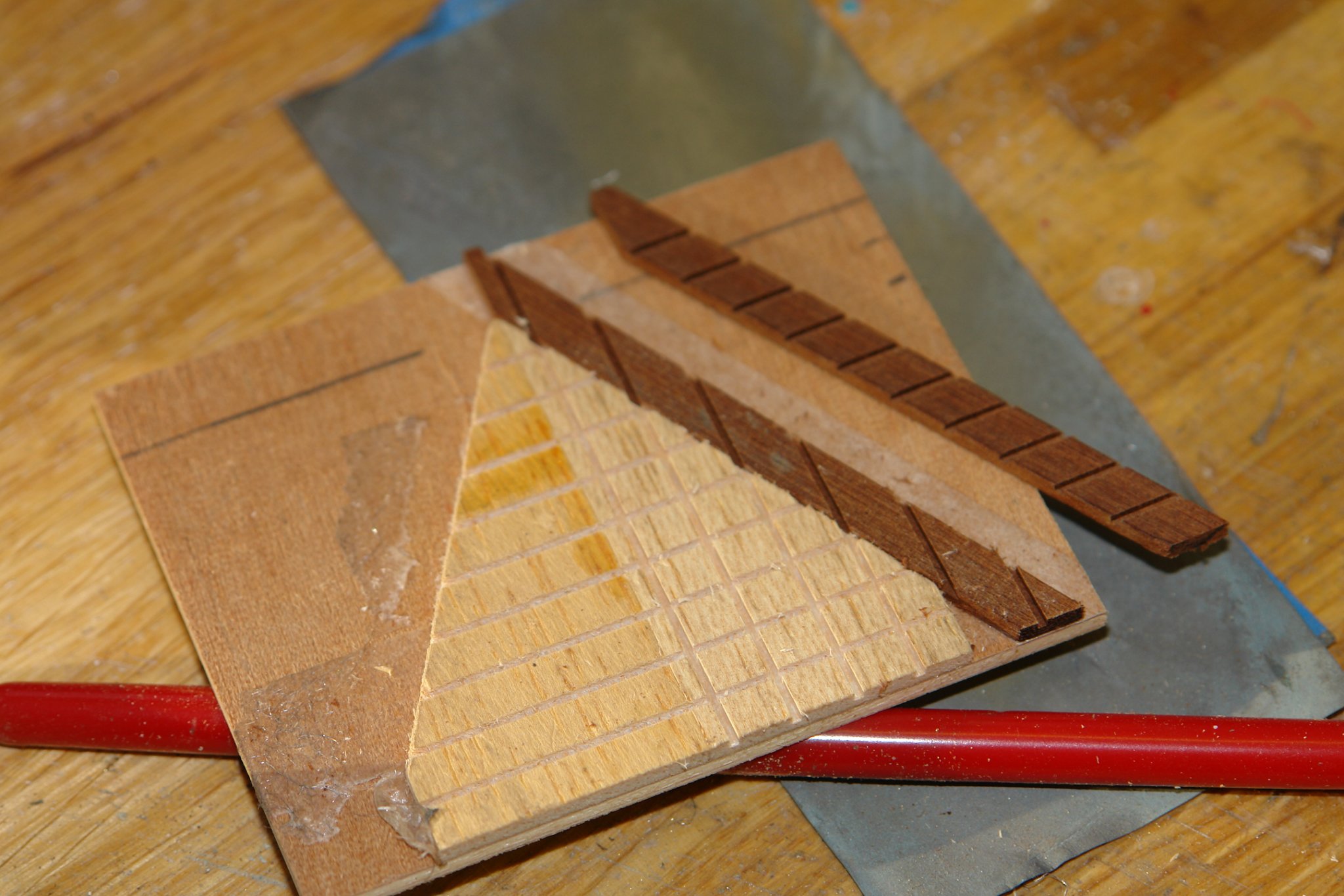
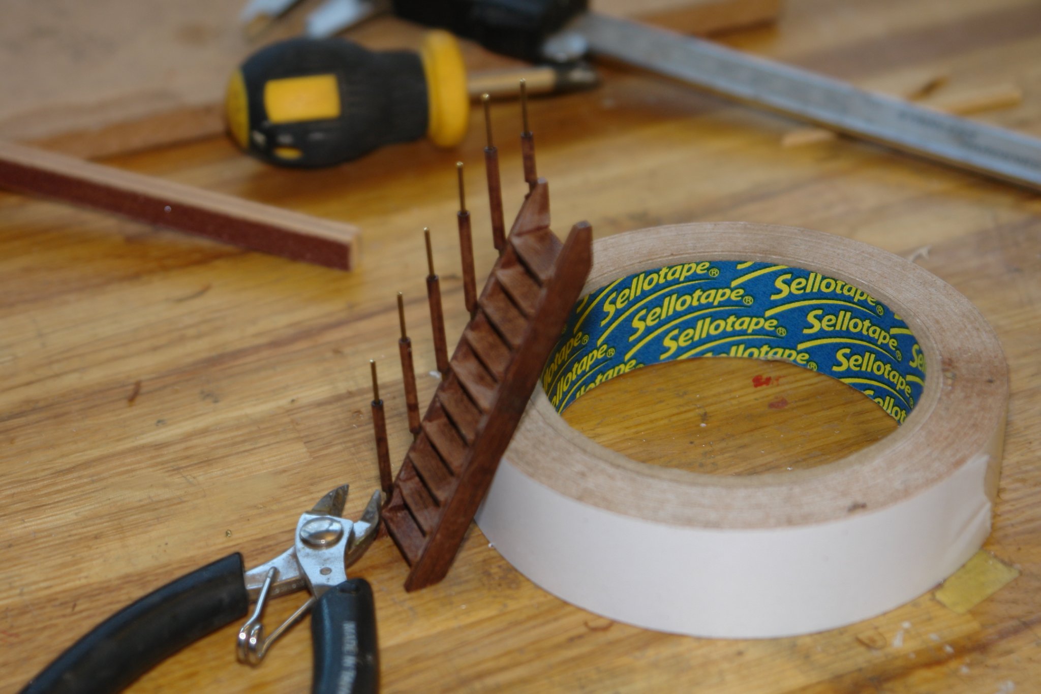
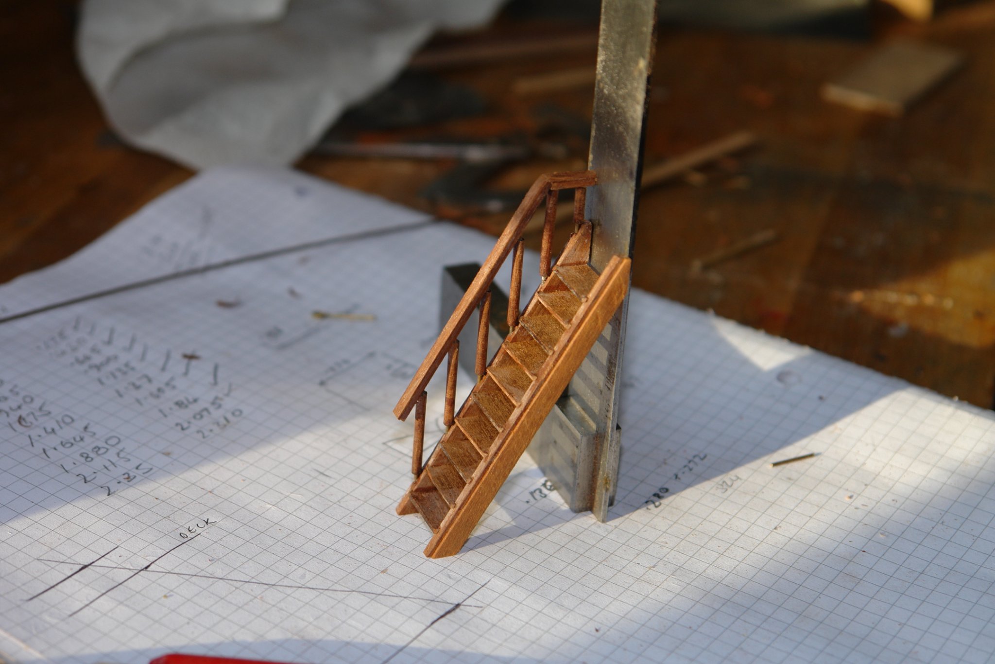
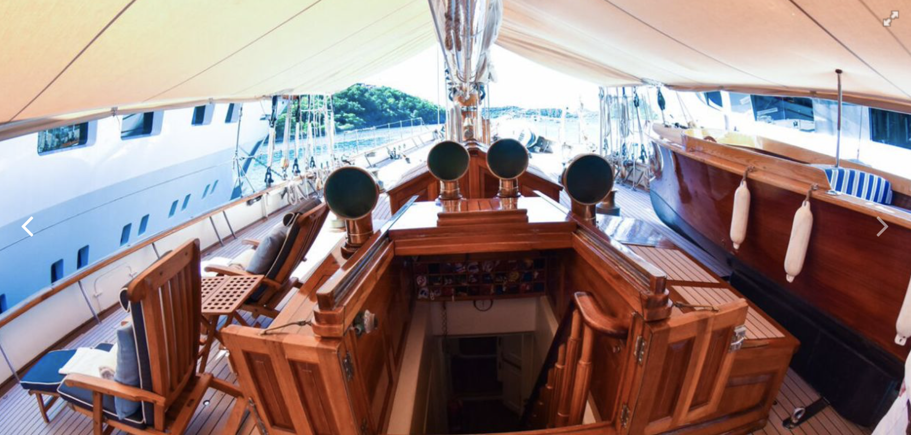
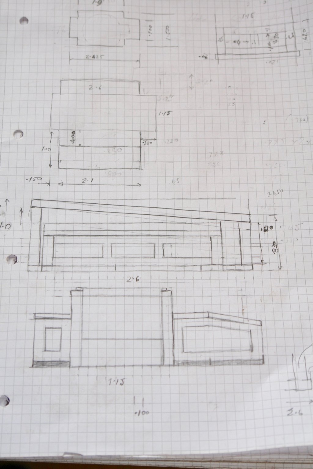
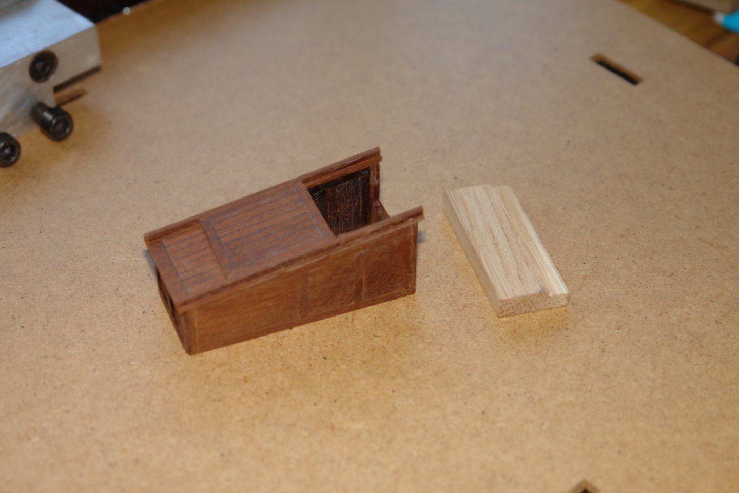
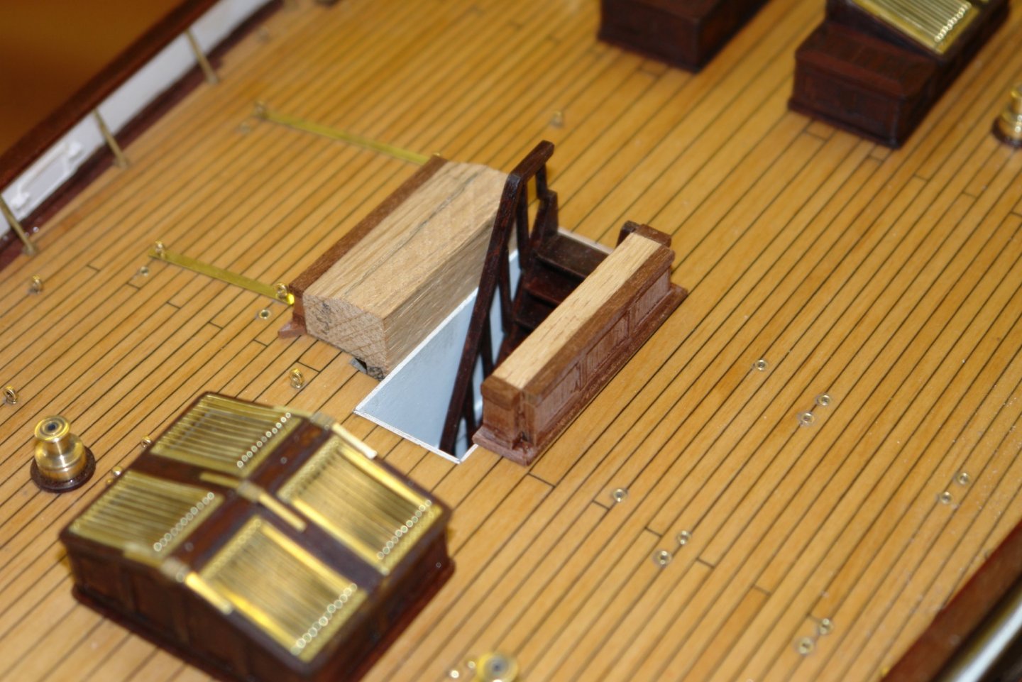
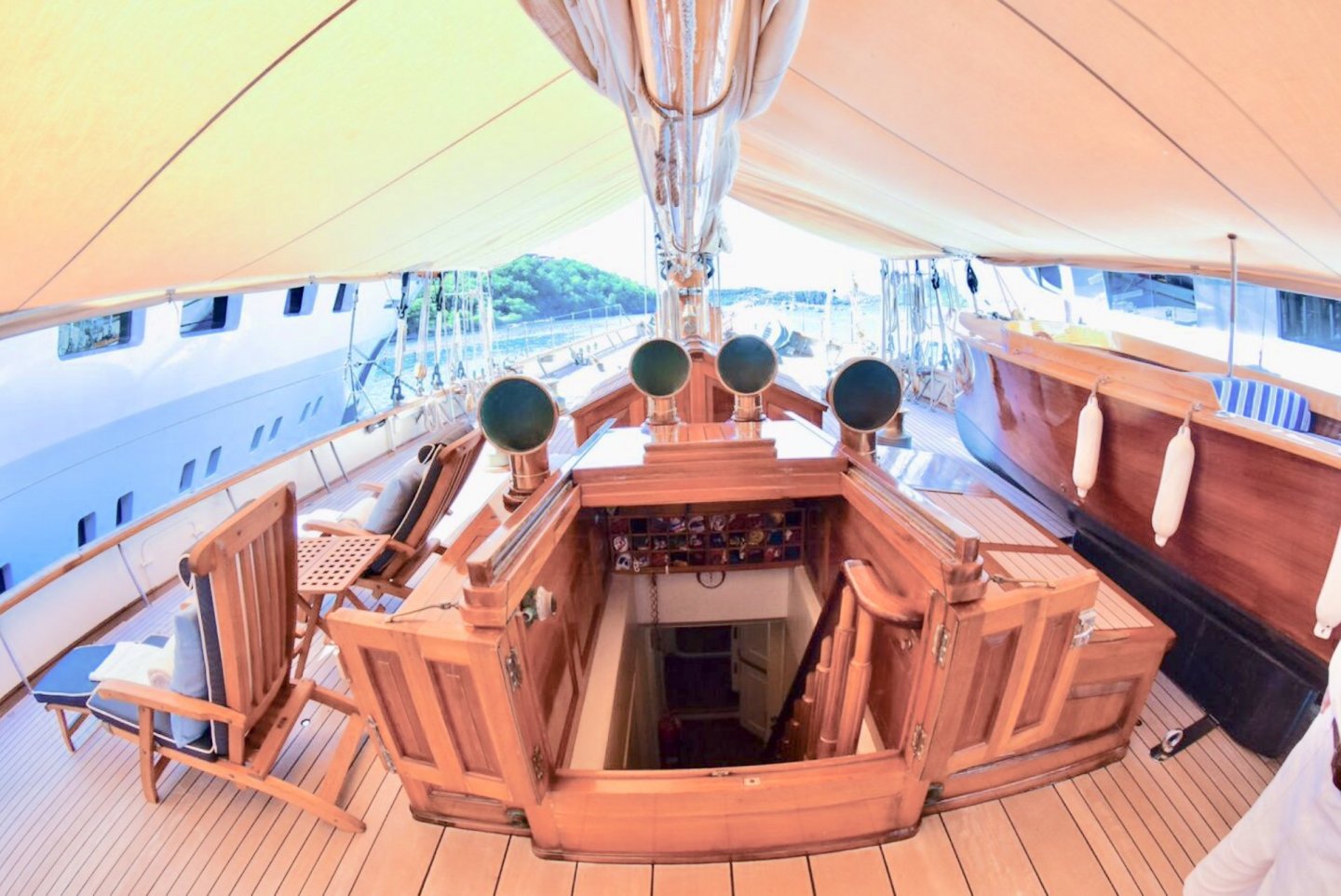
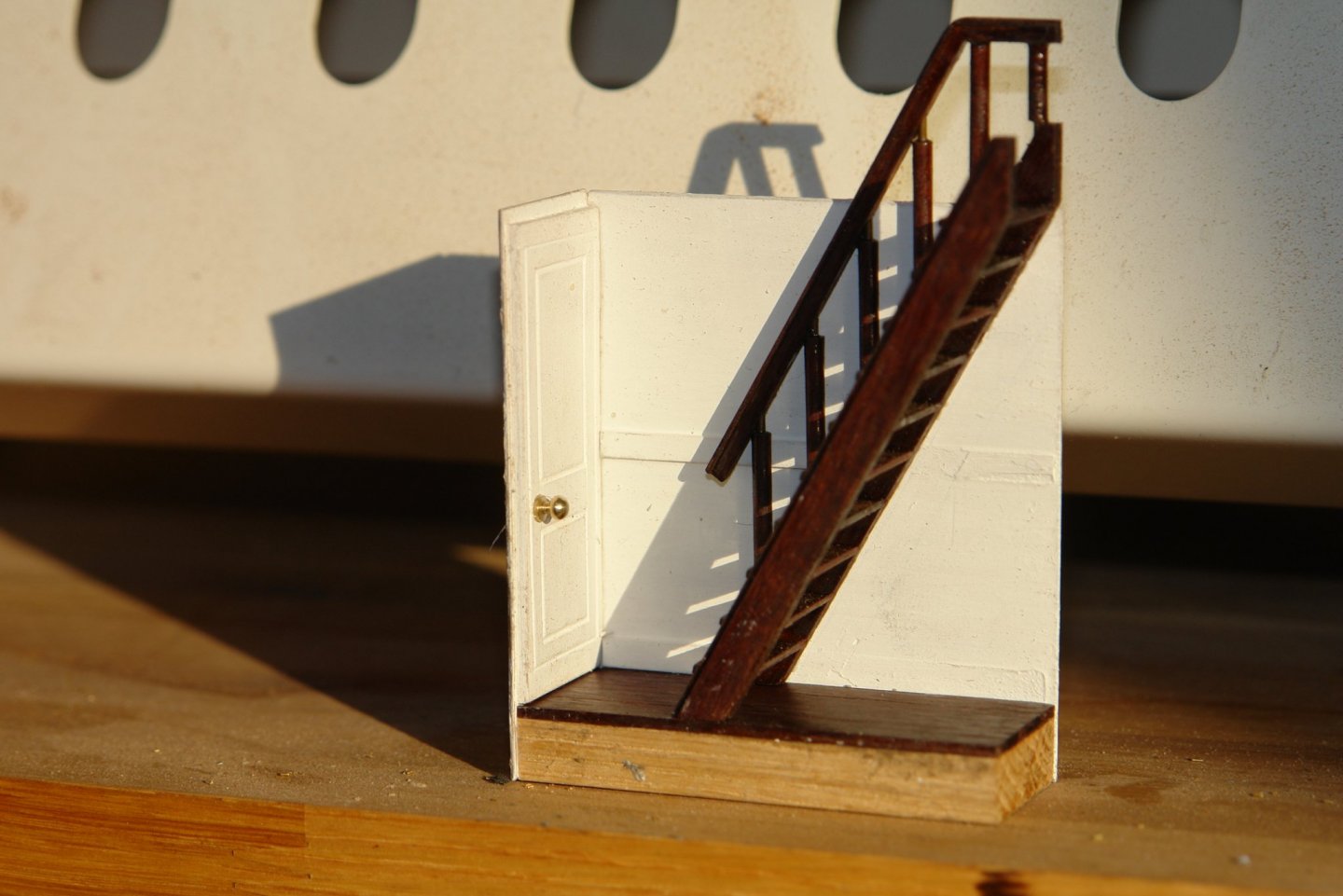
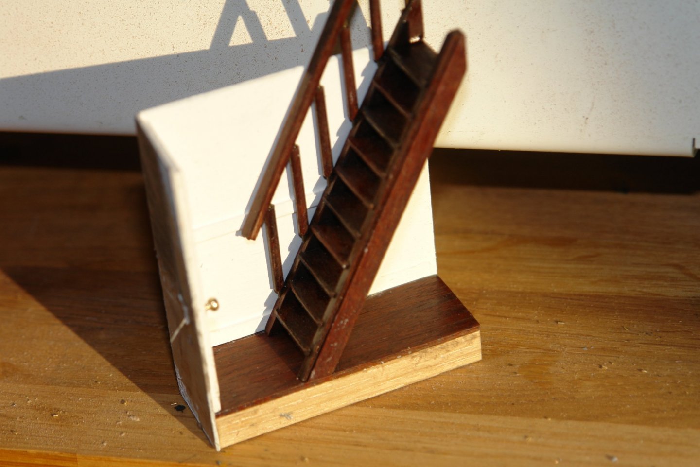
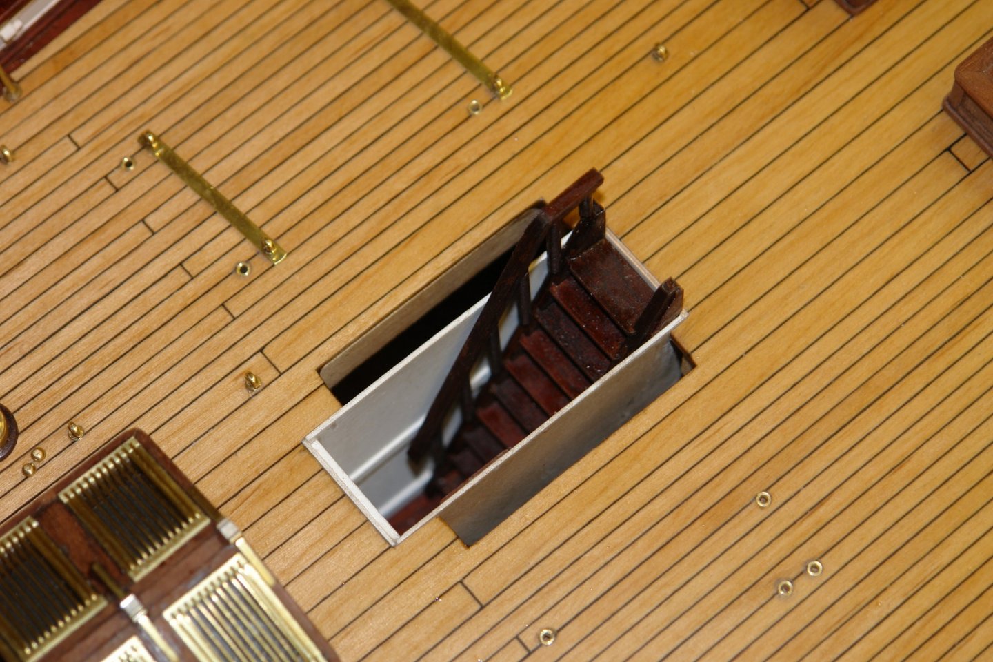
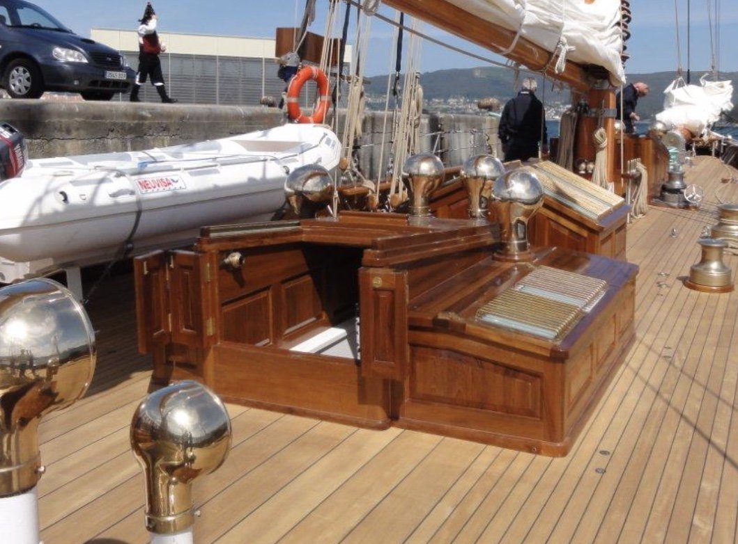
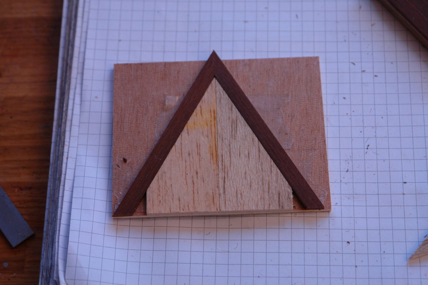
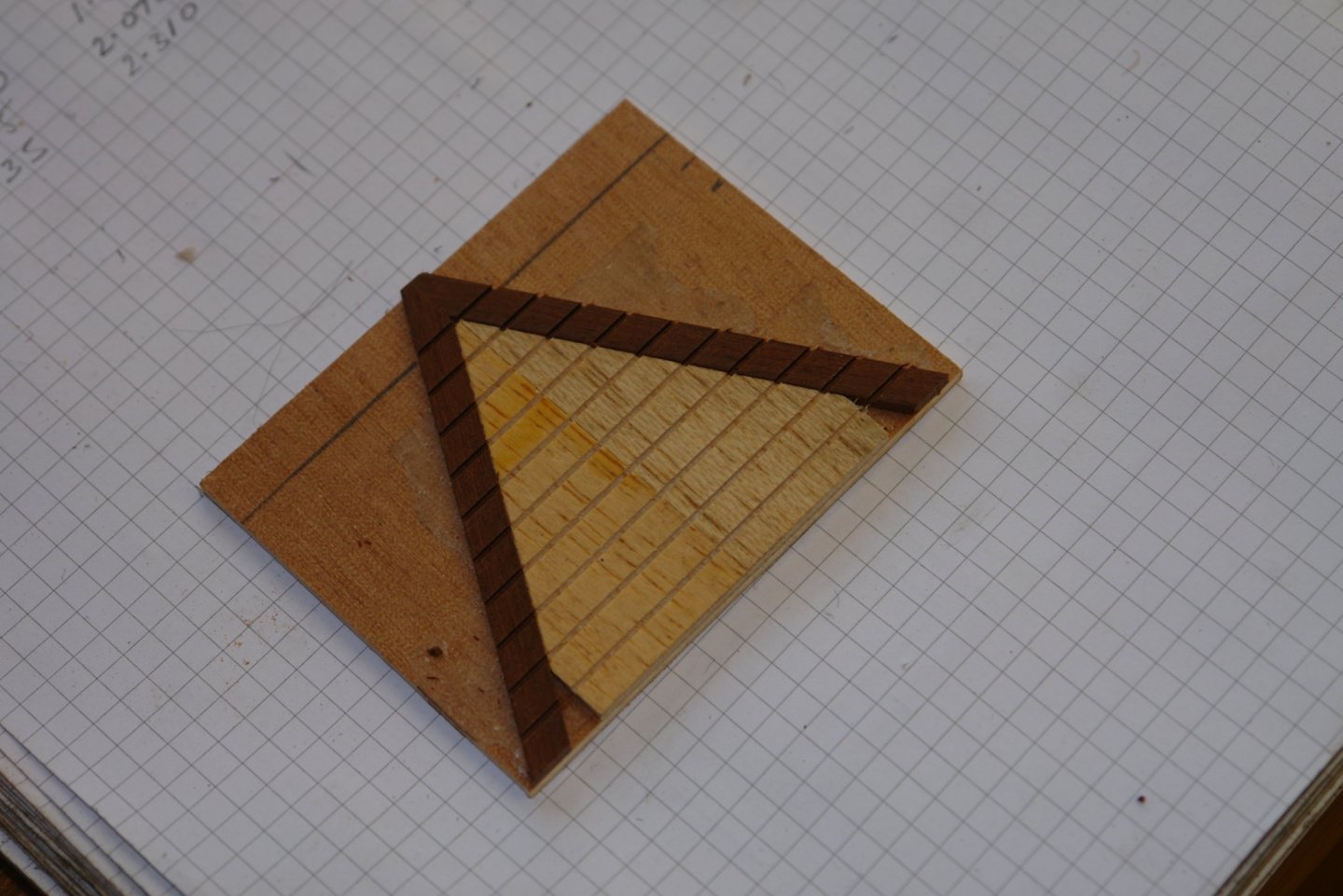
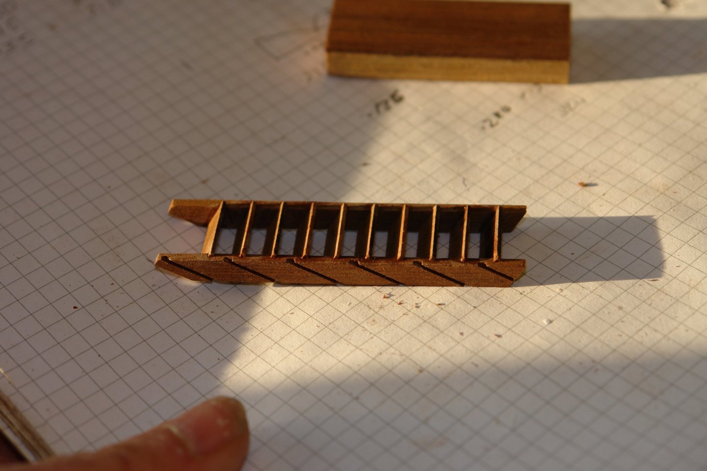
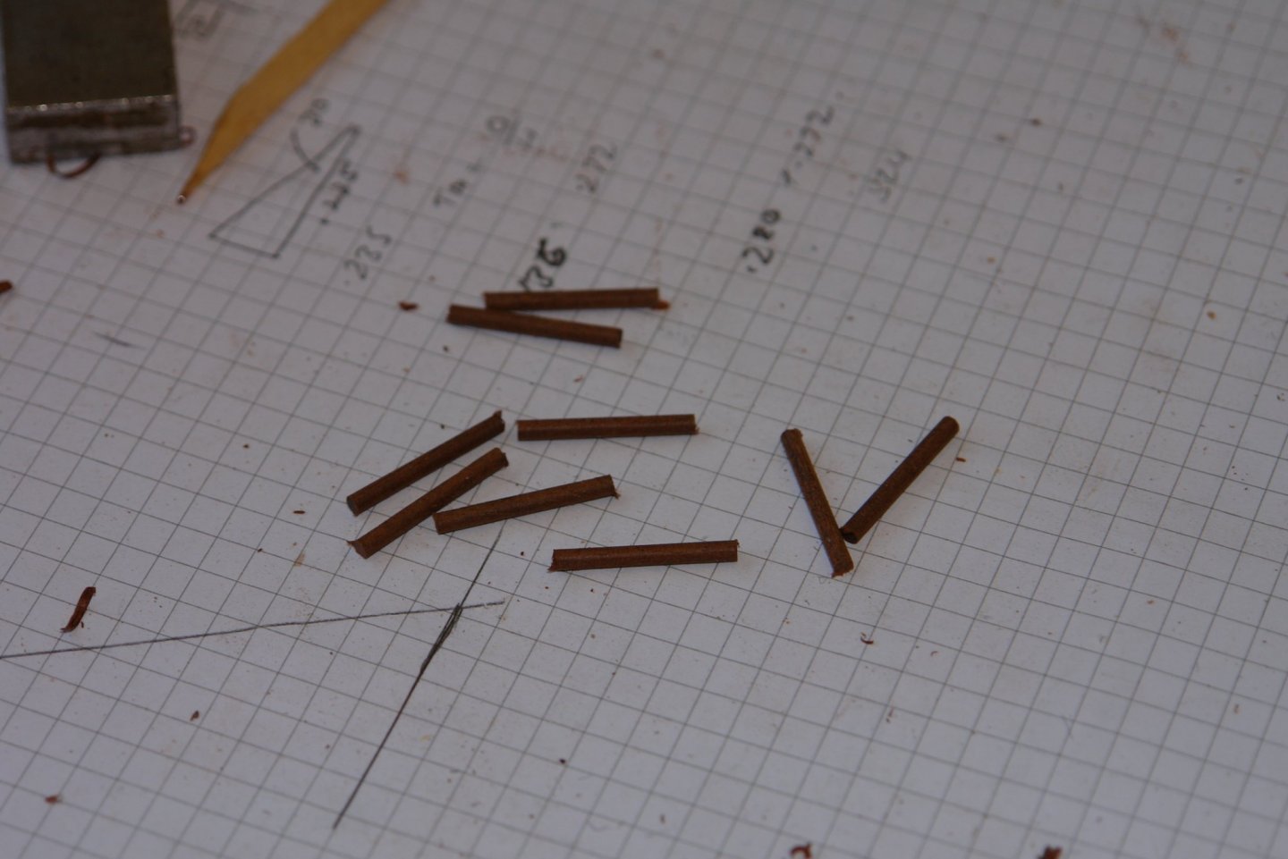
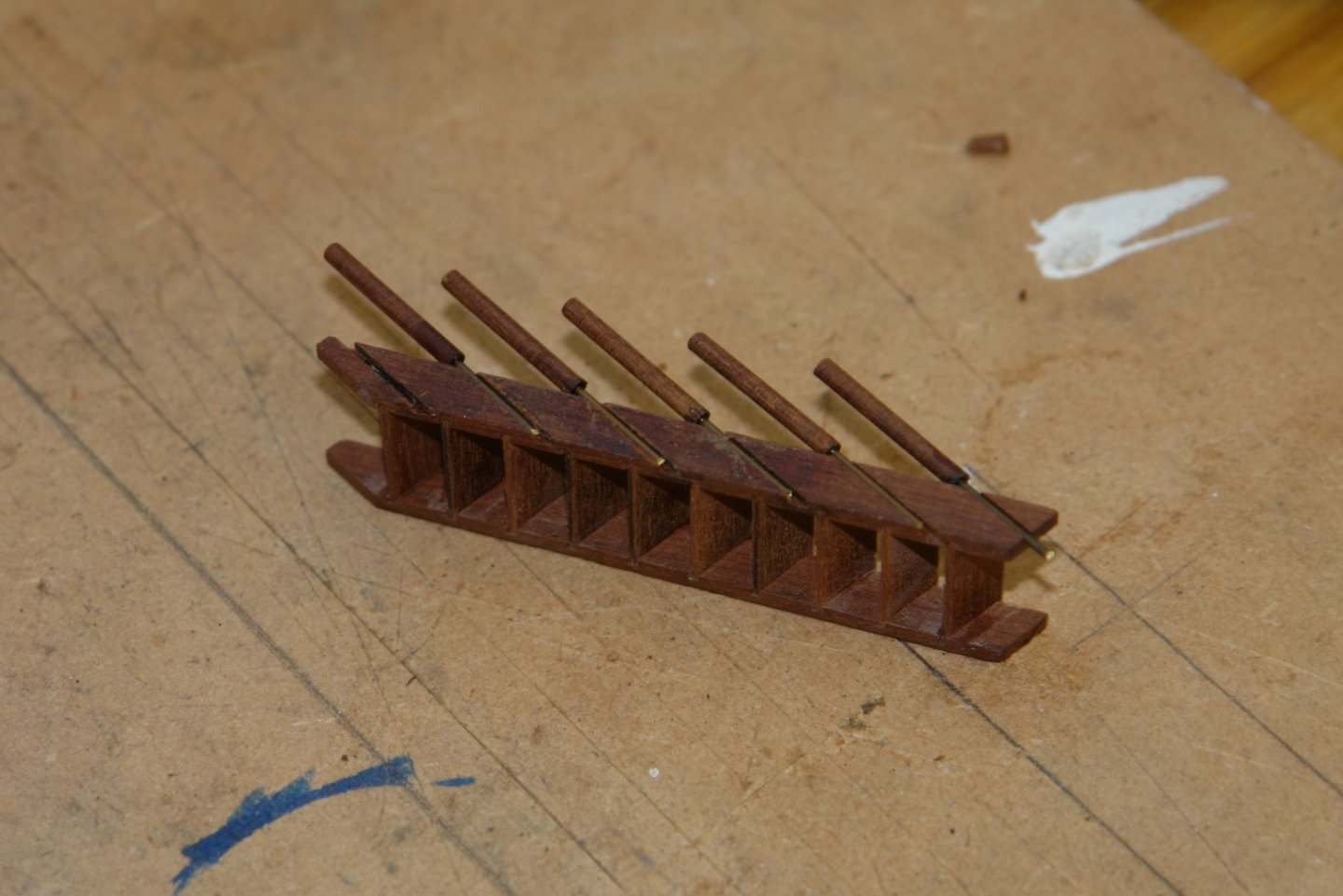
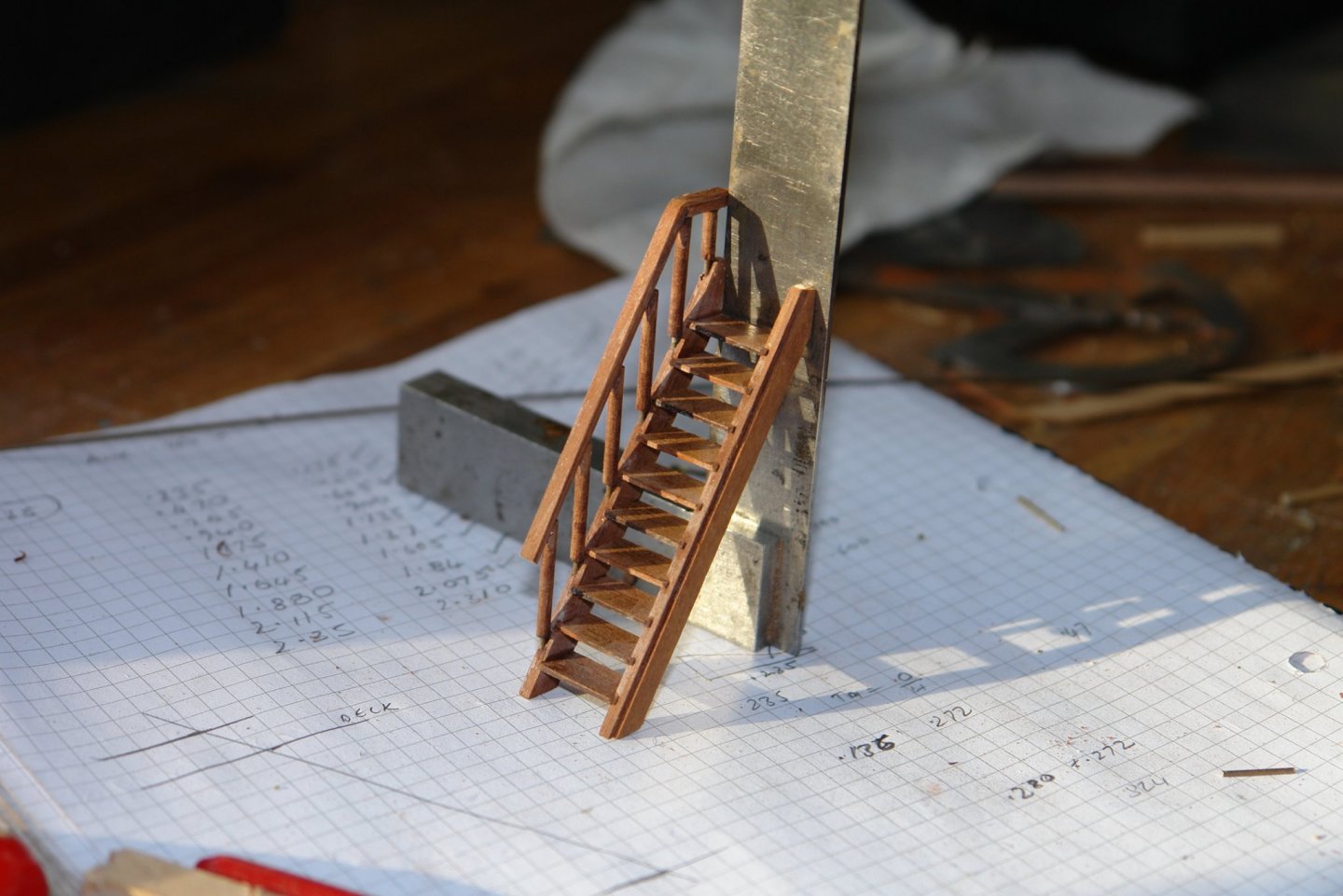
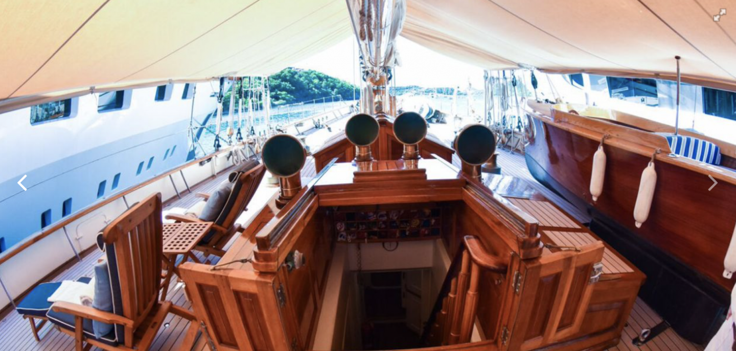
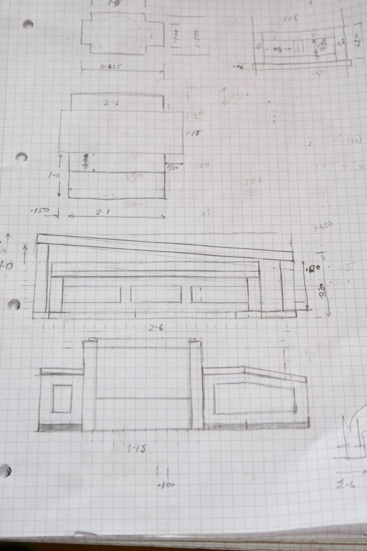
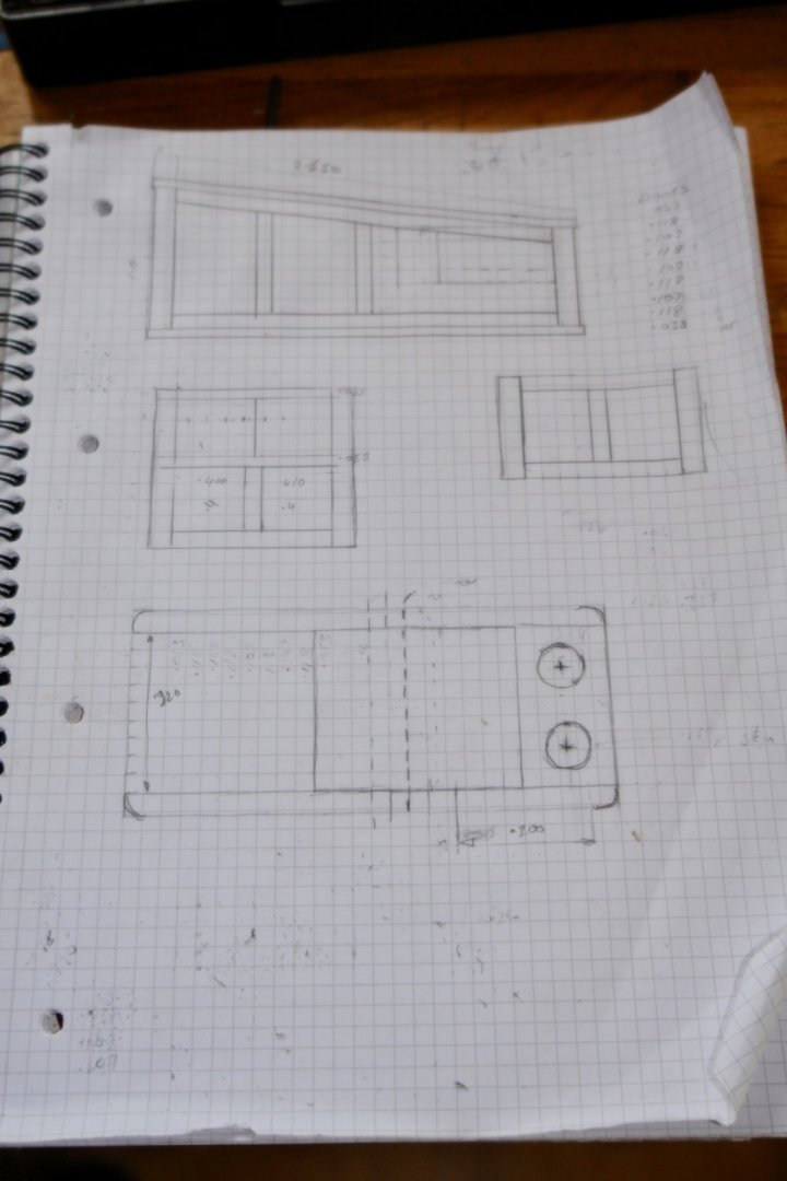
I am still on deck houses but this one is a little different as the hatch / doors will be open giving a glimpse of the interior. As usual I started with a sketch, again one square represent 0.1" x 0.1" at model scale. This deckhouse is asymmetric and as before I will build the skylight version. I don't have much detail of the interior but I will build what I think I see through the hatch. A little bit of photo editing gives more detail than is apparent on the photo. I started by building the interior which consists of a floor, door and 4 walls. The walls have a skirting board and a dado rail. The walls and the door are made from 1/32" ply. I constructed the stairway sides on a template that facilitated cutting identical slots for the steps. Using the same template I also cut slots to take the stair spindles. The steps were cut and the stairs were assembled and glued. They are just over 2" long The spindles were .08" diameter and were made by drawing mahogany through a draw plate - they were then drilled and wire was inserted in each end to fix them in the pre-cut slots in the step sides. The handrail was then shaped and attached.


-
Rob Get a piece of aluminium rod bigger than 22mm. Turn the outside diameter down to 22mm - buy the blade first and then you can make sure it fits. Drill a shallow hole for the bore and then open it out to O.5" - use the plate from the saw to check that it fits over the small spigot. Then part off the spacer to the width that you want - i.e a couple of thou thinner then the thinest blade you want to use. If turns out a bit thicker than you intended thin it off by rubbing on some emery paper. You could use steel but parting off might be difficult unless you have a larger lathe, brass is also an option but more expensive.
-
Very nice between deck shots Paul, looking very realistic.
-
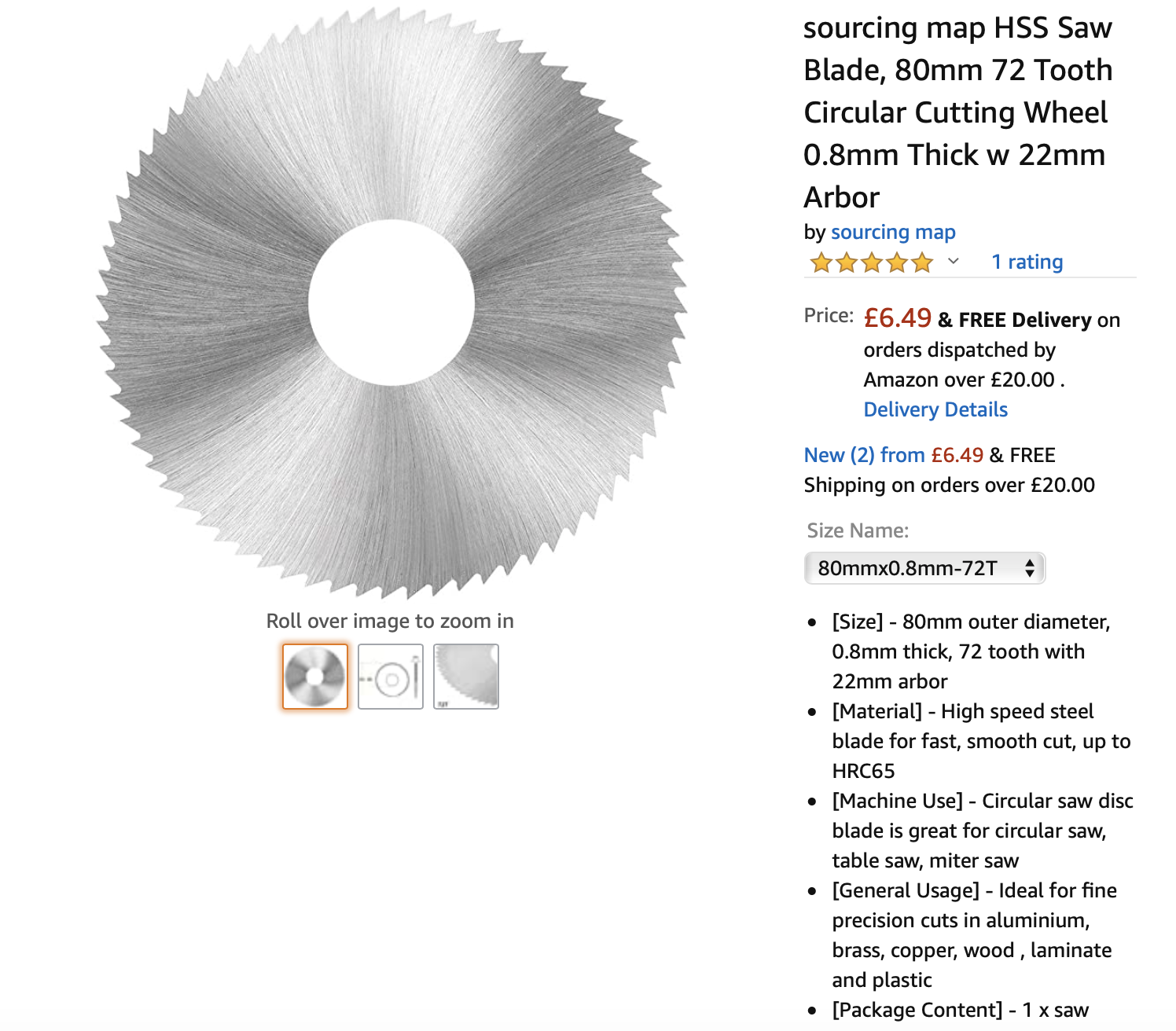
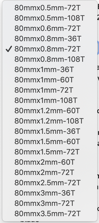
Rob - I buy TCT blades from Byrnes - i have not found another good source. For slitting saws I use these from Amazon. As you can see they come in a range of sizes. I don't use less than 0.8mm for slitting planks as anything less tends to deflect and hence bind. I do use down to 0.6mm thickness for cross cutting on thin and narrow wood. I have a lathe so made up the spacer to convert from the standard 0.5" spindle to the 22mm bore of these blades. Jim Byrnes supplies spacers at a relatively modest cost but I don't know about shipping cost. Alternatively I can make you one.

-
Very educational insight into this unusual vessel and a lot of fine detail.
- 81 replies
-
- 3
-
-
- egyptian
- byblos ship
- (and 1 more)
-
Eberhard - yes only 1mm wide and 1/2mm thick. I think any attempt to punch would inevitably bend the strip but a small scratch might work. I take your point about the slot being the most visually obvious feature. Keith - sorry it went out of stock many years ago. No longer required as the younger generation in the main prefer computer games to model making.
-
Nice work Keith - and as a bonus I now know what a Parrot rifle is - Isn’t the internet clever.
-
Good to see you back Kees. Lovely work as ever. I hope you are keeping well.
- 193 replies
-
- 2
-
-
- wilhelmina vii
- fishing
- (and 1 more)
-
Eberhard . I did actually think about it but I decided to take the slap dash approach. Thank you Keith, Richard, Pat and John, and of course all my other visitors.
-
Rob, are you looking for carbide tipped saws or high speed steel slitting saws, for the latter there are options.