Cathead
-
Posts
3,522 -
Joined
-
Last visited
Content Type
Profiles
Forums
Gallery
Events
Everything posted by Cathead
-

Timber-framed outdoor kitchen - Cathead - 1:1 scale
Cathead replied to Cathead's topic in Non-ship/categorised builds
I'm a native of the Great Lakes and summer here is, shall we say, not my favorite time of year. Too many ticks, chiggers, and other bitey things, and too hot; anything over 80F is uncomfortable for me. Give me a Great Lakes winter over a Southern summer any year. Seed ticks have been especially bad this late summer. But in fairness, ticks and Lyme disease have been exploding across the Northeast in recent years. As for the original farmstead, no real idea. That cistern and a much larger one (~8' across and at least 30' deep, also creekstone-lined) certainly show a long history. Our county historian says he's only seen one other cistern like it. White settlement in our region goes back to the 1820s or so, and I suspect most land was settled by the 1840s, but there are no clear records. There's a family cemetery, but the headstones are plain field rocks (no inscriptions), so no information there. Neighbor knowledge only goes back a few generations. I can find names in plat records but little else. Reading the landscape, I can identify two distinct pulses of recent history; the farm itself was pretty clearly abandoned around WW2, as most of the larger cedars date back 70-80 years, and they start colonizing land when it stops being managed. For a few more decades some areas were farmed and grazed by absentee owners (based on aerial photos and land records), then that stopped for good in the 1970s, when another pulse of cedars started to grow up on the rest of the open land. I can identify a few old farm roads and the rough layout of an older house and barn, but the structures themselves are long gone. And they'd likely have been more recent than the hand-dug stone-lined cisterns, which have to date back well into the 1800s. Just one of those many unremarkable, unrecorded places that people lived on but left no records of, and that was left to the weeds and the trees when the world changed and poor hillside farms couldn't make a go anymore. We and other people are trying to bring homestead farms back as a viable life, but a lot has been lost in the intervening generations. There's also a LOT of worked points in the soil, and we've even found a beautiful stone axehead. I used to demonstrate flint-knapping for the National Park Service, and there's a lot of waste material here as well as quality points. Makes us think this little valley had some Native American settlement history as well. I guess we're allowed to go off on tangents in Shore Leave, eh? -
Timber-framed outdoor kitchen - Cathead - 1:1 scale
Cathead replied to Cathead's topic in Non-ship/categorised builds
Design And for the final brain dump of this very long introduction, here's a rough overall plan. I drew up some more detailed blueprints to guide the work, though final design decisions will be made in person as we work with the actual wood. I've always been a very tactile, intuitive builder who distrusts following calculations and blueprints precisely. The goal is to use a modified/hybrid timber-frame style, in which joinery is used to support each joint but not relying on it for full strength; I'll still be using bolts and screws to secure parts in place, but in ways that will be visually minimalist and with no metal supports or tie plates. This approach will be a bit new for both of us, so we'll see how it goes!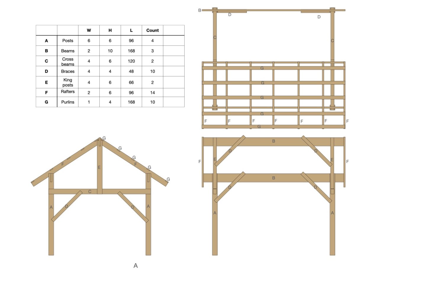
-
Timber-framed outdoor kitchen - Cathead - 1:1 scale
Cathead replied to Cathead's topic in Non-ship/categorised builds
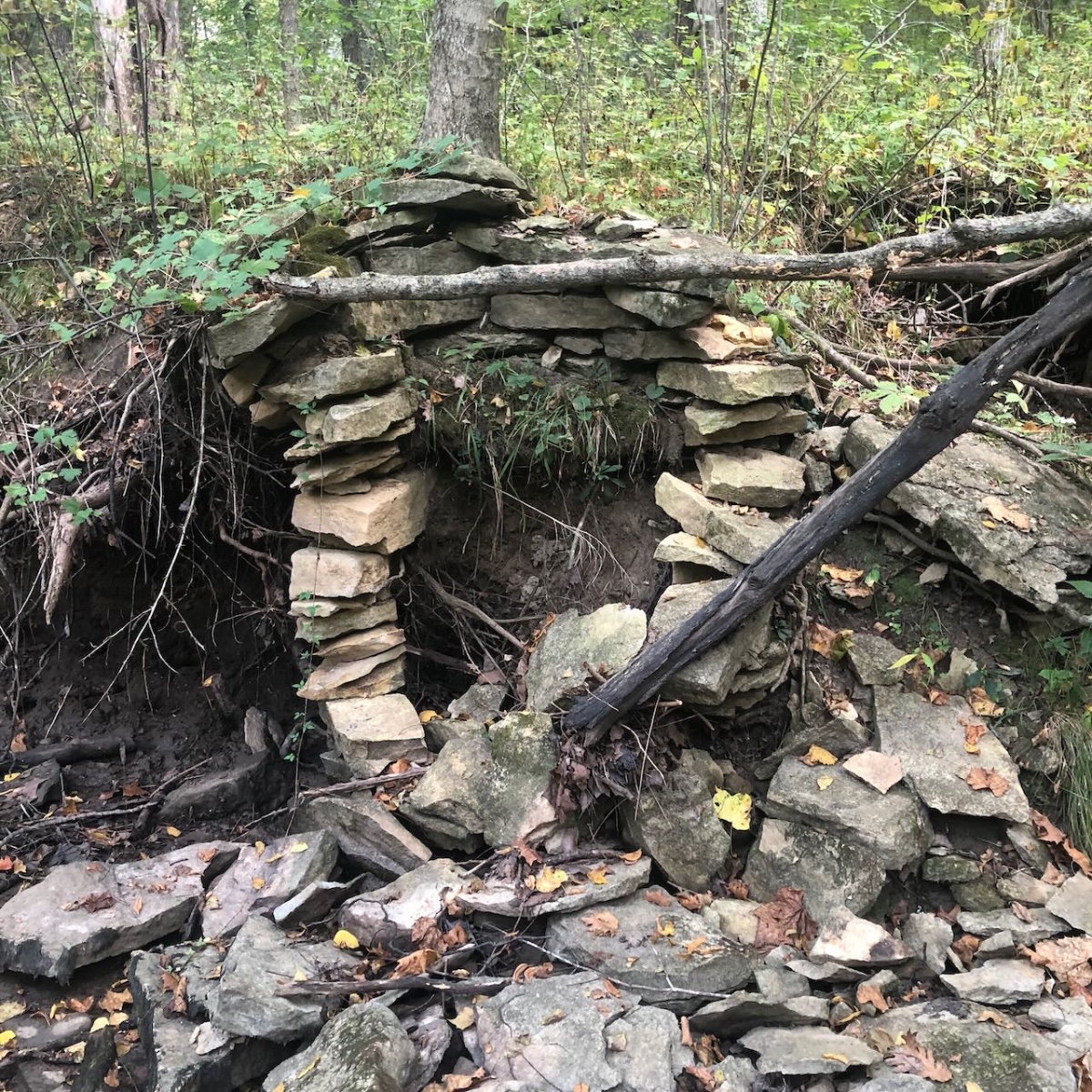
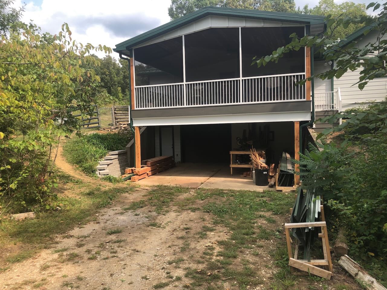
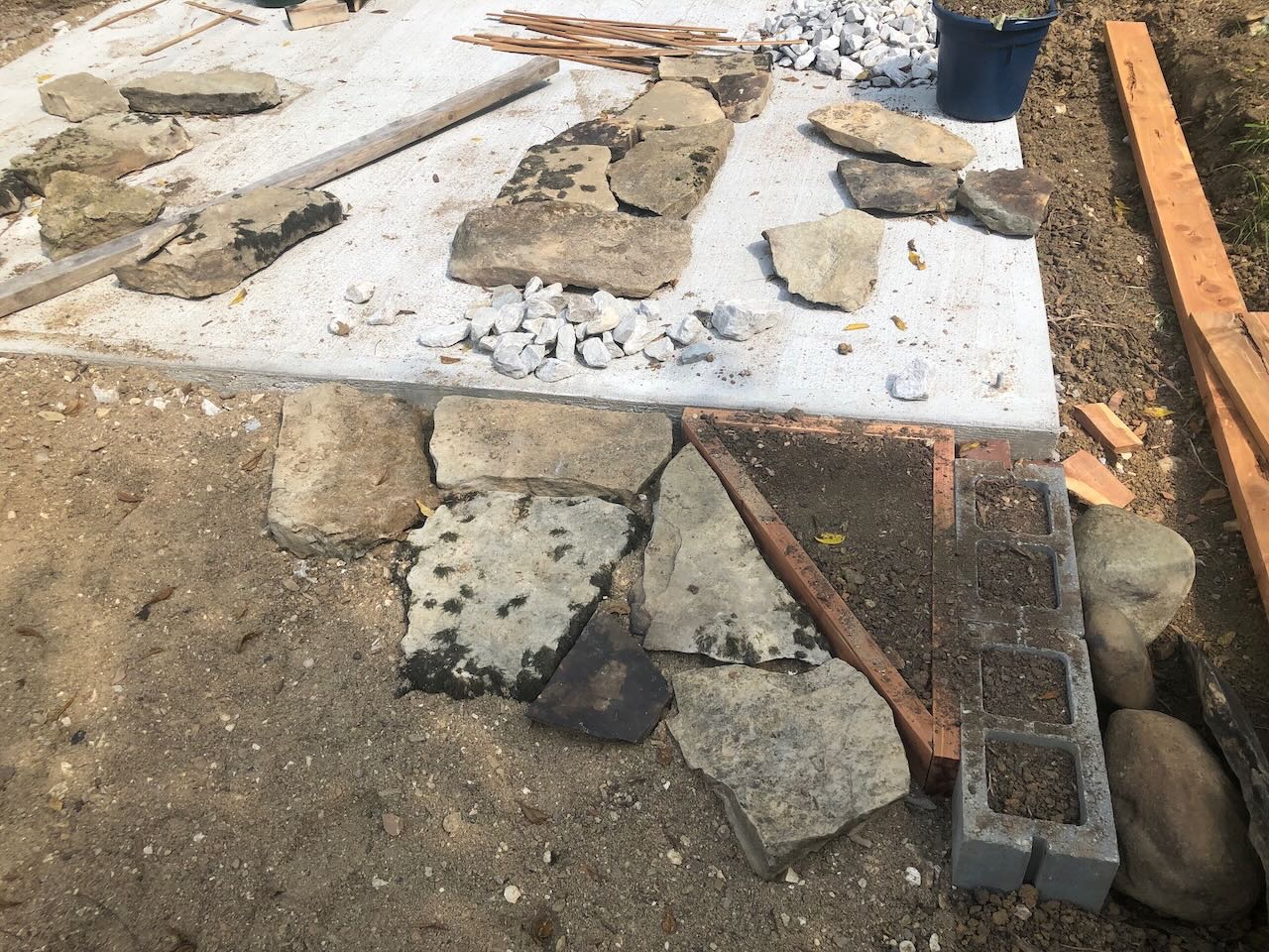
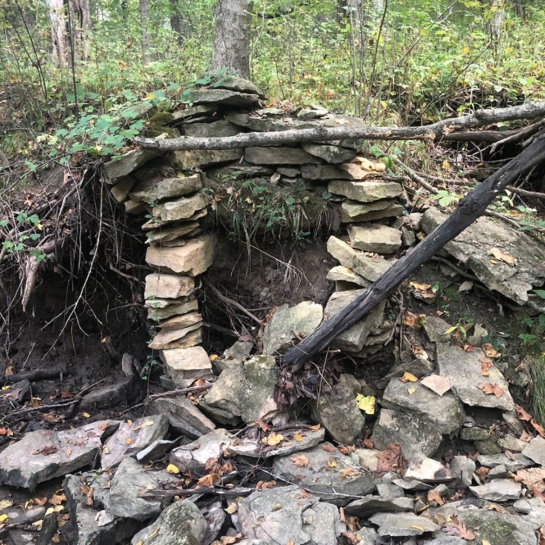
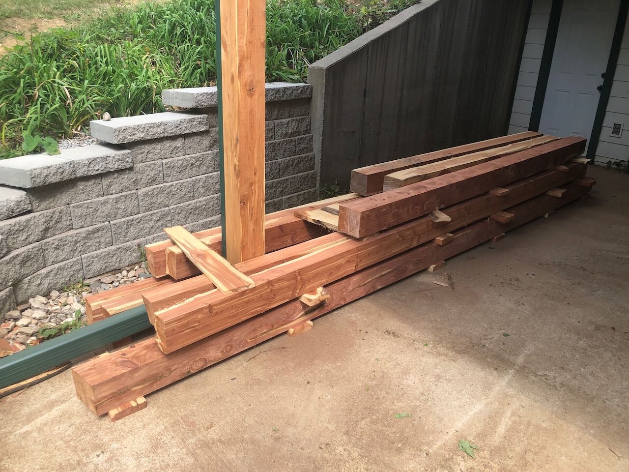
Worksite Here's the actual construction site, just outside our home kitchen and adjacent to our herb garden. We hired a crew to pour the concrete slab (not my forte) but are doing everything else ourselves. On the right side we're laying stone to connect over toward the house, using slabs of limestone collected from our creek valley. There's actually some fun recycling going on here; there's an old hand-built stone cistern along the creek, built by much earlier homesteaders, that has been collapsing as the creek shifts and eats into it. We're leaving the remainder of the structure alone, but harvesting the eroded slabs that are already washing downstream and no long associated with the cistern. So not only are we getting nice slabs that someone else selected long ago, we're keeping their work alive by repurposing it rather than just letting it wash downstream. Other slabs we're harvesting ourselves from loose creek rock. For the geology-minded, this is all Pennsylvanian-era limestone; we also have copious shale and thin coal beds from the same era. Cistern and view downstream from the same location: Much of the woodworking will be done in my outdoor workshape space below the screened-in porch; you can just see an initial post pile to the left and a workbench to the right. This has enough floor space to lay out a full frame at a time and do all the joinery/cutting needed, before taking the final pieces up and around to the kitchen site for assembly. There's some nice shade here, which will be great because we're forecast for near-record temperatures in the mid-upper 90s early this coming week. My stepfather arrives this evening and we'll get to work on Sunday, with the goal of having a bunch of pieces finished and ready to assemble/erect next weekend. We've invited various friends over for an open-house-style barnkitchen-raising, so the pressure is on to get work done! Should be a fun party, though, with lots of on-farm food and homemade mead and fruit wine on hand.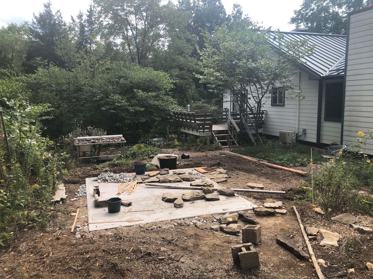

- 131 replies
-
- 14
-

-
Timber-framed outdoor kitchen - Cathead - 1:1 scale
Cathead replied to Cathead's topic in Non-ship/categorised builds
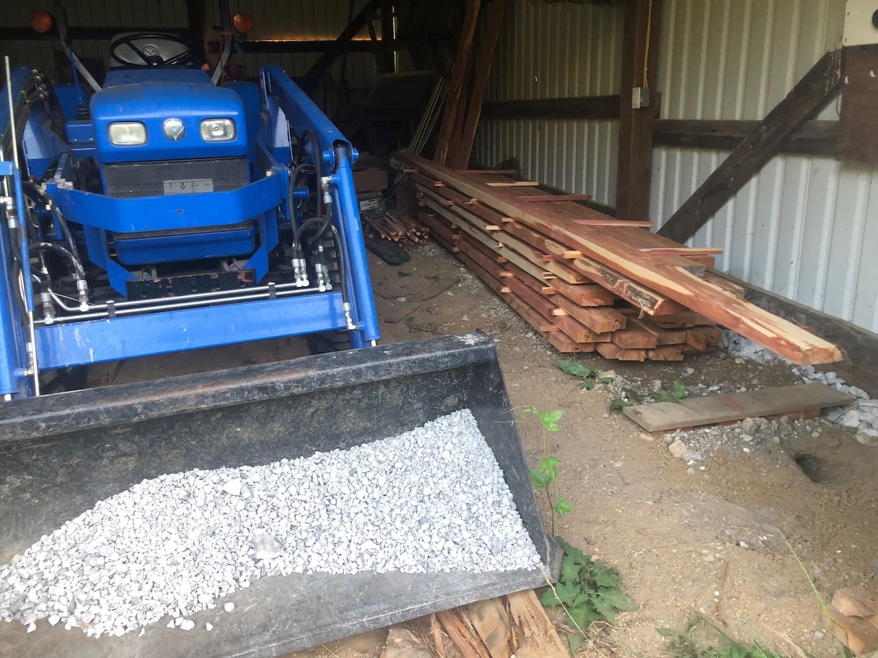
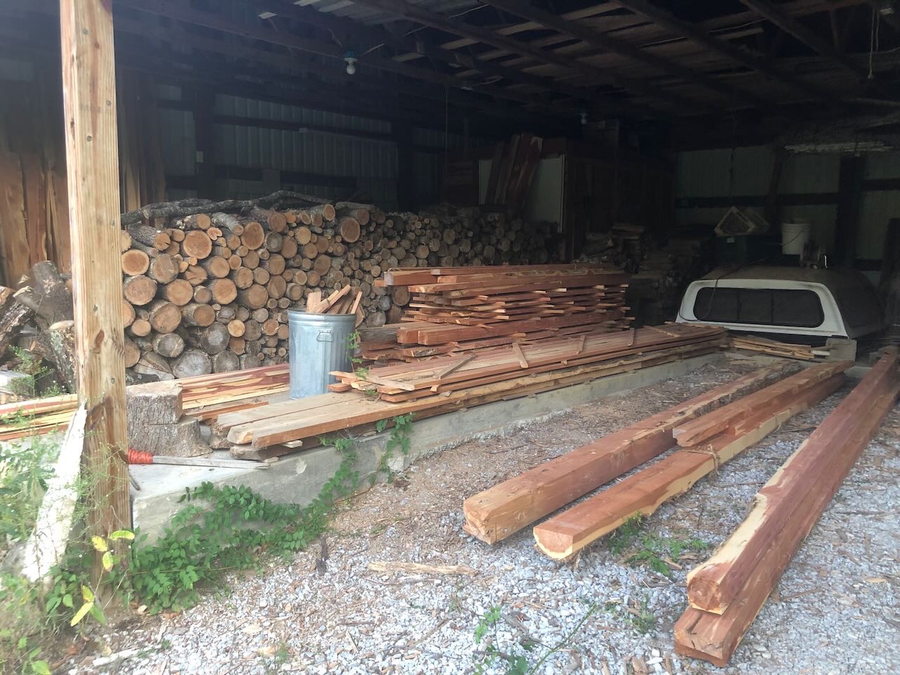
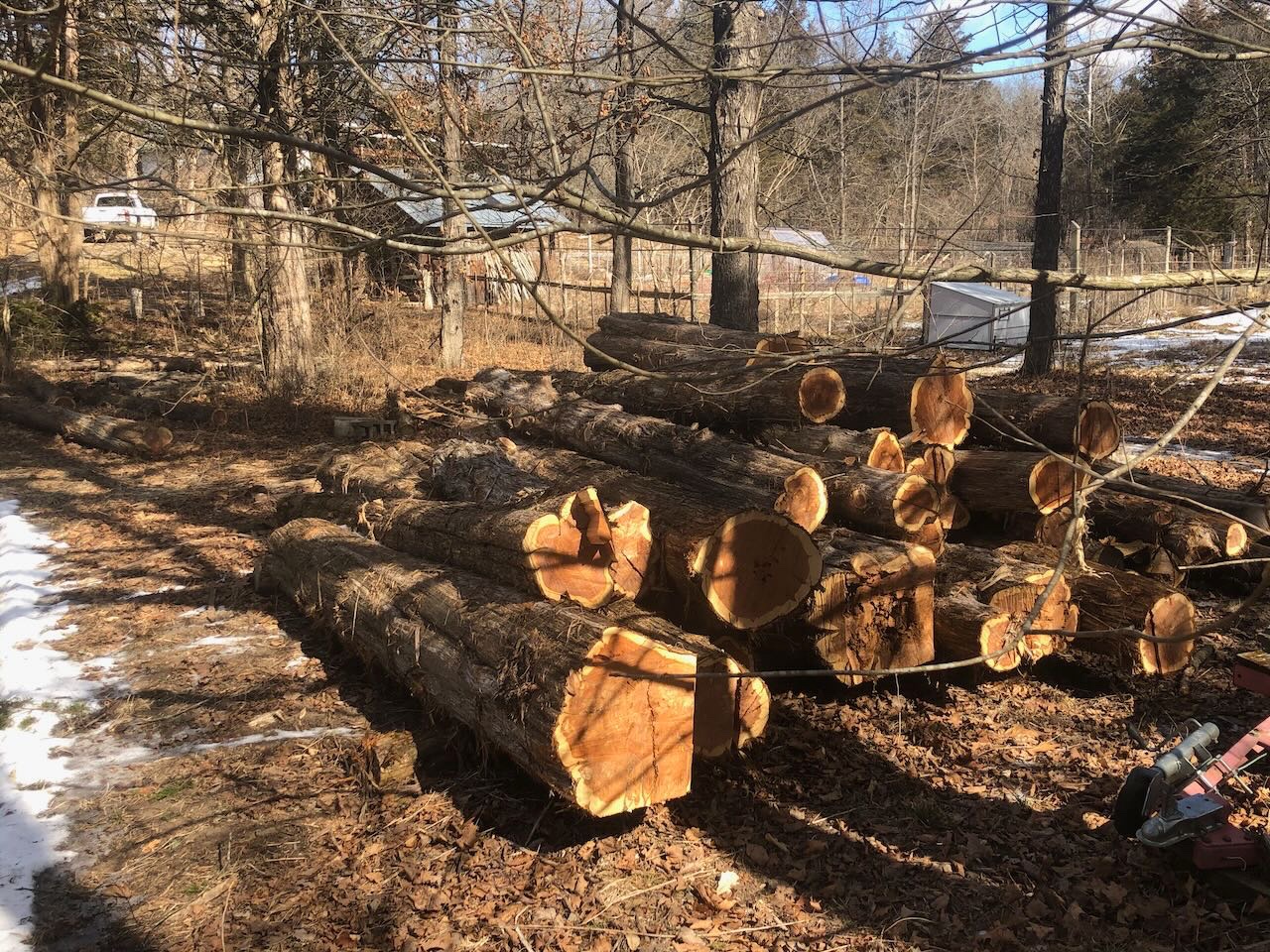
Milling We've always brought in a hired portable bandsaw service to mill our logs, the only part of the process we don't do ourselves. So in late winter and early spring, they made two visits and milled up a big 'ol pile of cedar lumber that we sorted and stacked in our barn to cure. This meant I had to pre-develop all my plans for this and other projects, since we needed lots of custom cuts and weren't going to be running to a big box store for more home-cut lumber. But that's nothing new, we've been doing it this way for 15 years here. This lumber has been curing all summer and is now ready to go. I've broken down the piles, resorted them, and started staging different cuts for different stages of the built. I've also been completing some other minor building projects, such as Adirondack chairs and a dining table for our new screened-in porch, also built this summer (by a contractor this time). Here's some of the lumber sorted and staged.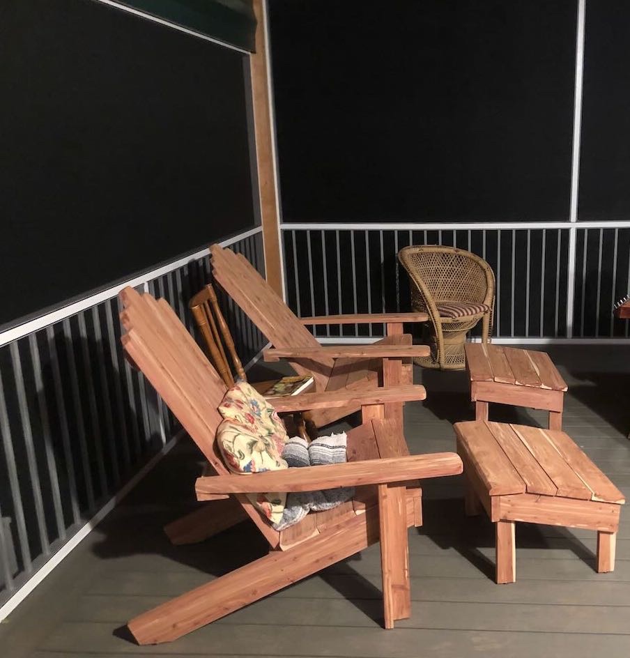
- 131 replies
-
- 14
-
-
Timber-framed outdoor kitchen - Cathead - 1:1 scale
Cathead replied to Cathead's topic in Non-ship/categorised builds
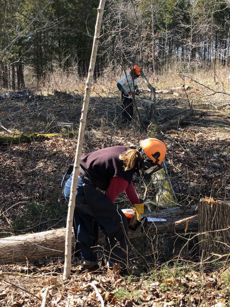
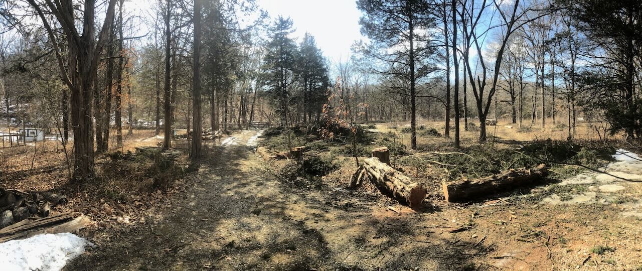
Timber harvest Over the winter of 2021-2022, we logged out the cedars we'd need for this kitchen and a variety of other building projects. Much of this came from a grove along our driveway, which we wanted to clear and replace with deciduous trees. Here's the clearing work partway along: Here are a couple log piles waiting for milling: We've always done our own timbering work, with the occasional exception of hiring someone to take down a tree that's particularly awkward (such as leaning toward the house or power lines). Toward the end of the logging season, I sustained a nasty hatchet injury to my wrist while doing cleanup work (we have a wood chipper and chip most of the branch material for on-farm mulch rather than waste it). This pressed Mrs. Cathead into service finishing up the last bits of chainsaw work, along with a helpful friend. The injury delayed the kitchen project from spring to fall; I've been able to recover to the point of doing all my normal weight-bearing work, though the wrist remains persistently (permanently?) stiff and sore. So the project is back on track.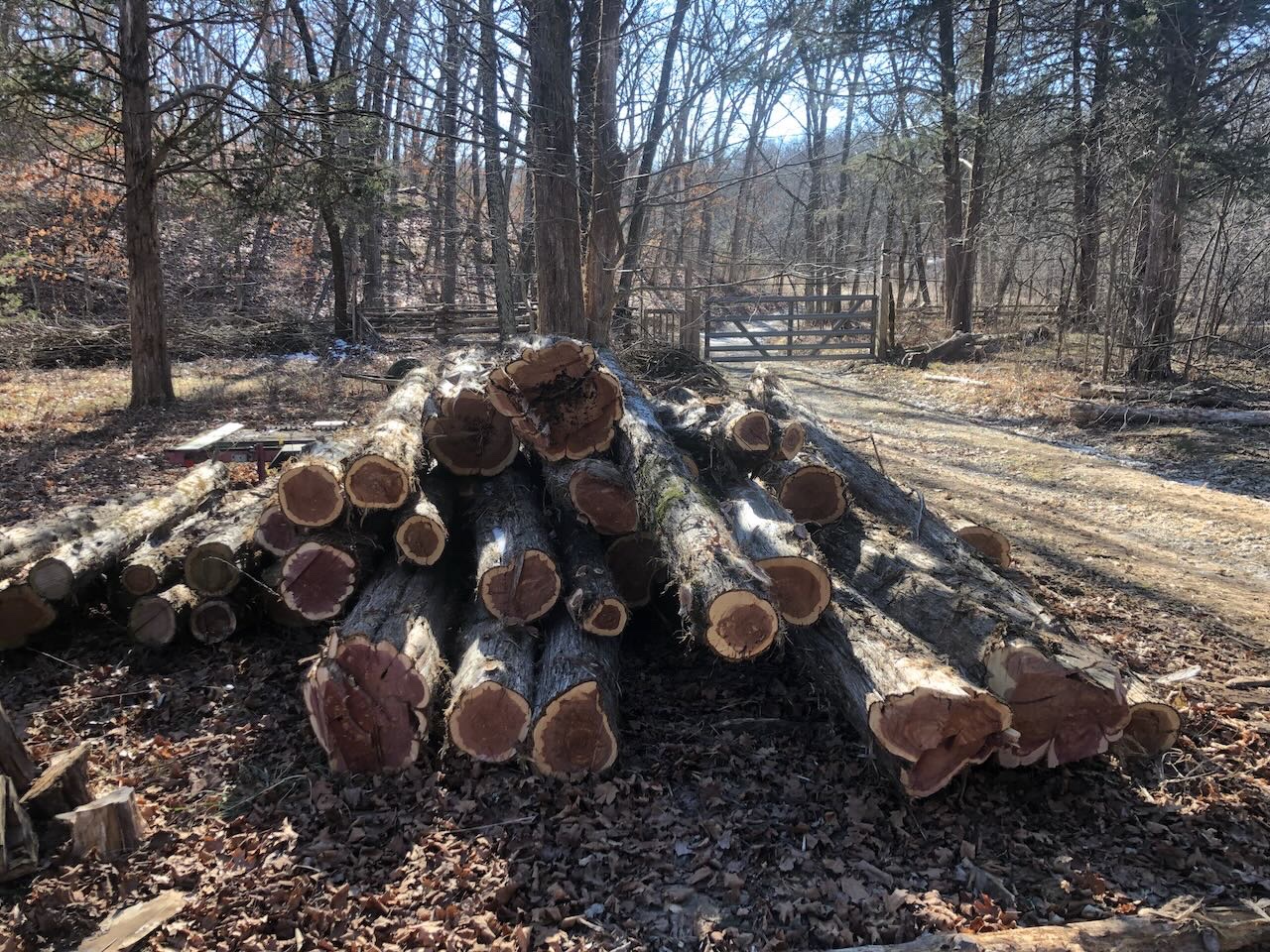

- 131 replies
-
- 14
-
-
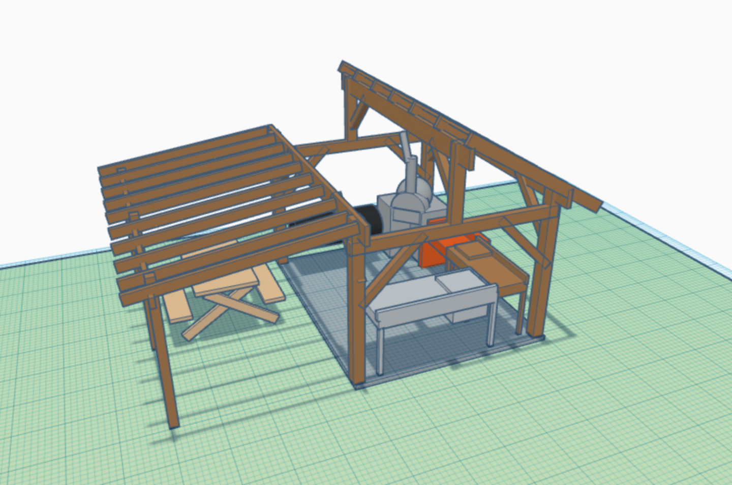
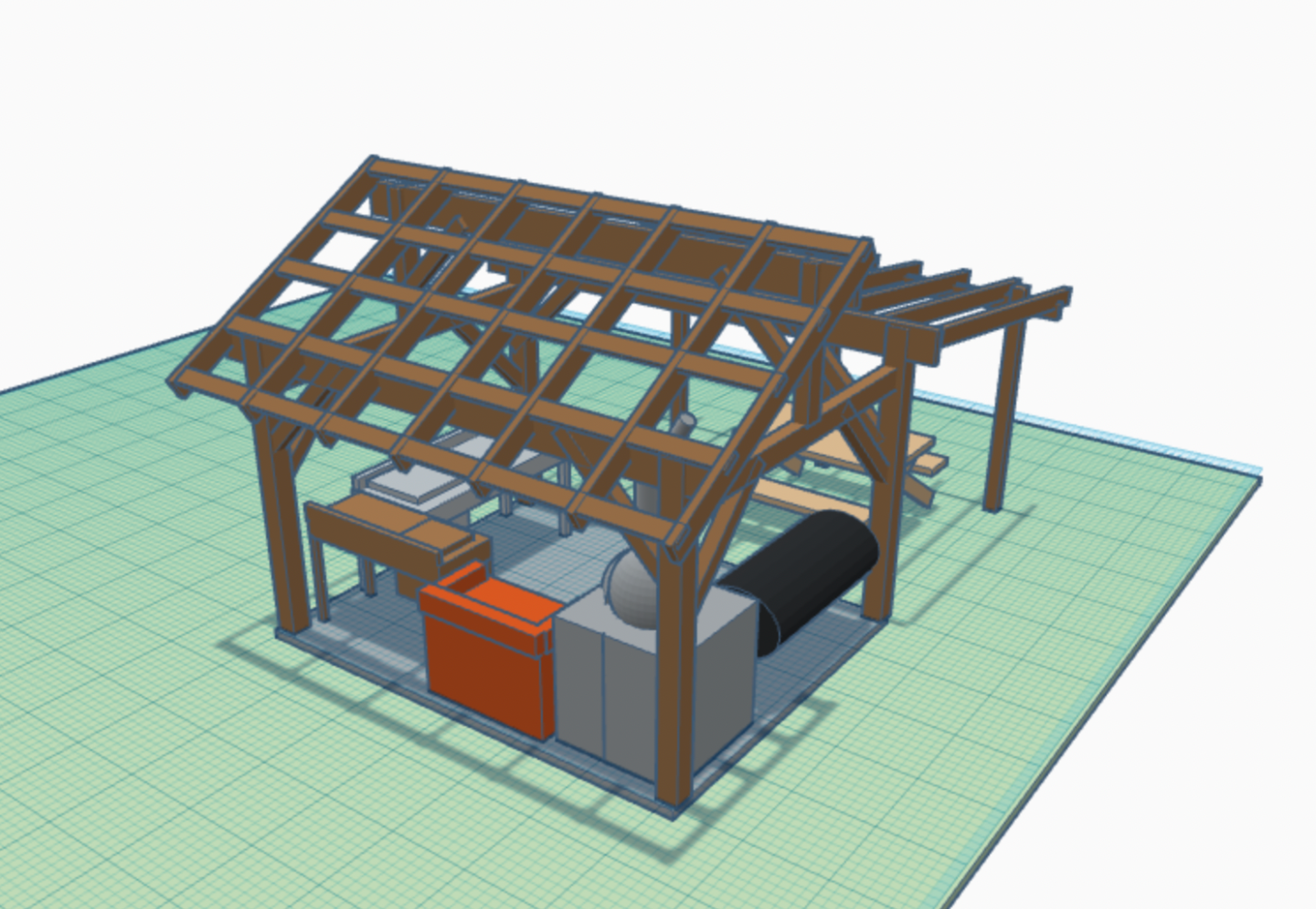
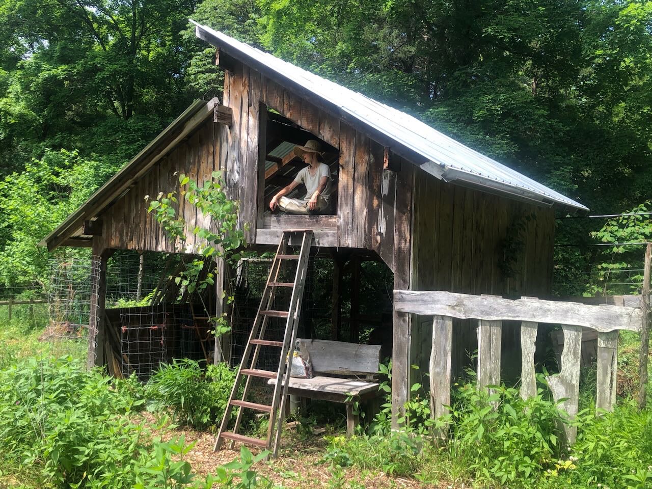
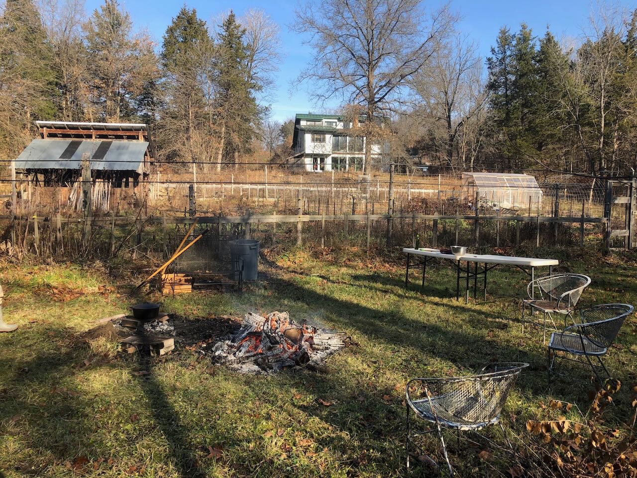
I've been encouraged by a few friends here on MSW to start a Shore Leave build log for this full-scale real-life project. I'm about to start building a 10'x12' outdoor kitchen on our rural Missouri homestead farm. It's intended to host a wood-fired pizza oven, wood-fired grill and griddle, smoker, and wash station. Here's a rough 3D rendering I developed when first designing this project (one half of main roof left off for clarity); the design has since changed some but the basic idea holds. We've long produced much of our own food here (all our produce, dried beans, flour corn, potatoes/sweet potatoes, and culinary/medicinal herbs; most of our fruit, meat, and dairy). We used to run this place as a full-time diversified organic farm, though we've now drawn back to producing just for ourselves, and have also dropped our domestic animals (pastured hogs, chickens, and dairy goats). The reasons for this are complicated but include regulatory burdens and aging parents, and I'm not going to go deeper. But we're still built around achieving self-reliance and sustainability on our rural property with its mix of woodlands, pastures, and fields. In addition to preparing excellent meals, this structure is intended to host and ease a variety of other life tasks here, such as: Boiling down maple syrup (which we've previously done over an open fire) Butchering deer and other meat (we do our own meat processing, both wild and domestic) Preserving garden bounty (such as boiling down large pots of tomatoes) The common thread here is to (a) move some cooking out of the house so we can (i) use our own firewood rather than purchased electricity and (ii) keep the house cooler in the summer, (b) have a protected area to do outdoor tasks that used to be more weather-dependent, and (c) have new ways to share the farm's bounty with friends and visitors. The kitchen will be built entirely from Eastern Red Cedar lumber harvested and milled on-farm. We've done timber management work ourselves on this property for over 15 years, milling all the lumber we need to built the various outbuildings, barns, fences, furniture, and more that we've needed, and sometimes selling lumber for things like siding, decks, and other projects. Most of what we harvest is cedar, since it's an invasive-acting native tree that rapidly colonizes abandoned or disturbed land and is best removed in order to restore an oak-hickory savannah landscape that's more natural and productive for Missouri. Here's a broader view of our home and primary garden, and a closeup of one of my previous cedar buildings. There's an orchard up the slope behind the house, and a larger field off to the west (left). You wouldn't know it from the view, but we've cleared acres of cedars from the landscape and there are so many more to go in the restoration process. Although I've been building with farm-harvested cedar for a long time, this kitchen project will be a bit new, as I'll be integrating some timber-framing methods into the design rather than just relying on metal hardware to hold things together. It's a bit of a hybrid approach that I'll explain more in a separate post. Hopefully it goes well and justifies my sharing the work in a log; it makes me a little nervous to do so, but so be it. Much of the core work will be happening over the next few weeks, so we'll see how good I am at keeping this updated. Thanks for reading.
- 131 replies
-
- 15
-
-
6x6 posts, 4x6 cross beams, 2x10 lengthwise beams, 2x6 rafters, 10x12 footprint. May seem over-engineered but as cedar is a coarse-grained softwood I wanted sufficient space/strength for joins. Not my first cedar building. Don't want to go into more detail to keep this thread reasonably on track. I'll consider the separate log, I wasn't going to so I could just enjoy the experience, but I can see an argument for documenting as I go, even if the posts come late.
- 113 replies
-
- 4
-

-
-
- Cairo
- BlueJacket Shipcrafters
- (and 1 more)
-
That makes sense, like you said, it's simply a base layer for a final smooth hull.
- 111 replies
-
- 3
-
-
- Nonsuch 30
- Model Shipways
- (and 1 more)
-
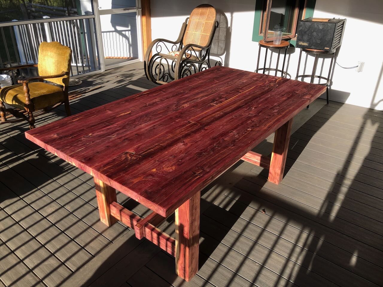
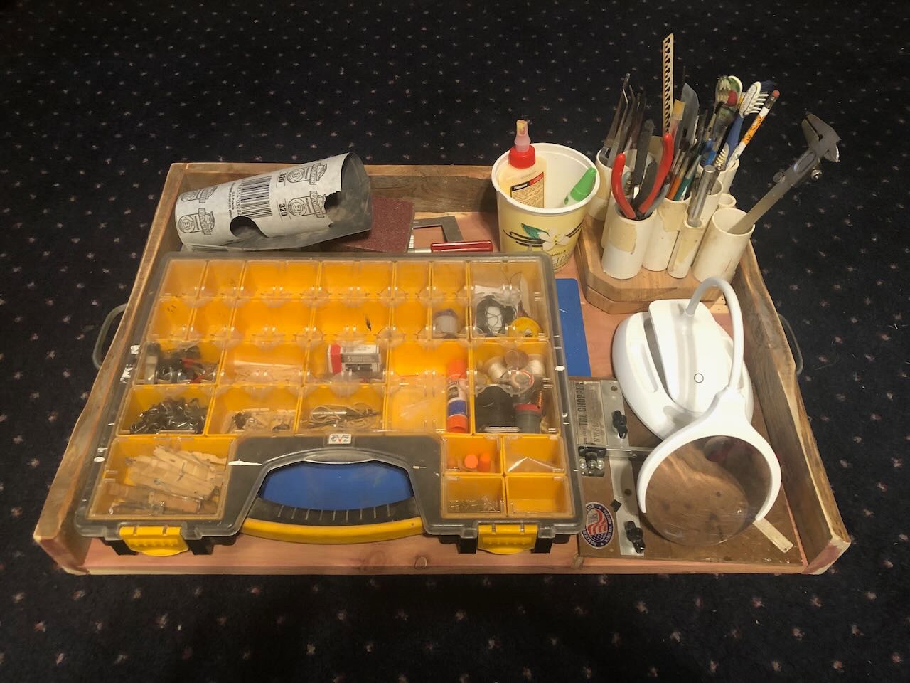
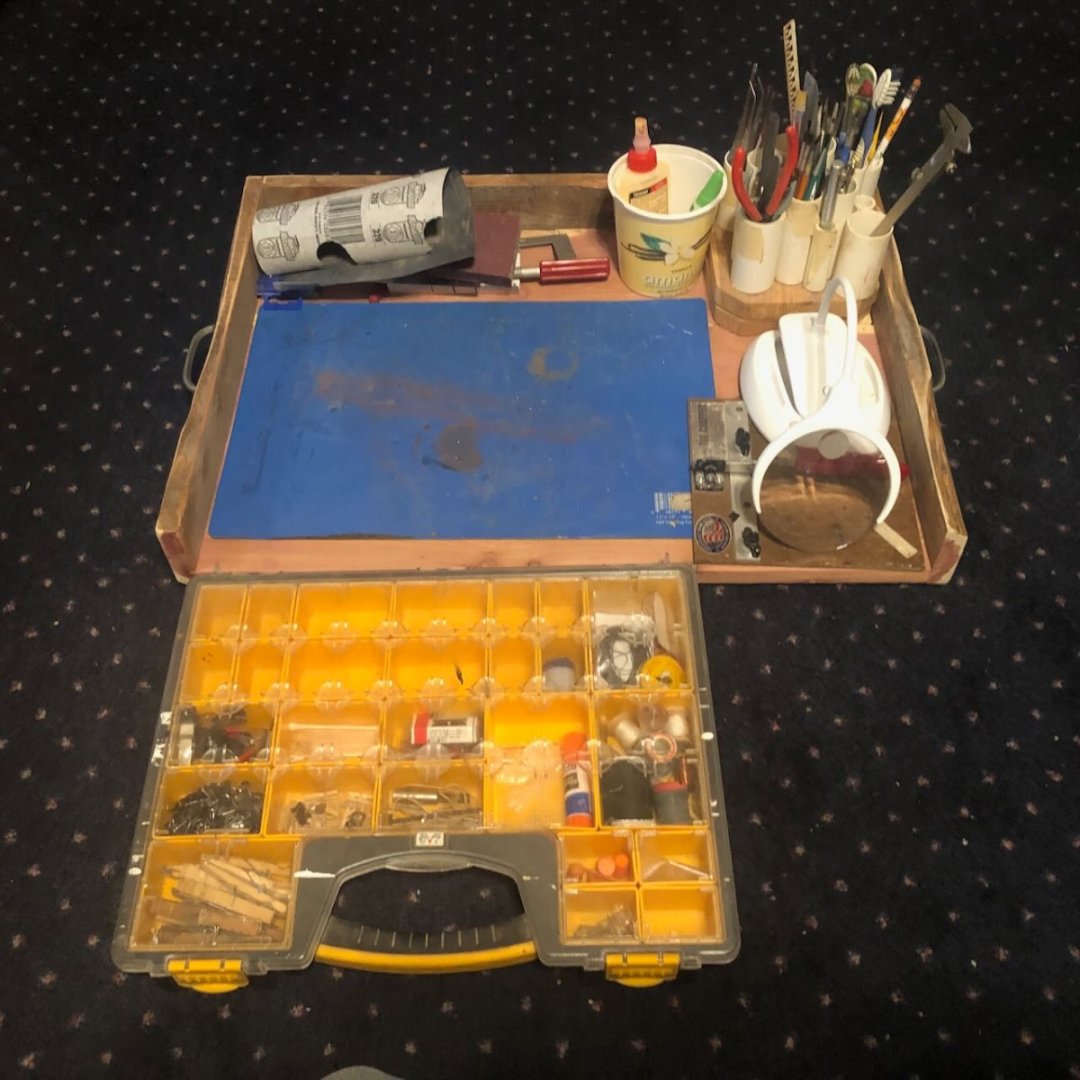
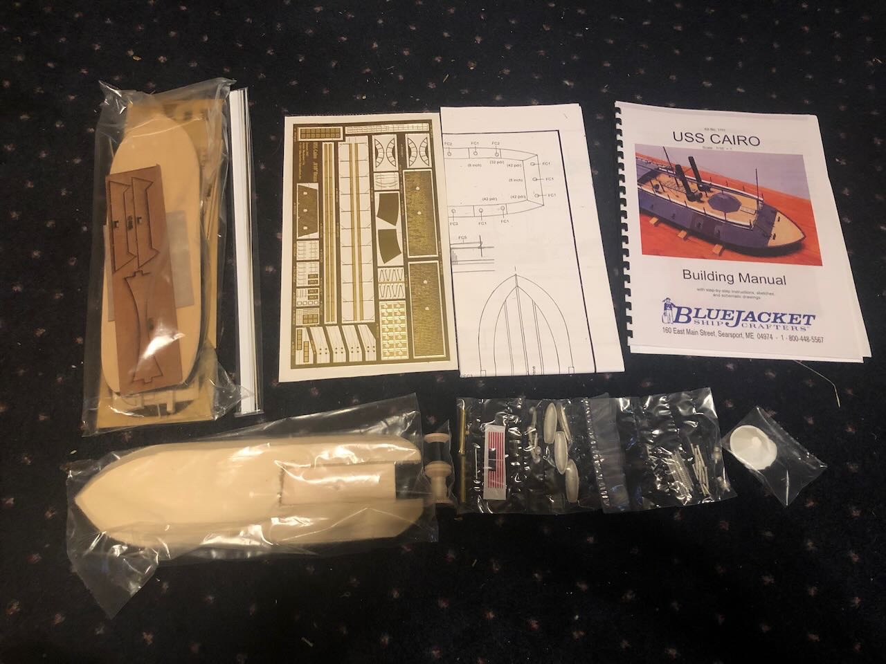
Thanks for all the well-wishes. It was definitely quite the saga. It's still stiff and (at times) sore, but I've been able to return to normal work, including 1:1 scale construction. Workspace Starting this log when I did was a bit of a bait-and-switch, as I'm not sure how much actual work I'll get done on this model in the next few weeks. I've been working hard to catch up on lots of other projects, and my stepfather (a nearly retired professional woodworker) is about to arrive for a two-week visit during which we're going to build a timber-framed outdoor kitchen together. But I was so excited to start my first model since last winter that I just had to dive in. The first step was creating a setting in which I could work on the model. As noted above, my normal workbench/shop is all packed up. So I threw together this portable work tray from scrap wood, on which the essentials can stack: The storage unit can then be unpacked, leaving a nice work mat free: This will let me move around the house and work wherever desired/practical. This idea/plan also factored into buying a small-scale model like the Cairo, which is less than a foot long. Unpacking With that ready, I can unpack the kit. BlueJacket has a nice unboxing/content video, so I won't go into details, but here's how the kit contents appear right out of the box. Solid wood hull, sheet of brass details, cast metal details, some strips of thin material, big sheet of plans, instruction booklet: And if you were wondering, and at risk of derailing this thread again, here are some examples of the other 1:1 projects I've been catching up on now that I'm functional again. We added a screened porch to our house this summer, and the plan was always for me to build furniture for it. So here are two sets of newly completed Adirondack chairs and footrests, a small dividing table, and a full-size dining table, all built from Eastern Red Cedar we cut and milled on-farm. The outdoor kitchen will also be framed in on-farm cedar. And to swing back to the model again, I may even get to work on the initial steps with my stepfather. He's a lifelong woodworker who has incredible skills, and he recently built himself a full-scale rowboat, but he's never built a model and has been very interested in following my work. So it could be fun for us to dabble in this together while he's here. I'll keep you posted. At worst, I'll dive into it in October. Thanks for the support and interest!
- 113 replies
-
- 9
-

-
-
- Cairo
- BlueJacket Shipcrafters
- (and 1 more)
-
Having not built this, I can't quite envision the geometry here. Would it help to post photos from a couple different angles?
- 111 replies
-
- 1
-
-
- Nonsuch 30
- Model Shipways
- (and 1 more)
-
Nice to see you back! Good progress on the hull.
-
I think I used rubber bands with normal wood glue, but then again I didn't mount mine to a building board, making that more practical. So one question is, do you still need it mounted to the board? At this point the hull should be pretty stiff and you probably have all the measurements you need. If you were to remove it at this point, you'd have a lot more freedom to work with the rest of the planking and the cap rail. Just a thought. Also, you could try to use binder clamps mounted over the rail, as these have a flat surface that would hold the rail surface down but the two faces should (?) grab onto the planking below on either side.
-
I enjoyed visiting this ship a few years ago, even though the guide wasn't well-informed. Looks you have the makings of an attractive model, the carronade looks nice.
-
Polaris by JDillon - OcCre
Cathead replied to JDillon's topic in - Kit build logs for subjects built from 1801 - 1850
I recognize that wood from my crappy Corel build; it does split easily. I don't have any experience following manufacturer's video logs so can't really advise you there, though I'd think they'd be more helpful than written instructions simply given the 3D nature of most tasks. But I still wouldn't trust these kit makers to really think through how to teach people to do things, rather than just show them. I'd suggest taking some planking scrap and making a few mockups of the task, then practicing on those until you work out a tool/method that you can do. This is good advice for any task you're not sure of. Most kits have enough scrap that you can make small mockups of things. All you need is an inch of solid wastewood and a few 1/2" pieces of planking, just enough to make a joint like that on the transom and practice trimming it. Also, not sure what exact technique you're using, but think about what you're seeing when the wood splits and adapt to that. For example, how is the grain running, and can you change your knife angle to avoid catching in the grain? Or to avoid finishing the cut on an exposed edge where it's most likely to split? -
Polaris by JDillon - OcCre
Cathead replied to JDillon's topic in - Kit build logs for subjects built from 1801 - 1850
If you're talking about trimming the ends of planking sticking out past the hull/transom, you might consider getting a fine-toothed blade or just using a razor saw. Those can be more effective at cross cuts than a smooth blade, no matter how sharp. I've also used a pair of nippers (flat on one side) to cut off such a plank just outside the hull, then sanded down the rest. You don't want to nip right against the hull because of the slight crushing action nippers produce. If your planks are curling, you may be using too much glue. It takes only a very thin veneer of any glue (CA or PVA) to join wood face-face, and as glue is made of liquid, if you use too much that liquid has to go somewhere (either squirting out and requiring messy cleanup or being absorbed by the wood and causing deformation). Try applying a very thin bead of glue on a plank, then spreading it to a very thin layer with something like a brush or a piece of scrap wood. Test on scrap material first if you want, to generate a technique. You'll be surprised to work out just how little you need for a strong join. -
I know what you mean about it being daunting to read through lots of build logs trying to glean tips and info, it can be overwhelming and even just difficult to keep track of what happened in each log. And so many of us repeat that process individually. But I'm struggling to see how a broad guide to a given model would work from a practical sense. For one, there will be lots of different opinions on the "right" way to do things, and who decides which approach is recommended? Yes, there could be a list of options, but that gets even more complicated. Second, it would have to be regularly updated and maintained, and that takes unusual dedication from a volunteer of some kind. Third, it would be huge for anything but small or simple kits. And fourth, it would be absolutely daunting to tackle for more than a few kits. I once thought it would be a good idea to create a post/thread that tracked all the Viking ship builds out there, so people didn't have to keep searching for them. But even that never came to fruition as I just didn't have the energy or time to tackle it. I'm not saying you're wrong, or trying to be a downer. Just sharing my own thoughts as I've had similar contemplations.
-
Personally I think the color variations in planking look more realistic and visually engaging, but that doesn't mean it's the effect you want!
- 158 replies
-
- 1
-
-
- chaperon
- Model Shipways
- (and 1 more)
-
1:162 Robert E. Lee Steamboat - Scientific
Cathead replied to Snug Harbor Johnny's topic in REVIEWS: Model kits
How many treenailing dowels did you have to order for all that flooring? -
1:162 Robert E. Lee Steamboat - Scientific
Cathead replied to Snug Harbor Johnny's topic in REVIEWS: Model kits
Let us know when you start your build! -
Looks great, happy to follow along. Being also of Norwegian descent, I quite enjoyed building (and improving) my Dusek longship.
- 75 replies
-
- 1
-
-
- Oseberg
- Billing Boats
- (and 1 more)
-
@gak1965, it most certainly is a hammered dulcimer (or more precisely, a stand and case; the dulcimer is set up behind the camera view)! That's hilarious, how similar our two settings are. If you're interested, I've started posting music videos on my YouTube channel, which mostly focuses on interpreting Missouri's geologic and natural history. But we should probably keep any further dulcimer discussion to private messages so as not to steer this thread into the shoals! I'd love to hear more about your playing. Brian, thanks, I knew you'd be in the gallery. I'm going to have to force myself to make compromises from your level of attention to detail or I'll never complete this thing! And I do want to get back to scratchbuilding. But it's going to be really interesting to see what I can adapt from your work into this tiny scale. Welcome to all others, too.
- 113 replies
-
- 5
-
-
- Cairo
- BlueJacket Shipcrafters
- (and 1 more)
-
Like you said, this is a tough build to learn on but you're spot on by sticking with it and doing your best. My bet is you'll be surprised by how well it comes together. Not only are we often our own worst critics, but a completed model has a way of hiding faults that seem apparent during the build process. And most people who see the completed model are more likely to say "wow, you actually built that?" rather than "hey, your planking's suboptimal".