Cathead
-
Posts
3,558 -
Joined
-
Last visited
Content Type
Profiles
Forums
Gallery
Events
Everything posted by Cathead
-
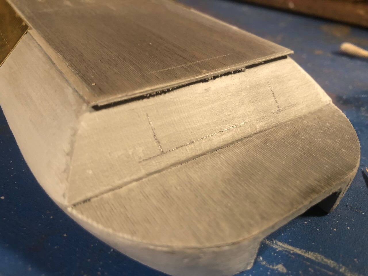
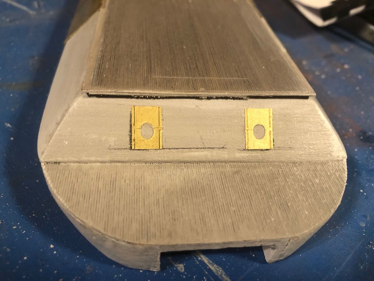
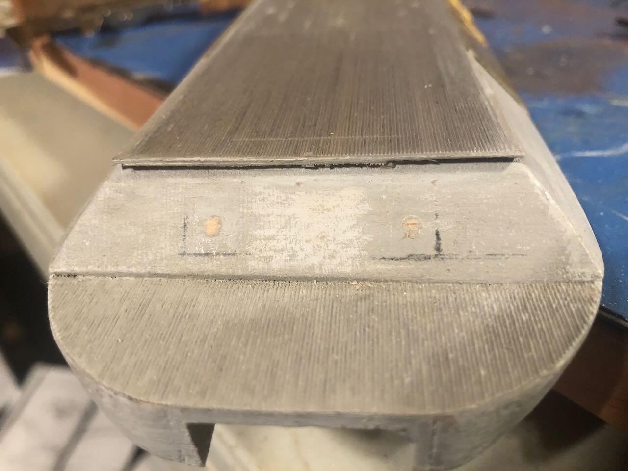
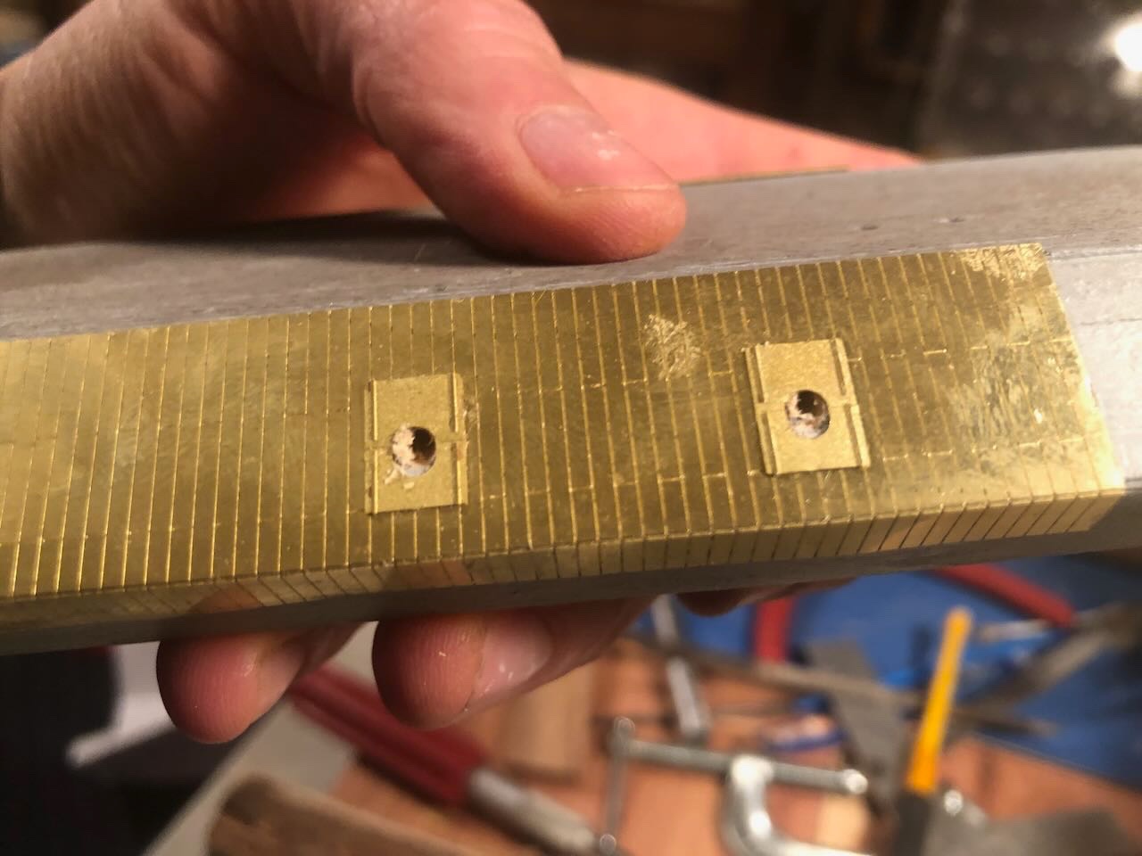
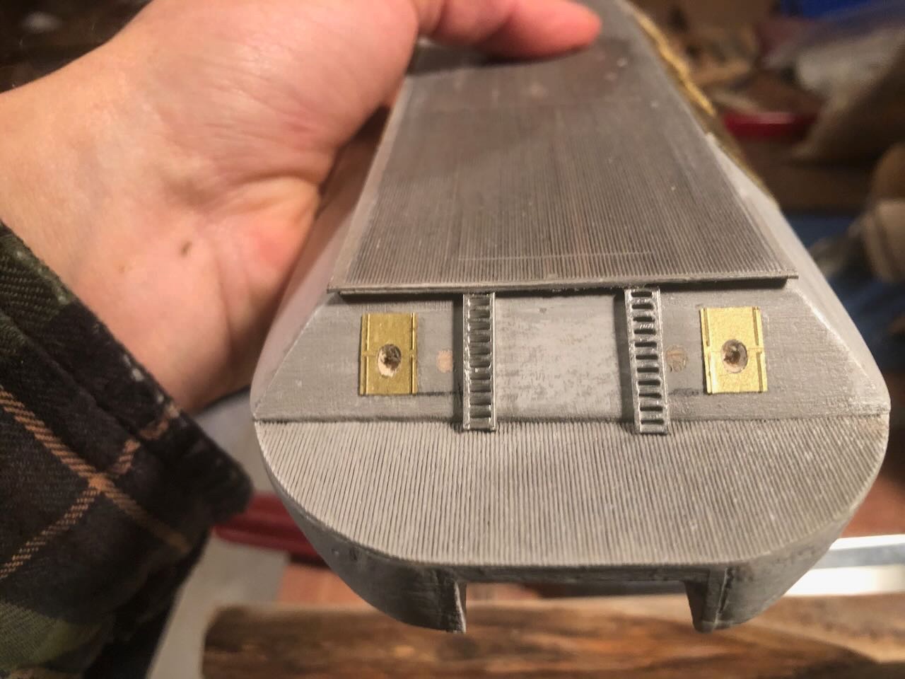
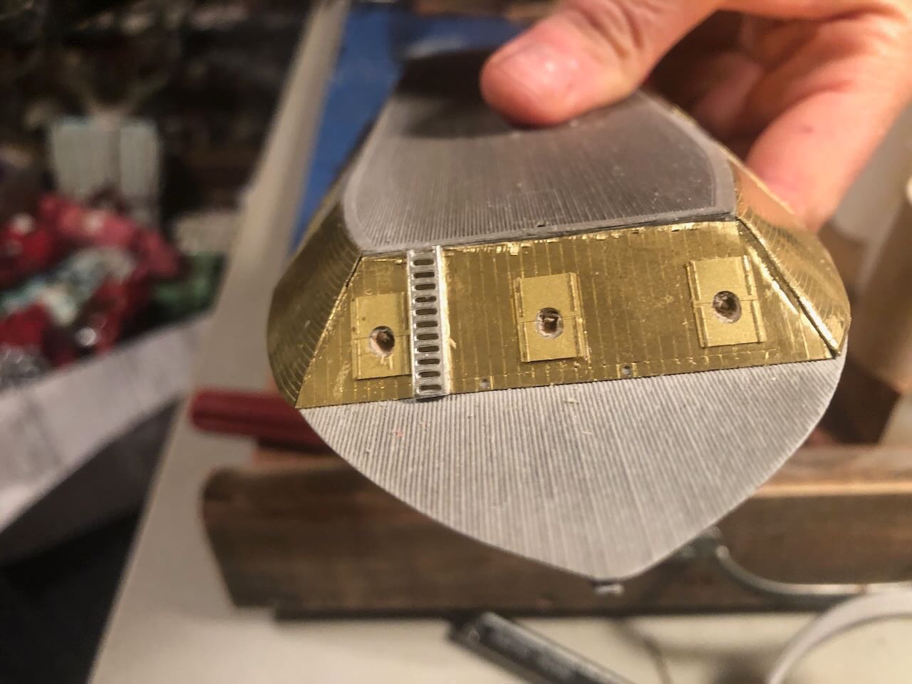
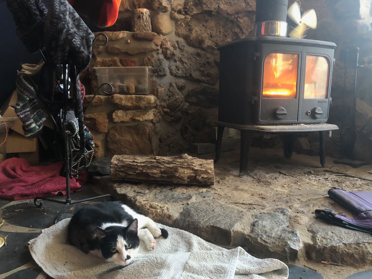
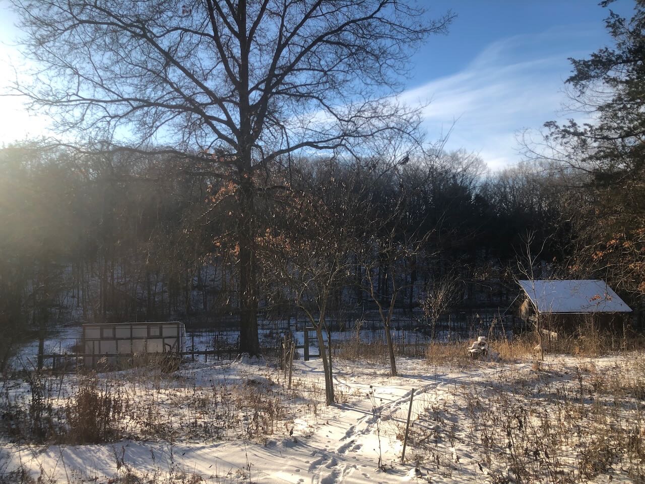
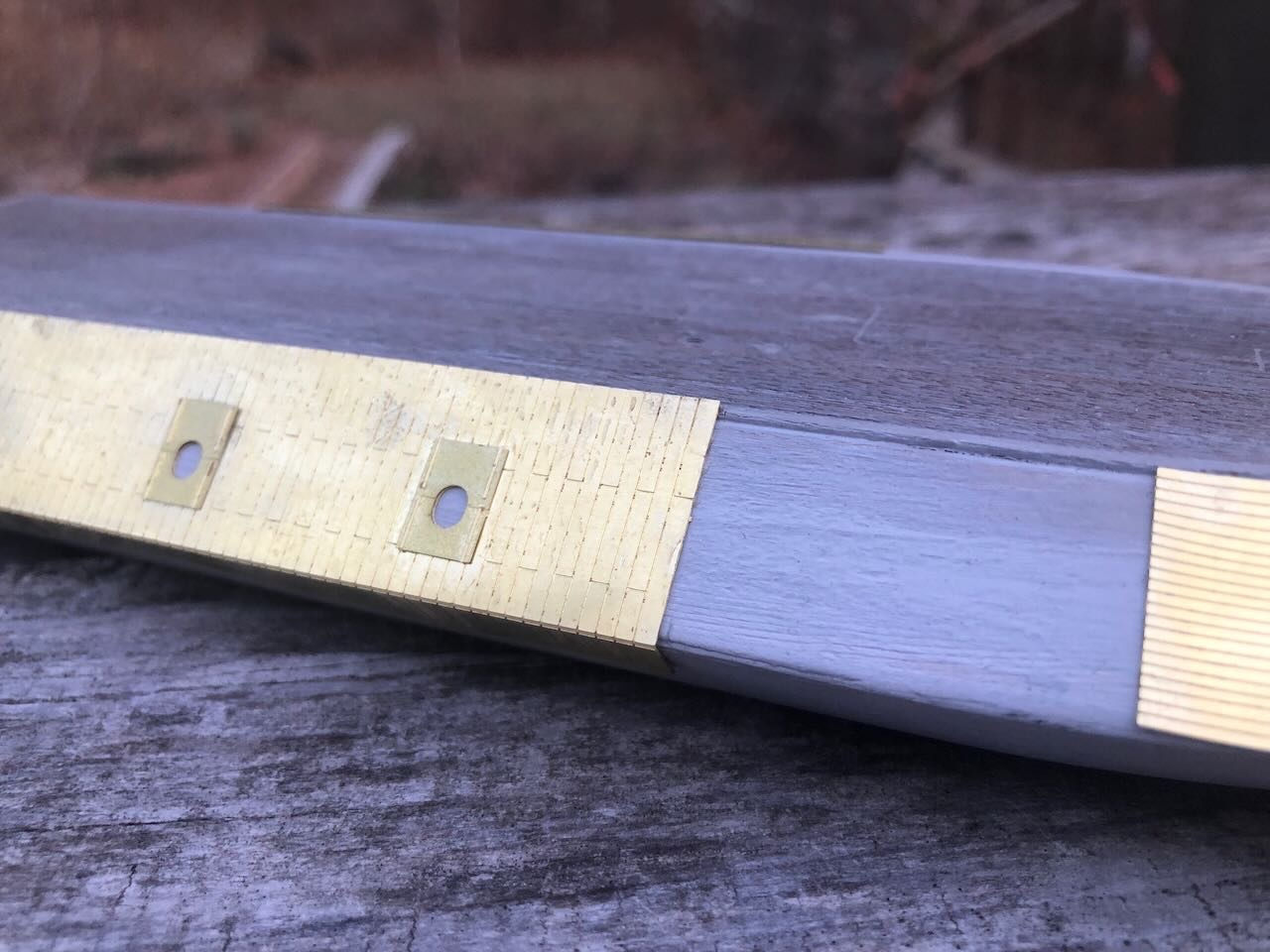
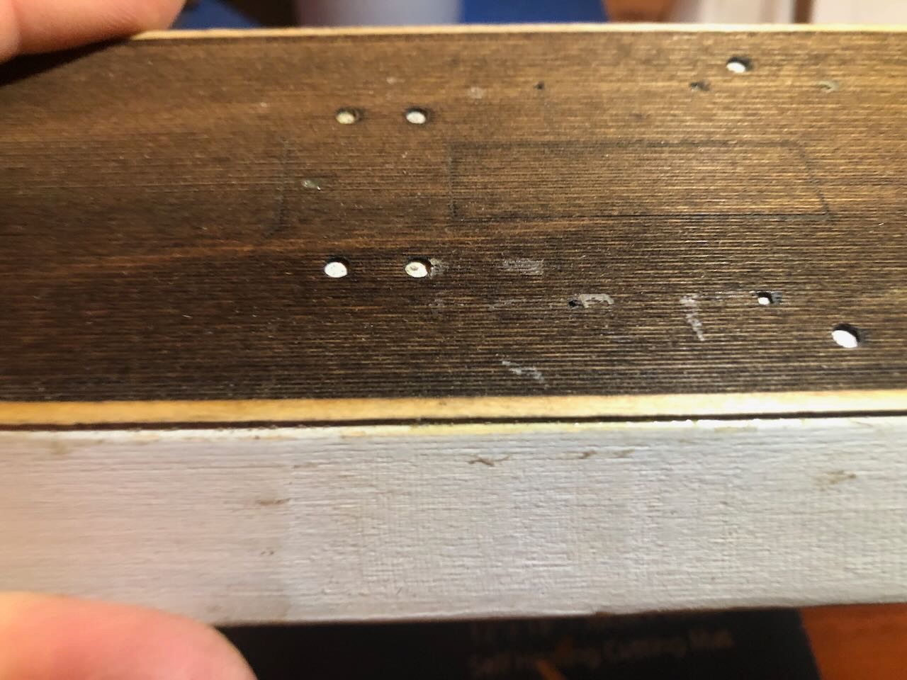
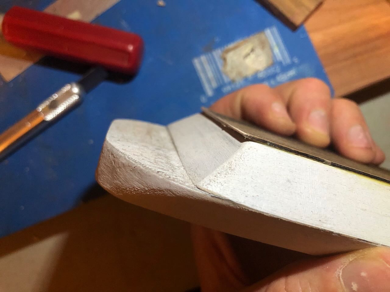
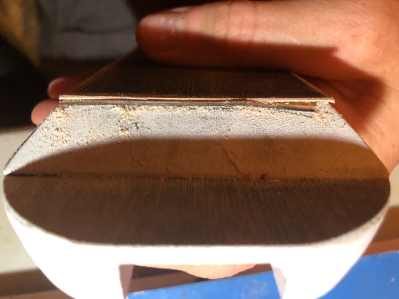
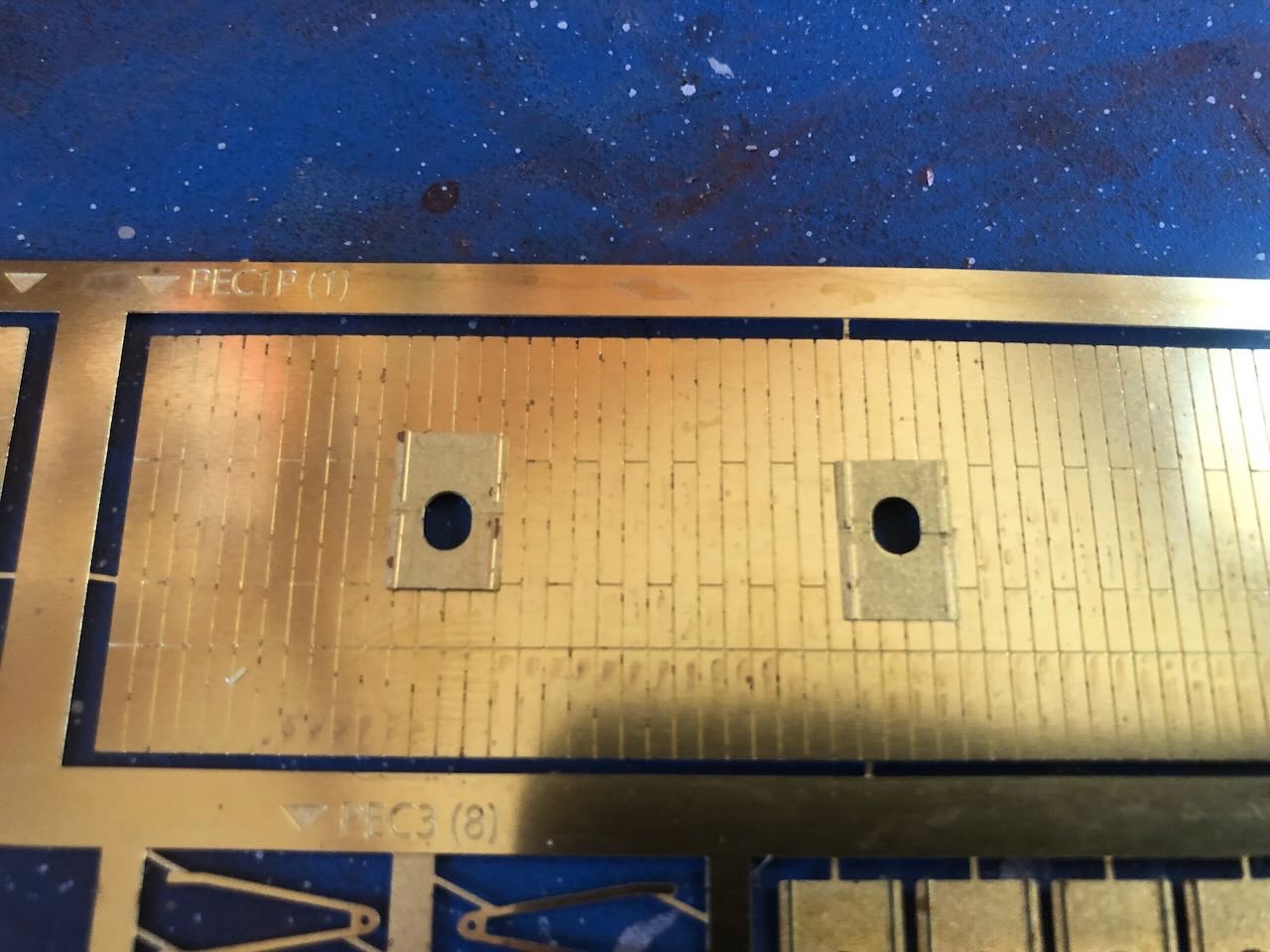
 Found another hour last night to dabble in this thing. The next step is to drill out holes that will later hold the guns, and attach the rest of the gunports (the ones that don't go on the armor). So I marked out locations for the guns and ports using calipers to transfer distances from the plans: Below, testing aft gunports. I used their location to set my drilling location (by the middle of the gunport). Anyone see a problem about to happen? Compare to the photo from @mbp521's log of where these go: Yeah, I set the ports on the wrong side of my location line, so they're much too far inward. They should be sitting outboard of the marking line, not inboard. Oopsie. Didn't notice this until after the holes were drilled and the ports glued on. So I chipped the ports off, filled the old holes with toothpicks and wood glue, and filed smooth. Hopefully they'll fade into the background under paint. Here's the updated aft casement, also with ladders attached. These castings are pretty rough but I'm not up for trying to rebuild something more to scale. Below you can see another looming problem. The kit has you drill different hole sizes depending on the size of the gun to be inserted. But some of these are smaller than the gunport opening, leaving extra wood showing behind the port. This will probably look odd since everything behind the port is supposed to be open. I didn't recognize this problem until after everything was glued into place. So I took a sharp knife and tried to carve a "cone" within the gunport to at least set the wood back a little, hoping all the black paint will create a collective shadow effect. It's a bit rough but the best I can do without damaging the brass. If I were to do this over, I'd use a small counter-sink bit or something to widen the mouth of every gun hole before gluing on the ports; this would create a smoother and more authentic negative space behind the ports while not interfering with gluing them on. Oh, well. But since the kit has you glue on the armor before drilling holes, that would require carefully locating all the ports first. Currently instructions have you glue the armor (and associated ports) on before doing any drilling, making the drilling very finicky so you don't catch the brass with the drill bit. You could locate all the gun locations first and drill them all out (so you could countersink everything) but that would require extreme precision on a small rough wood casement, because you can't adjust the armor the way you can adjust individual ports. Personally I'd rewrite the instructions to do these steps consistently; place your armor in its final position and mark ALL the gun holes, then drill them all before attaching the armor & other ports to the casement (rather than attach armor, drill holes through armor gunports and into raw wood, then attach other ports). Anyway, this is what I got trying to follow the instructions (and making my own dumb mistake). Side ports drilled through armor ports (again, very touchy as the drill size is very close to the opening in the brass): Fore casement with more holes carefully drilled through armor ports, and another chunky ladder. Top view: That's as far as I got. I think the next step is to prime and paint this whole assembly; I'm really hoping that subdues the various awkward stuff and helps blend it into a more appealing whole. Merry Christmas, Happy Holidays, festive solstice, or whatever your favorite approach is. Thanks for all your interest and support, both in logs and PMs, as I work through this. I'm stubbornly determined to produce something that'll look ok from 4 feet away in my display cabinet! As a final note, here's the view from Cathead Valley after our bitter winter storm blew through with the coldest December air here since the late 1980s. Luckily we have a well-supplied wood stove, also enjoyed by our current three-legged foster cat.
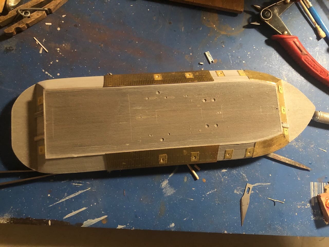
- 113 replies
-
- 16
-

-

-
- Cairo
- BlueJacket Shipcrafters
- (and 1 more)
-
Lovely! I completely agree that leaving the railings and bimini off produce a consistent open look to the model that shows off your detail and workmanship. A great example of what I often think about in model building re. the tradeoff between accuracy and artistry.
- 111 replies
-
- 2
-
-
- Nonsuch 30
- Model Shipways
- (and 1 more)
-
It may be slow and tedious, but at least it's not steamboat railings! Looks nice so far.
- 282 replies
-
- 3
-

-
- Bluenose
- Model Shipways
- (and 1 more)
-
Great prototype, I'll enjoy following along.
-
Confusing instructions are such a bane of the model world. As a freelance editor experienced in working with global clients, a few years ago I contacted various kit makers to propose having me review their instructions for both English language accuracy and general clarity. All refused, insisting that their instructions were fine. Sigh.
-
Great job on a complex build! She really came out nicely. Don't forget to show us the case when you get her in it! A nice addition to the steamboat library here on MSW.
- 238 replies
-
- 2
-

-
-
- Robert E Lee
- steamboat
- (and 3 more)
-
I don't know about the hot dog situation, but states' names get attached to products all the time without any meaningful connection. For example, "Vermont" gets attached to all sorts of food and craft products that aren't produced in or related to the state, because the state's image as a home to thrifty Yankee craftsmen is so strong. Vermonters hate it because it dilutes the value/brand of their actual products, but can't do anything about it. Virginia does have a strong cultural/historical connection to various smoked meats (like Virginia country ham), so it's possible the hot dogs you saw were using "Virginia" in the same way that "Vermont" gets used even if there was no state connection.
-
Brian, I can't come up with adequate words of congratulations. Just magnificent. I feel like I should say more but it'd just be word salad. I laughed out loud when I saw your towboat plan. I ended up following in your wake by starting a Cairo (of sorts), and I've had it in the back of my head that a modern towboat would be really interesting too, and well outside my normal range. So I guess I'll sit back and let you tackle that first, too! If we ever take our potential Oklahoma road trip, maybe I'll beg a chance to swing down across the Red River and see her in person?
-
Thanks Ian. At my glacial pace it'll be future years before anyone can benefit from a completed build! I'm still hoping I can come out with something that looks decent from a normal viewing distance. But life just keeps not letting me get to this.
- 113 replies
-
- 5
-

-
-
- Cairo
- BlueJacket Shipcrafters
- (and 1 more)
-
If it wasn't clear, that was a World Cup joke, not any sort of comment on your language skills!
-
Welcome! Might want to be gentle with the English members for a few days!
-
I agree that bending around a solid item is good practice, even if you can't find one with just the right radius. Getting a rough pre-bend in the wood makes final adjustment easier and safer. Nice work!
- 158 replies
-
- 1
-
-
- chaperon
- Model Shipways
- (and 1 more)
-
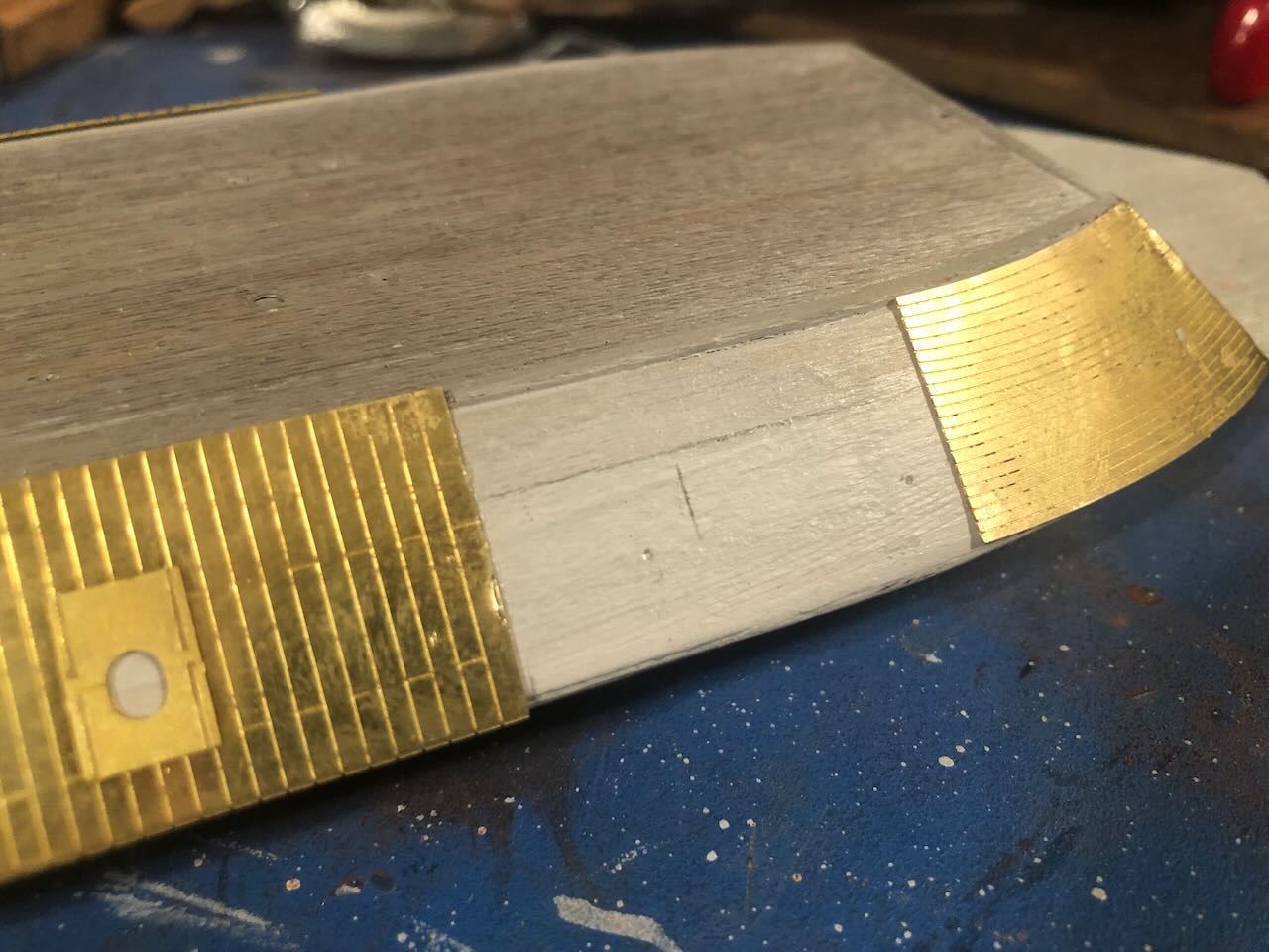
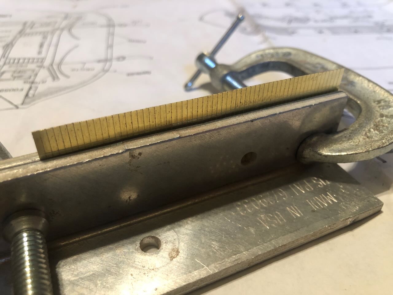
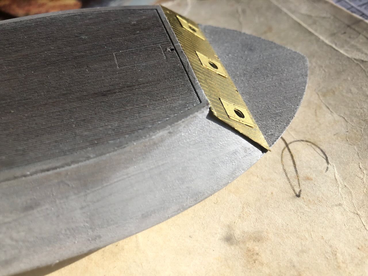
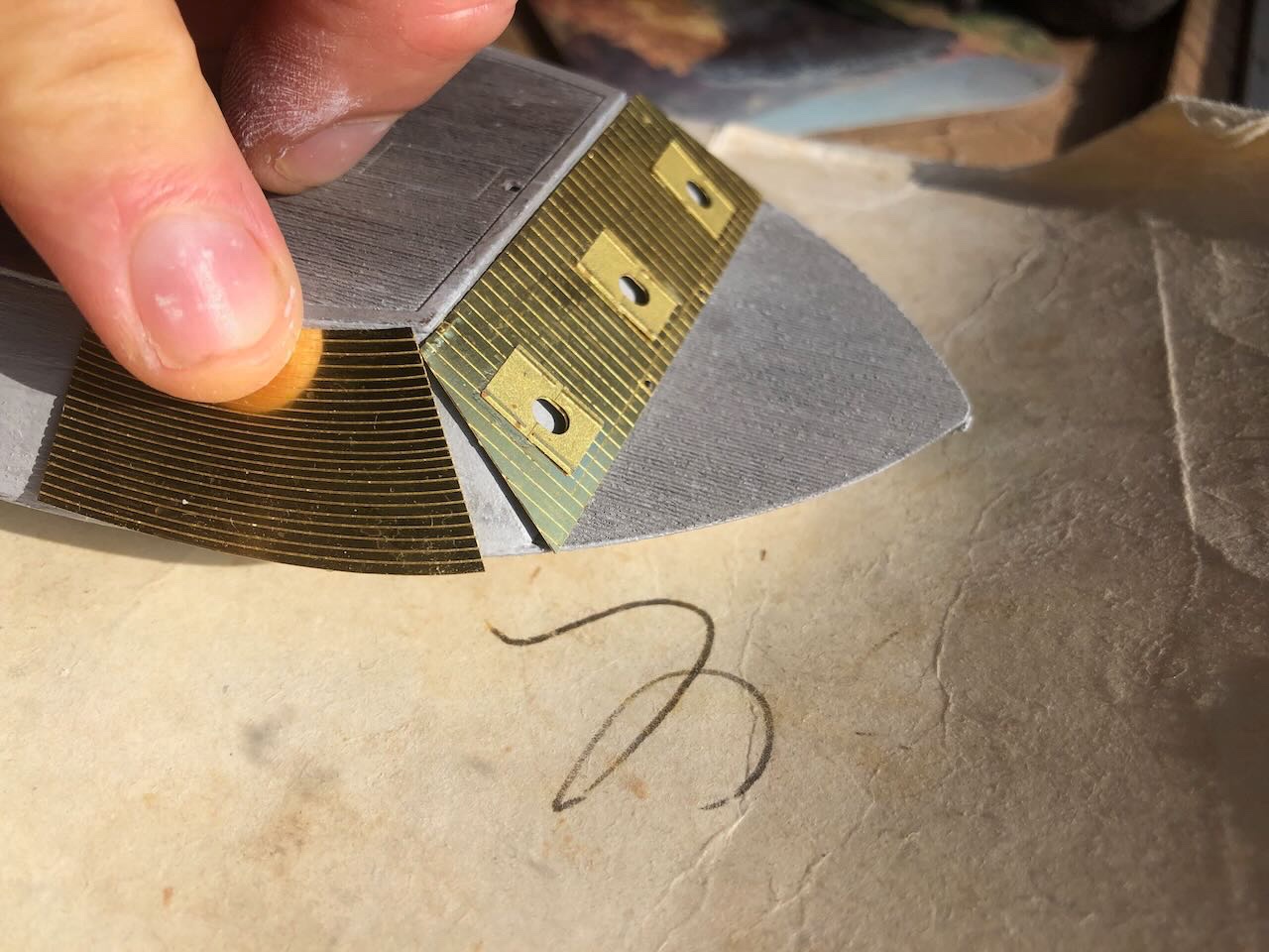
So I was in a stubborn, toddler-like "but I wanna work on my model NOW" mode after posting that. I remembered that I had a pair of model-railroad rail nippers, and decided to see if those would cut brass sheet. Definitely not ideal, they bent and mangled the edges as I worked, but I just went ahead anyway, and with some careful filing and flattening got a moderately workable result. You can see the mangling, but I think the bright brass makes it stand out more than when it's all dark and weathered. I had to cut and file a lot of material to make this fit reasonably well. This will definitely be a "view from a few feet away" kinda model. As you can see, I also added the side armor. This needed to be bent carefully in a 90º bend where it wraps from the casement onto the hull. I clamped the pieces between two metal squares and that worked pretty well. Another example of odd instructions, though, they tell you to glue the gunports to these armor sheets before you do the bend. But that makes an uneven surface in the clamp, and one of the gunports came off. I can't see why you wouldn't just glue the ports on after the sheets are bent, or even after they're on the model. Another problem was that the side armor came out at a different dimension than the front armor; it sticks up further past the hurricane deck. I think it's supposed to tuck in under that deck. I had no control over this because the bend happens along a pre-scribed line. I was not about to try and cut/clip a smooth line off the entire top of these long side armor sheets, so I just ignored the disparity and again hoped that paint and weathering and distance will obscure it. But it's another odd inconsistency about the kit's design. The hull and casement are just too small to allow the brass sheet to fit properly.
- 113 replies
-
- 7
-
-
- Cairo
- BlueJacket Shipcrafters
- (and 1 more)
-
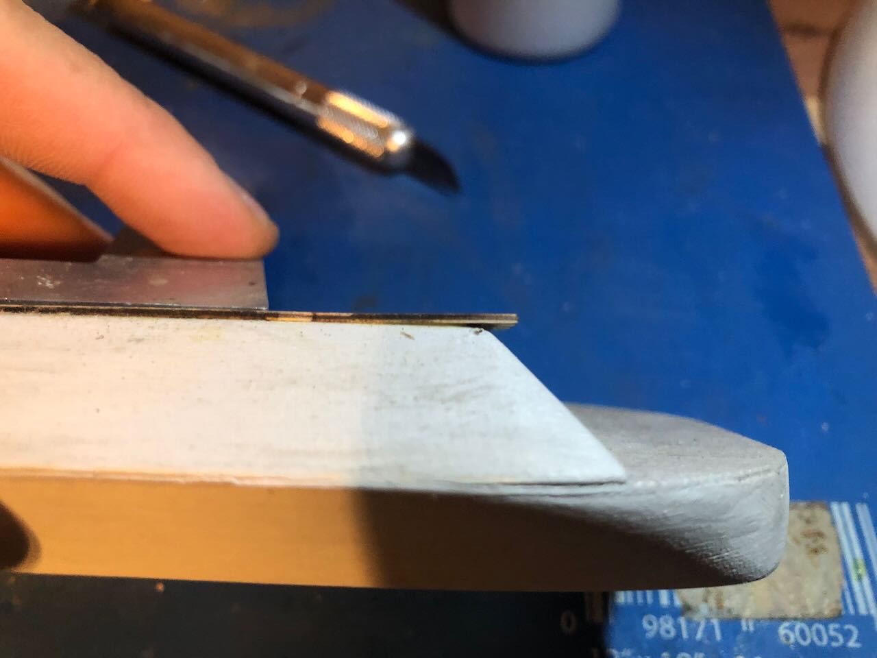
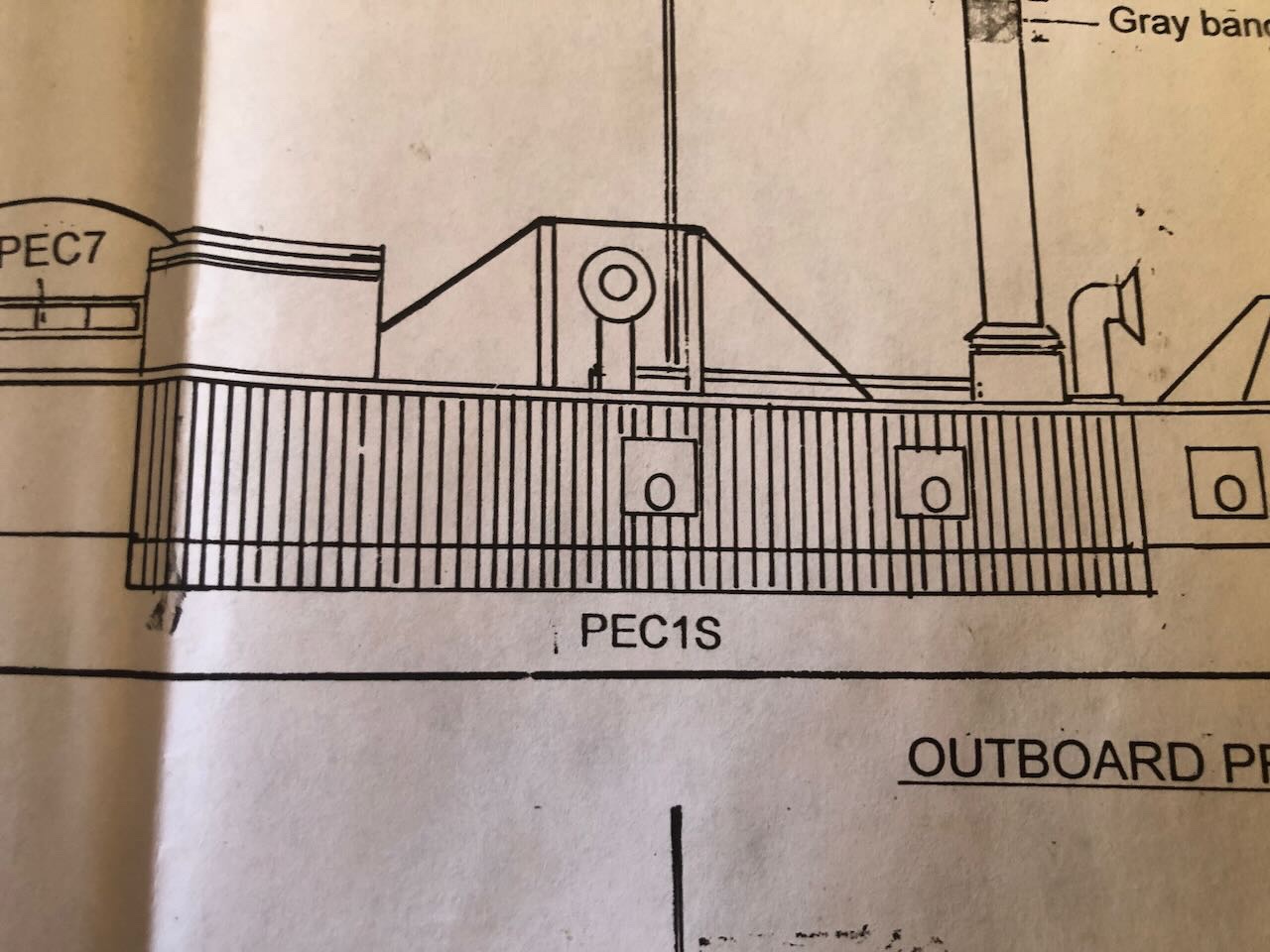
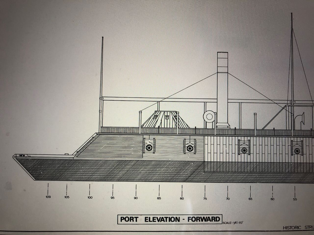
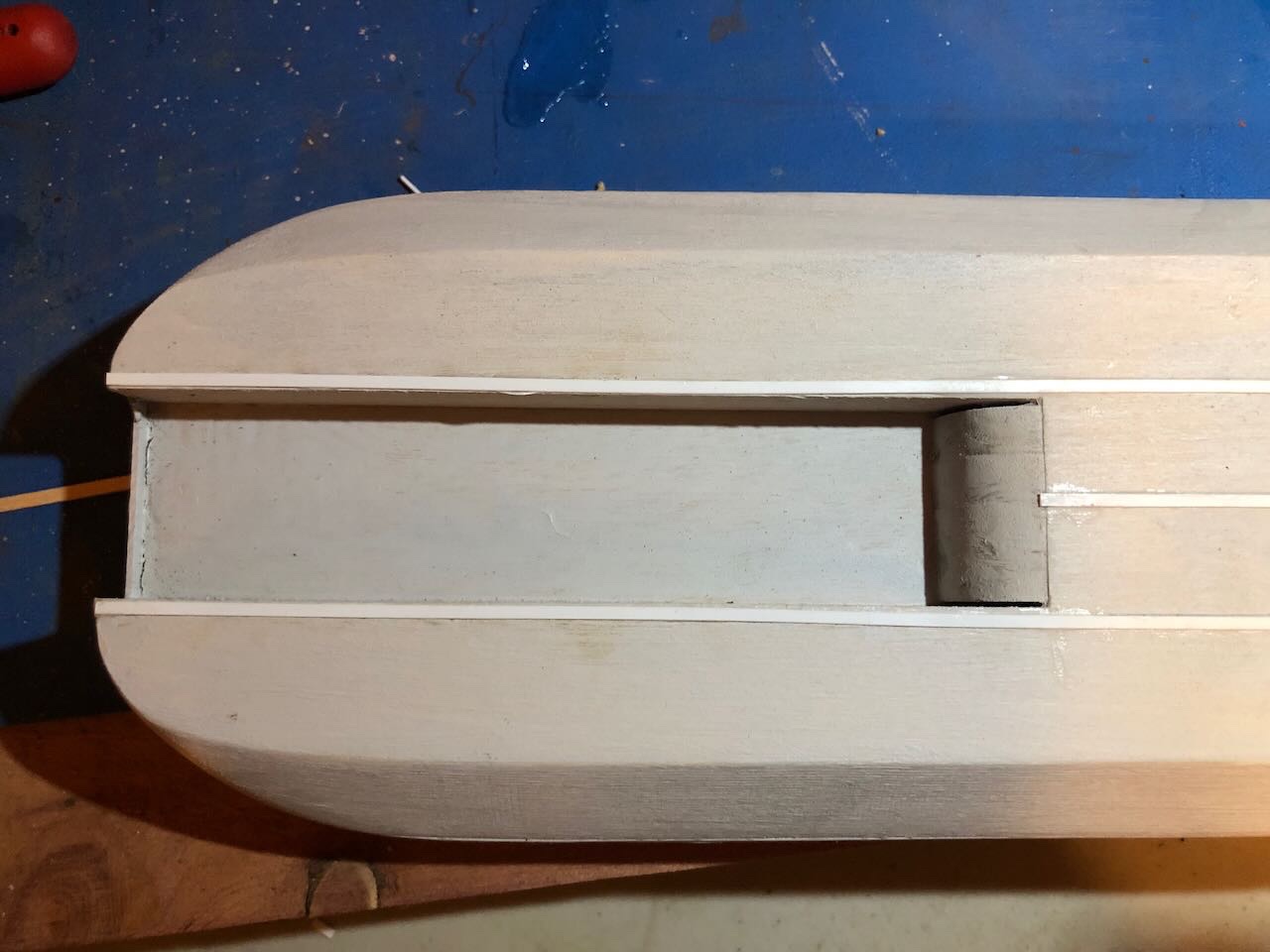
Tried to make further progress this morning and started getting frustrated. The instructions are vague and poorly organized, many parts seem to have a sloppy fit, and it's just not that fun to work on. I can't imagine how this is supposed to be a "beginner" kit. For example, the hurricane deck is far too long for the casement provided. If you line up the bow end with the casement, this is how far it sticks out at the stern end: But this isn't easily fixed, since the deck has a border all around it, and if you just trim the deck to length you'll lose that border and it'll look weird. I tried anyway, and ended up damaging the very thin ply it's made out of, though I was as careful as I could be. I sanded it smooth as best I could. It's still too long, but I don't dare take any more off without ruining the appearance from above. The hurricane deck is also too narrow for the casement provided. There's a clear rim on both sides where the casement doesn't meet the deck. It doesn't seem like it would be hard to machine the casement to a closer dimension in the production end when the shape of the laser-cut deck is already known. Sanding down the casement to eliminate this on both sides would mean removing a LOT of material by hand, and would change the angle of the sides. I'm just going with it. Next frustration was vague instructions on how to place the gunport lids on the armor. All they say is "line up the ovals in the lids with those on the armor". OK, but the lids aren't symmetrical. So which way do they go (test fit shown below): The plans are no help: I consulted the far more detailed plans shared with me by @mbp521, which clarify that the taller end goes up: Next problem, trying to dry-fit the forward and side armor. Neither is even close to the shape/size of the provided casement. The forward armor is too tall and too wide with a noticeably different angle at top: While the side armor is laughably different from the provided casement: These are supposed to fit with a smooth seam between them. The instructions blithely say "trim to fit". OK, how do I do that, I don't have metal-cutting tools. This is supposed to be a beginner's kit. It's one thing to nip metal off thin sprues or file down small nubbins, it's another to cleanly cut an inch of brass without any damage to the piece. @rcmdrvr mentioned using "photo etch shears" when facing the same problem in his log, but I don't have any of those. It never occurred to me I'd need to literally cut the pieces apart to make them fit. I don't think I trust a razor saw to do this without damage. Thoughts?
- 113 replies
-
- 6
-
-
-
- Cairo
- BlueJacket Shipcrafters
- (and 1 more)
-
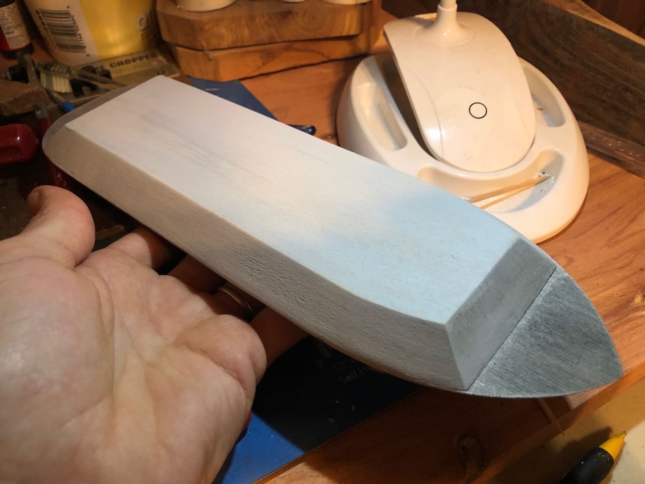
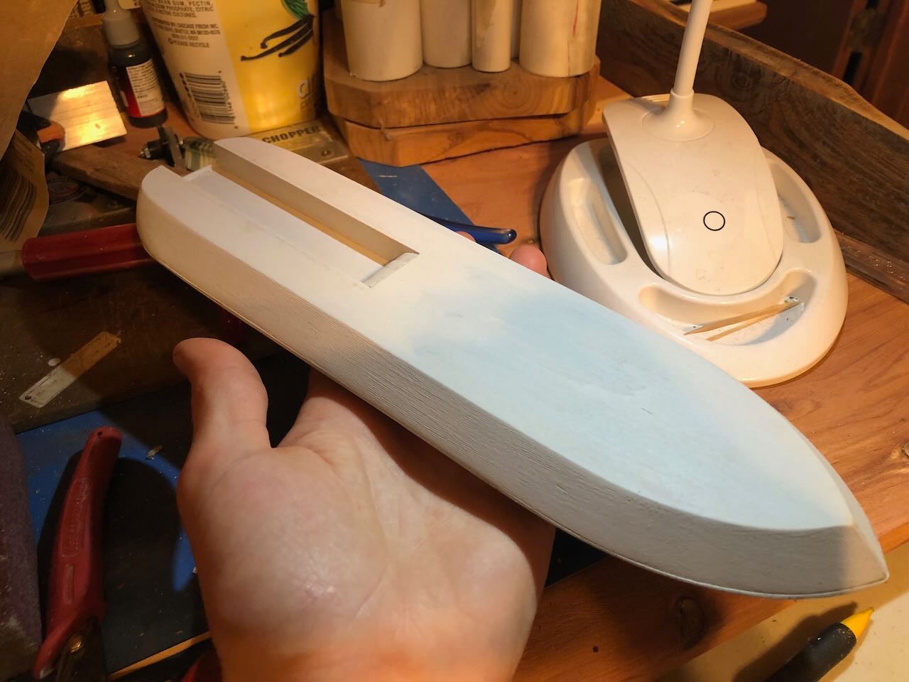
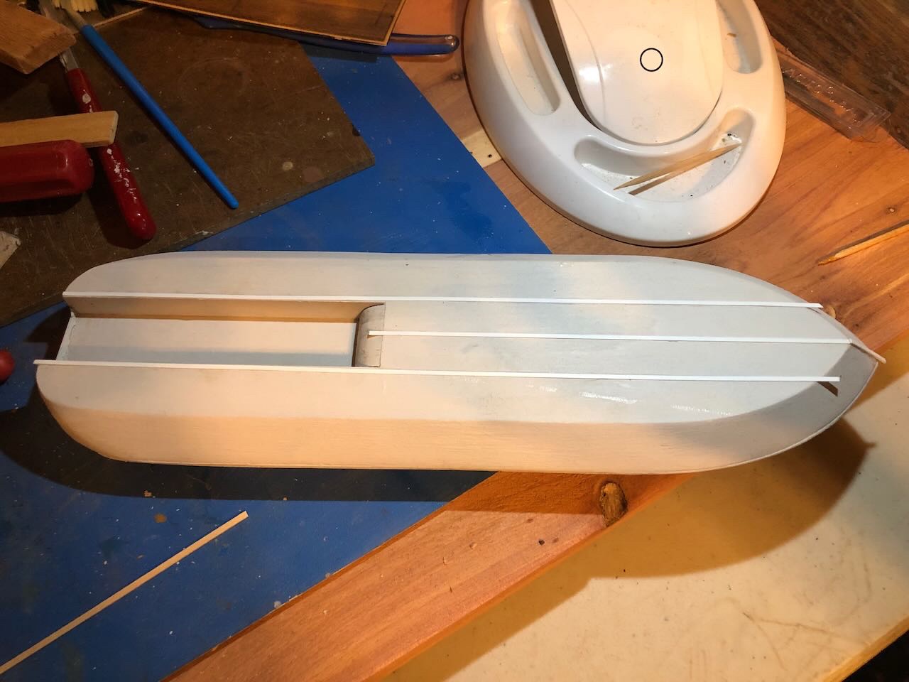
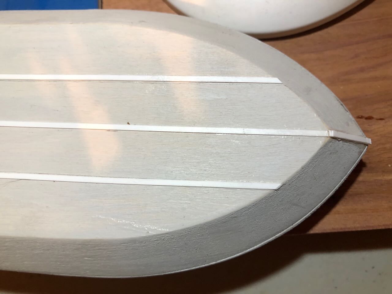
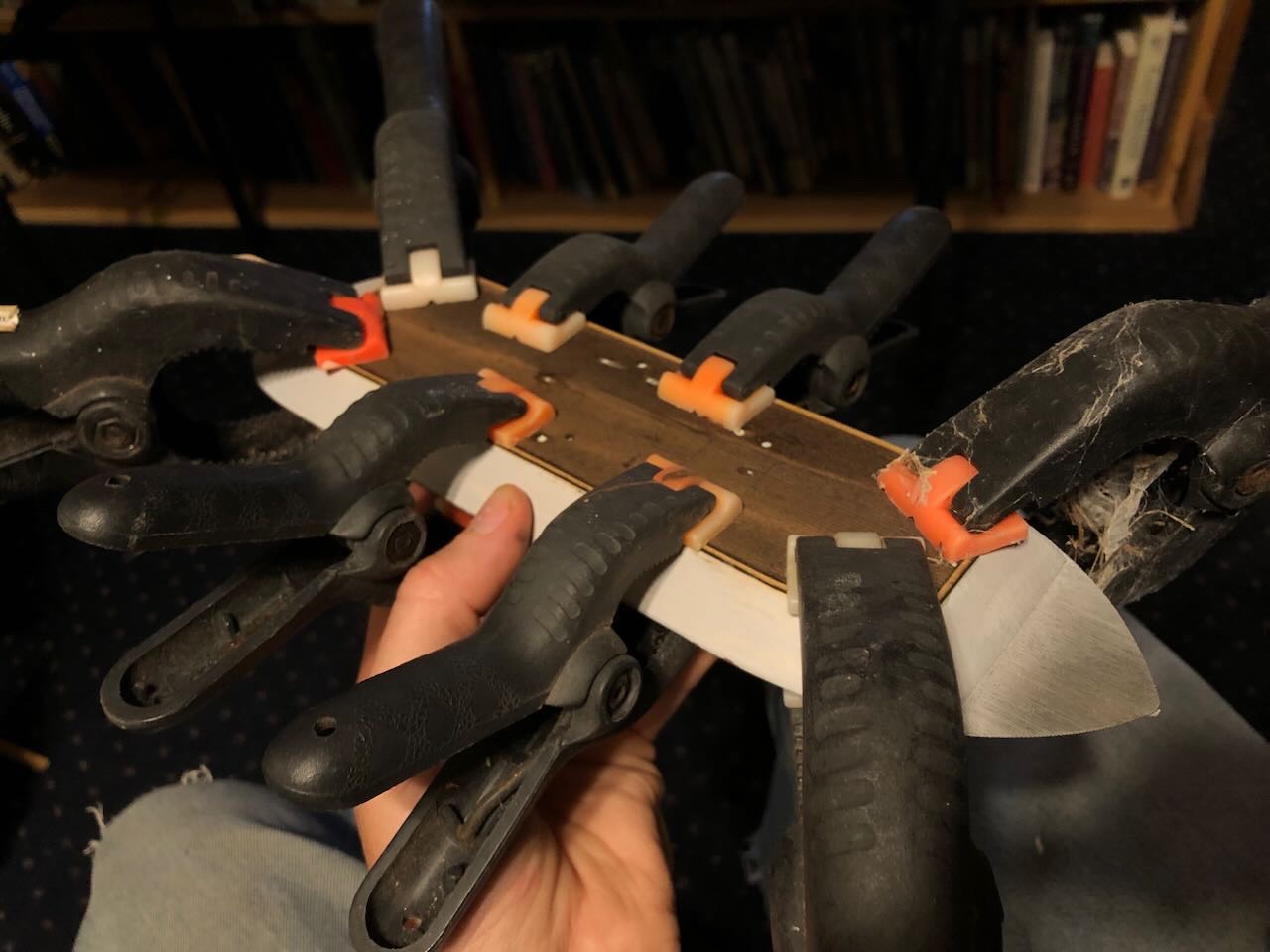
You won't believe this, but I actually got something done on this model! Following the instructions, I primed the hull/casement assembly. I've always used Model Expo paints in the past, I'm used to them and a creature of habit. But I'm out of paint and needed some different colors. This time I switched to ordering some Vallejo primer and colors from MicroMark. I quite like this primer, it's brushable and seems to do a nice job. Here's the first coat: If you're wondering, I gave the deck some primer even though the instructions say to mask it, because I intend to paint it near-white and then weather it down, since I don't like the dark laser burn effect on the scribed decking and I think the decks would have been kept holystoned and pretty bright, not a dull beaten-up color. The next step is to glue some very thin styrene strips to the hull to simulate keels and stem. This is pretty fiddly at this scale, especially trying not to get glue all over the place while a super-thin strip flops everywhere. Think I managed ok. You can see one glue streak that will get sanded off and re-primed. Another coat of primer will help cover some mistakes, and these are on the bottom anyway. Next step in the instructions is to glue on the hurricane deck, so I spread wood glue across the casement top and clamped it solidly in place. Next up is starting to work with the armor. I have next to no experience with etched metal so this will be interesting. Thanks for your patience in this glacially slow build log.
- 113 replies
-
- 10
-
-
- Cairo
- BlueJacket Shipcrafters
- (and 1 more)
-
Honestly, that does have a cool style to it, it looks more authentic than you led us to believe.
-
Try for an angry goose. Anyone who’s been up against one of those will know that berserkers weren’t just Viking legends.
-
Timber-framed outdoor kitchen - Cathead - 1:1 scale
Cathead replied to Cathead's topic in Non-ship/categorised builds
Keith, interesting thought. Initially we were just going to lay some gravel and/or wood mulch there and haven't gotten to it yet, but that was before we made that the butchering area. It's worth considering now that we've shifted operations there, we could dig that out a bit and layer in more gravel. We'll give it some thought. -
Timber-framed outdoor kitchen - Cathead - 1:1 scale
Cathead replied to Cathead's topic in Non-ship/categorised builds
Patrick, it depends on where you live. In general I would guess that much of the US is far more open and rule-free than most of Europe, but there are urban areas that would probably feel very similar to you. And the US is a huge and diverse country that devolves a lot of power to its states, and they do to their counties, so there's a lot of room for variation. I mean, my state of Missouri alone has six times the land area of Belgium and a very wide range of landscapes from rugged mountainous terrain to flat prairies to rolling farmland. Population-wise, we're half the size of Belgium but have counties ranging from a million people to less than two thousand. Hunting permits are regulated at the state level, but vary by county. As far as I know, every state requires some kind of permit, but they're not difficult to acquire. Rules vary widely on how many deer you can take, what kind, etc. depending on local/regional conditions. For example, in some parts of Missouri there are limits on how many deer you can take but in my county there are none (more specifically, unlimited does, still limited to two bucks). Given that I saw twelve of the darned things just yesterday morning, that's good. Also here in Missouri, the first two landowner hunting permits are free and after that they're $7. Which is fine since the funds go to support our very highly regarded Conservation Department. Fees are different if you're not hunting on your own land (we have extensive public lands open to hunting here in Missouri) but they're still affordable and accessible to residents. It's a lot more expensive if you're from out of state, but that's fine with me. As for processing yourself, did you mean it's banned at the national level, or that you can't do it in your specific location? In the US, local regulations might prevent you from processing an animal in certain settings (like the front yard of an urban house) but there's no basic national/state restriction on the right to do so. If anyone tried a rule like that in the rural US it would be universally disdained and ignored. As for the kitchen, again it depends on where you live. In general, the more urban the more restrictive, and the more rural the more permissive. My county does not require permits for structures below a certain footprint, such as this kitchen. Such freedom cuts both ways; it's nice to not go through layers of bureaucracy, but there's also a risk of neighbors doing obnoxious things. For example, in a neighboring rural county with no building rules, someone built a giant horse barn and arena right on their property line very close to another house, and the dust/smell/noise caused major problems for the adjacent house and undermined their property value and resale ability, leading to some nasty lawsuits. No rules works best when everyone's a respectful good neighbor, but it doesn't always work that way. -
Timber-framed outdoor kitchen - Cathead - 1:1 scale
Cathead replied to Cathead's topic in Non-ship/categorised builds
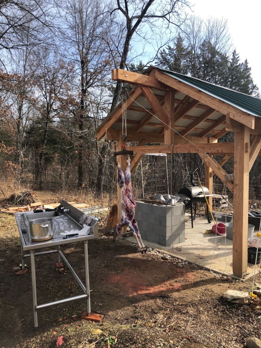
Got deer #2 this morning and achieved proof of concept for the new processing davit added to the kitchen in the last post. Works great to hang just outside the main structure, more room to work and easier to clean up. Still waiting on the right combination of warm weather and sufficient free time to get back to building the grill and oven, but at least the structure is starting to earn its keep.

- 131 replies
-
- 12
-
-
Roger, glad to see progress, I can't complain given my own glacial pace currently. Metal working seems like nuclear physics to me, in awe of those for whom it seems so effortless.
-
I can't help wondering what I wasn't told about a similar-looking piece of athletic equipment...
- 227 replies
-
- 12
-
-