Cathead
-
Posts
3,550 -
Joined
-
Last visited
Content Type
Profiles
Forums
Gallery
Events
Everything posted by Cathead
-

Steamboats and other rivercraft - general discussion
Cathead replied to Cathead's topic in Nautical/Naval History
So I've been given permission to share this image and say the newly found wreck is near Boonville, MO, but I can't give the vessel's name (though they're quite confident they know) or anything else. More info will be coming out eventually but this is image is pretty cool. It was taken with sidescan sonar used to map the river bottom for fish habitat studies, and comes from a former colleague of my wife, who used to be involved in such work. This is also the person who was, behind the scene, instrumental in arranging for me to give this steamboat talk last year. The scientists in question were doing routine scanning work and were startled to see this steamboat framing appear on the river bottom! It's in a relatively protected area, and there appear to be plans to map it more thoroughly in the future. The long axis shown here measures about 40'.
- 281 replies
-
- 6
-

-

-
- Steamboats
- riverboats
- (and 3 more)
-
Steamboats and other rivercraft - general discussion
Cathead replied to Cathead's topic in Nautical/Naval History
One historic steamboat lost, another found I just learned that the historic Mary White II, a steamboat preserved at Jacksonport State Park, in Arkansas, sank in 2016 and is considered unrecoverable. I'd never made it down to see it and we were considering going down there this fall, but obviously hadn't kept up with the news since the loss was new to us. Here's a really nice article from Arkansas State Parks about the vessel, her various brushes with death, and the ultimate loss (read to the very end). https://www.arkansasstateparks.com/articles/mary-woods-no-2-life-river I also just learned from a friend who does research and mapping along the Missouri River that another steamboat wreck has been discovered. They asked me not to share any details yet as several government agencies are involved and they want to do things right, but hopefully soon I'll be able to share some imagery and details. What I have seen is pretty cool. Stay tuned!- 281 replies
-
- 3
-

-
-
- Steamboats
- riverboats
- (and 3 more)
-
New to modeling - wish I found this site earlier
Cathead replied to flutlo6180's topic in New member Introductions
I often do this intentionally, deciding early on which is the test side and which is the display side, and working on the former first so I can iron out any issues before doing the side that will be seen. Welcome to MSW and I hope you have a great time learning and improving! -
Nice progress! An easy way to ensure some extra accuracy would be to rotate all the deadeyes so the triangle of holes faces down; the single hole should be at the bottom with the two holes lined up evenly at the top. This should be mirrored when you add the upper set; two holes facing down and the single hole facing up.
-
This is definitely a good choice for practicing planking. I departed from the instructions in some places where I felt there were other ways to do things; questioning and revising instructions is also a useful skill to have! Good luck and have fun.
-
As a geologist, I offer special congratulations on a lovely use of natural rock! Oh, and the model's pretty nice too.
-
Nice work. You're going to need that mug of beer before you're through! Are there curved sections of railings, too?
- 238 replies
-
- 2
-

-
-
- Robert E Lee
- steamboat
- (and 3 more)
-
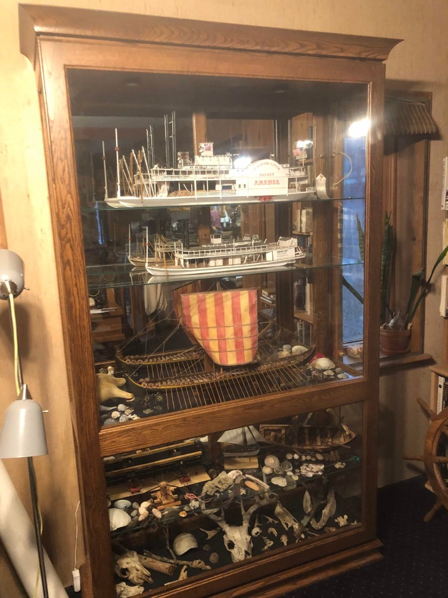
Protection is a near-must, especially for anything with rigging or other delicate details. No matter how controlled your house, dust and spiders and other things are going to accumulate on a model and be nearly impossible to remove without risking damage. There are some places online that sell pretty cheap clear acrylic cases of various sizes; experiment with search terms. Some areas may also have local businesses that work with glass or acrylics and could make you a pretty simple clear display top. It's possible a woodworker or furniture builder could make you a case as well, anyone that frames pictures can, in theory, make a case. Another display/protection option, though initially more expensive, is to purchase a larger multi-model display cabinet, like this one I had made by a Mennonite furniture maker in my area. It now holds three large models and five smaller ones, along with various other items of interest: This has had several major advantages: 1) It's a lot more space-efficient than individual cases for each model; the on-floor footprint isn't much larger than the individual case would be for either of the largest two models but it holds far more. 2) Even though it cost ~$2000, it was far more cost-effective in the long run than acquiring individual cases for each model. 3) It provides all the same protection from dust/damage as individual cases, and indeed is somewhat easier to open and clean as it has a sliding door, rather than having to carefully lift a glass case up and over a delicate model. 4) It's more resellable or transferrable in the long run than individual model cases. If/when I have to move (retirement to a smaller house, say), this could easily be resold to someone with no interest in models but a desire to display any other collectible, whereas model-specific cases have little use other than for their intended model. 5) It's more flexible for display purposes. If I decide to move on from any given model (for example, donating one to a public space or simply deciding it's no longer good enough for display), there is immediately open space for another, whereas to reuse a dedicated single-model case would require sizing the new model for that case. The shelves are adjustable, making this especially practical. 6) It allows balanced display of many interests. For example, note that much of the bottom two shelves is dedicated to natural materials that are of especial interest to my wife, a naturalist. This makes the case an investment for both of us. A spouse who has interests apart from models can share a case like this, perhaps even in an integrated way as we did with the shells and smaller nautical models on one shelf. One can easily imagine ships on some shelves and, say, china or antiques on another in a way that complements both. This one's especially large but they can be had in many different sizes. The key search term here appears to be "curio cabinet"; that will bring up all sorts of online results for premade options and businesses making such things at all sorts of scales.

-
Happy anniversary! Hope you remembered to get her flowers and a card (You make my heart ironclad? Here's to two years of Union?). Your work has me itching so bad to get back to work on another riverboat, but not there yet, so it's great to live vicariously through this (and others).
-
Questions Before I Buy My First Ship
Cathead replied to Magarkus's topic in New member Introductions
Lots of advice already, but mine would be not to overdo it in tools. Most basic-intermediate kits can be built with a pretty reasonable set of simple hand tools. There are experienced modelers with huge workshops and every tool imaginable who will give beginners a giant list of "must-have" tools, but I think @James H has it right. I've built multiple kit and scratch models using what hand tools I could fit on a 30"x48" table in my living room. Fancier tools do make life easier eventually, but they're not needed and may even hinder you from developing good basic skills. There are many skilled "kitchen table" modelers here who do a great job with limited space, so you're in good company! Have fun and enjoy the view. -
Nicely done. I particularly like the deck planking as a personal touch, and it also helps the casual viewer understand the context a bit more. Wish I'd thought of that!
-
I used to do public education for the National Park Service, and I can confirm that as much as I loved it, it was draining to go weeks without meeting a visitor who knew, well, anything.
-
I'm giddy with joy for you, what a fantastic experience! I've been there, but only the standard public access. So grateful you documented and shared your inside scoop. Also thank your wife for the photo including you; I don't know quite why, but attaching a face to online "friends" is particularly meaningful after the past few years.
-
I just stumbled across this after recalling your intro post from a while back. You're doing well so far, learning curve and all. Just had to pop up and say well done to another local/regional builder, there aren't that many of us!
- 65 replies
-
- 2
-
-
- Ballahoo
- Caldercraft
- (and 1 more)
-
I'm so sorry for your loss. Sounds like you're doing a good thing helping the supplies find new homes and helping out the widow.
-
Gluing deck, will this work?
Cathead replied to ubjs's topic in Building, Framing, Planking and plating a ships hull and deck
Glenn, no need to be rude. Certainly the clarification that the original poster is asking about a mostly hidden sub-deck changes the context slightly, since slight errors will be less noticeable and it might well be worth doing it more efficiently. Nothing wrong with the poster trying it and reporting back. This should be a place where we welcome questions, not mock people, even if we don't agree with them. Far too easy to turn people away from the hobby or community that way. -
Gluing deck, will this work?
Cathead replied to ubjs's topic in Building, Framing, Planking and plating a ships hull and deck
Mark, I think the original poster was referring to decking, not hull planking. -
Gluing deck, will this work?
Cathead replied to ubjs's topic in Building, Framing, Planking and plating a ships hull and deck
Like Allen, I'm not clear why you're having difficulty getting glue onto the entire plank? Also, from my experience I'd much rather fit individual pieces in place than try to make a whole assembly fit into place. It's much easier to correct mistakes as you go than all at once at the end. A full-taped-deck approach might work for something simple, but would seem very difficult for a complex vessel with hatchways and other details the planks have to fit around. Seems that you'd spend more time measuring and recreating the work than just doing it once in the first place. And I'd be concerned about even the slightest slippage of planks from the tape, which would leave unsightly gaps or otherwise have things out of place. But if you try it with success, let us know! -
Three points: (1) My understanding is that the Ontario kit is brand-new, which naturally raises its price because the designer and manufacturer have yet to reap any benefits from sales or economy of scale. For example, setting up the casting of any metal parts costs money up front but once manufacturing is flowing it gets ever cheaper to reproduce those castings. Eventually the price will come down as the initial investment is paid off. Also, I believe that kit used a bunch of fairly new/innovative 3D design techniques to produce some of the trickier parts, which raises the potential quality of the kit but also its price, compared with an older kit using poorly cast metal and/or just providing you with raw materials to make the part yourself (think detailed windows). Finally, if it's made in Europe, it's probably especially expensive to ship over to the US right now given how messed up shipping and supply chains are. (2) As others have said, use sensible buying practices. I just looked, and this kit is currently marked down to $699 from $969 on Model Expo. So you just "saved" ~$270 by looking again. (3) A touchy point for me is people complaining about the price of kits (this is not aimed at the original poster here, but a more general comment). Designing and producing kits is a very time- and labor-intensive process, and kit-makers are businesses that have to earn a living. Cheap kits are generally cheap for a reason; either they're low-quality or they've been around long enough that their makers have long since recouped initial costs (and this often means their quality and design is out of date, as is the case for some Model Shipways kits). Or in a few cases they're pseudo-kits that expect you to do a lot more scratch work than the average kit, thus keeping costs down (e.g., Syren). There's no inherent "right" to afford whatever model kit you want. We aren't all made of money (I certainly watch my budget) but a good life lesson is that sometimes we can't afford things we want, or need to make hard choices to get things we want. Personally, even $1000 works out to a pretty good return on investment for something that would take the average people a couple years to build; that's ~$50-$100 a month, the price of cable TV and with far less toxic effects no matter what glue you use! EDIT: Meant to add, for anyone interested in the Ontario, check out the book Legend of the Lake, which tells her story in good detail with extensive drawings, along with images of the wreck and the story of its discovery.
-
Looks fantastic! How are you going to display the model?
-
Really cool! Love the multi-part display; I have a somewhat similar thing with a few Model Shipways naval cannons and my scaled-down NRG capstan. Really adds visual interest to present things like that together. And yours are all so crisp and eye-catching.
-
Looks great, and matches my experience with it being a good product.
-
Just a thought, many users are on slow internet connections. With my rural American internet, posts with lots of large photo files load slowly and awkwardly, and can really undercut the user experience. I suspect the same is true in many countries. Unless you're trying to show very clear detail, users might consider keeping basic photos relatively small (in terms of file size) to increase the site's accessibility for all users.