
HOLIDAY DONATION DRIVE - SUPPORT MSW - DO YOUR PART TO KEEP THIS GREAT FORUM GOING! (83 donations so far out of 49,000 members - C'mon guys!)
×


Cathead
-
Posts
3,503 -
Joined
-
Last visited
Content Type
Profiles
Forums
Gallery
Events
Everything posted by Cathead
-

Chaperon by joep4567 - 1:48 - Sternwheeler
Cathead replied to joep4567's topic in - Build logs for subjects built 1801 - 1850
Nice work! -
Yes, the clamps are made by combining multiple pieces. It's 2 for 3, as you take the two arms out of one and each arm gets inserted in another clip. The "tubing" was just how some of them came, I have both types and don't think it matters. I keep the original pieces so I can always put them back together the normal way if desired. I have various types; sometimes it works well to insert an arm from a larger type into a clip from a smaller type, but you can experiment with what works best for you. Also, if you haven't run across this idea yet, inverting normal clothespins makes them much more useful. Those are also shown in the image above. You basically flip the two halves over within the spring, giving a smooth clamping surface. This also makes the grip a LOT stronger. I have a bunch of these and use them all the time.
-
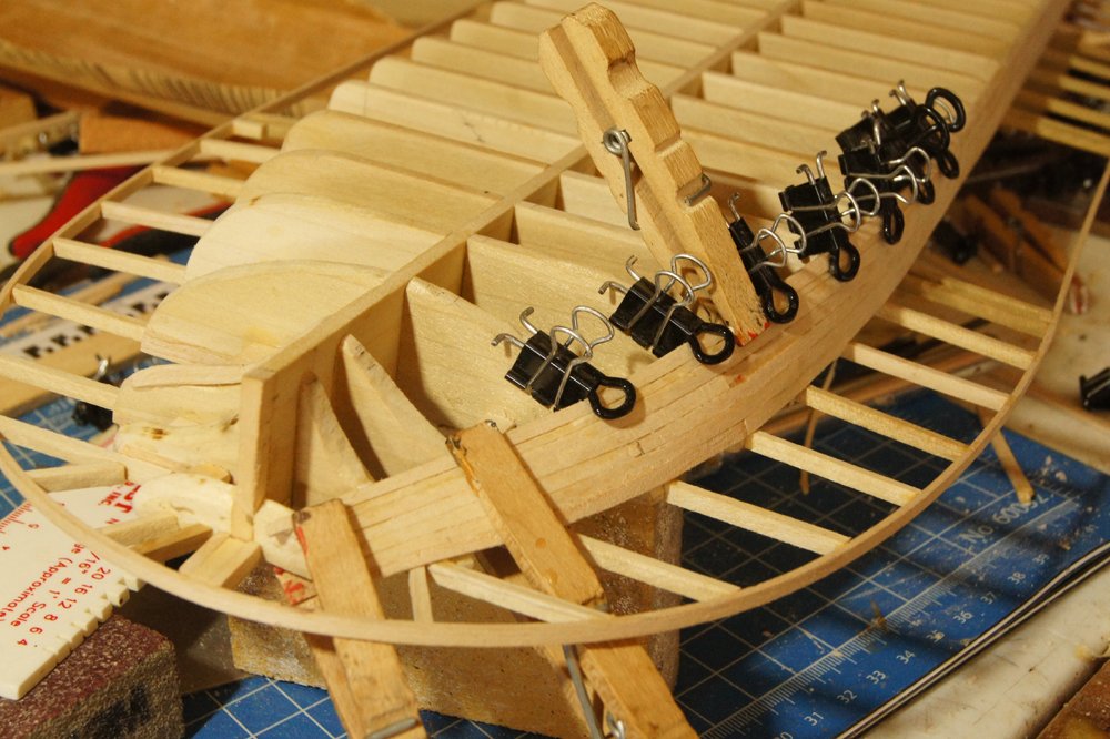
Looks good. My normal procedure (everyone has a different one) is to use warm water, as I've read that the heat helps loosen the wood fibers. I think it partially depends on the thickness of the plank. What kind of clamps are you using? The sort of three-dimensional geometry that's needed to hold a plank to a frame is pretty complicated. Here's one of my favorite styles (not my original design), made by adapting standard office-supply binder clips. These are great because they hold really solidly to the frame/bulkhead, but don't directly clamp onto the wet plank, minimizing the chances of deformity (photo from my last build): Obviously I'm also using more typical clamps here as well, but in this case I'd tested and found that I wasn't getting too much plank compression.
-
Chaperon by joep4567 - 1:48 - Sternwheeler
Cathead replied to joep4567's topic in - Build logs for subjects built 1801 - 1850
When building paddlewheels from scratch, I've found it surprisingly difficult to get them all perfectly the same, and even tiny variations will ripple throughout the wheel once you try to line up all the spokes with straight buckets (the horizontal planks that tie the spokes together). It can help to define your first wheel as the pattern, then build each subsequent one directly on top, using clamps or pins to guarantee that they match. It also helps to clearly mark one spoke as the starting point for when you try to line them up later. Again, even tiny variations in the pattern will cause problems later, so knowing which is spoke A on each ring is really helpful, as is which way it should be oriented (mark the starboard or port side of each ring). Otherwise you can end up rotating them around like tumblers in a lock, trying to find the right combination. -
Just read through this build, great work. Love some of the extra details like the anchor, I may use that for my current build.
-
Nice problem solving so far, glad to hear you're enjoying your first build! If possible, I'd strongly suggest experimenting with plank bending on any similar scrap material you may possibly have around, just to get a physical sense of how it works and feels. Many skills in wooden model building end up being tactile as much as intellectual, in my opinion, and there's nothing like feeling how something works before you do it for real. One note when using water/soaking to bend planks: wet planks are compressible and can receive damage while drying (such as from an overly tight clamp). It's so frustrating to bend a wet plank, then find out later it has a big clamp divot in it. This is especially true for open boats like this where the planks can be seen from both sides (at least the upper ones). This is another case where experimentation with scrap will help you figure out what you can and can't get away with. I'm not familiar with this model, but from the page you showed, it looks like the planks are pre-spiled? Meaning that they aren't straight strips but are pre-cut in a curve that will help them take the shape of the hull? If so, that eases your job considerably. Planks that come with bundles of straight strips mean a lot more difficult bending work. On the other hand, pre-spiled planks make it all the more important to practice your methods first since you only have one shot at each plank. Great start and I can't wait to see where you go with this.
-
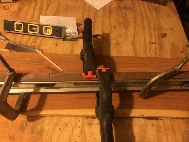
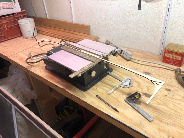
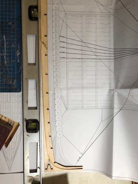
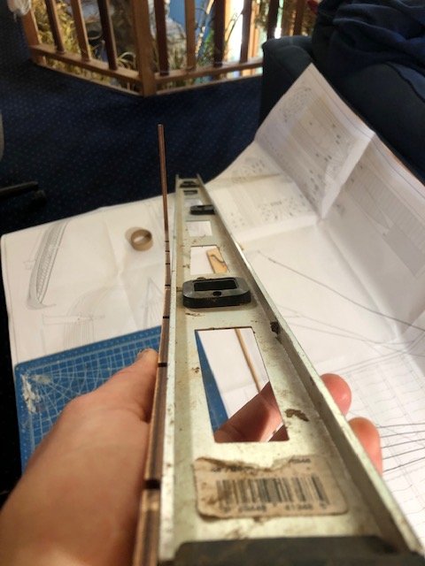
I did indeed soak the keel, then laid the two pieces out on my garage floor (a known smooth, flat surface) and weighted them down with a set of bricks. 24 hours later, the pieces were much straighter. I then stained them using a Model Shipways walnut stain that I bought for this project, then attached the two halves using clamps and an extra reinforcing strip of scrap wood. I laid the whole keel onto a 4' straightedge/level for this, which allowed me to clamp them into place perfectly straight while the glue dried (joint is under the two black clamps in the image below): I then set about figuring out how to construct a proper build frame using scrap wood available in my shop (which is mostly rough-milled Eastern Red Cedar from lumber I harvested). Here's what I came up with, following the examples shown above: This is very sturdy and holds the fragile stem and stern solidly in place. The whole thing was screwed together, as I hate using glue on things that won't be permanent as then I can't burn or naturally dispose of the wood scraps. Now I can take it all apart again when I'm done. The thin strips holding the central part of the keel in place are partially cedar and partially some random leftover wood from my scrapbox, no idea what it is. If you look closely, you can see that I did use curved portions of the original laser-cut sheet to support the stem and stern; I just cut off the long extensions under the central part of the keel so I wouldn't have to worry about the whole thing being straight. This worked great. Here's a detail of the jig I built for attaching frames, again based on examples from other build logs (especially jack.aubrey's): I used a Byrnes table saw to ensure that everything was completely square. The series of horizontal lines drawn on the surface allow the frames to be lined up at various heights. The "feet" allow this to be clamped in place on the build board anywhere I want, following lines drawn onto the board using a square. I think it'll work well, and can adapt it if I find a flaw. It's all rough, but seems like it'll do the trick. Time to stain the frames and then start assembling things.
-
I think we all feel that way when a hull is nearing completion. To my eyes you've done a nice job, we're always our own worst critics. I get better with every model.
-
Chaperon by joep4567 - 1:48 - Sternwheeler
Cathead replied to joep4567's topic in - Build logs for subjects built 1801 - 1850
I thought you said you had purchased plans, wouldn't that be part of the plans? I don't have plans, but there are a lot of Chaperon builders here who will find your log soon and help you out. -
Chaperon by joep4567 - 1:48 - Sternwheeler
Cathead replied to joep4567's topic in - Build logs for subjects built 1801 - 1850
There's a good argument for not planking the bottom, which can't really be seen. Are you going to plank the sides, which are visible, or are you figuring that paint and the low viewing angle will obscure the wood grain and joints? Certainly, it may not matter if your goal is a representation in a certain style rather than an accurate scale model. Interested to see where you take this idea. -
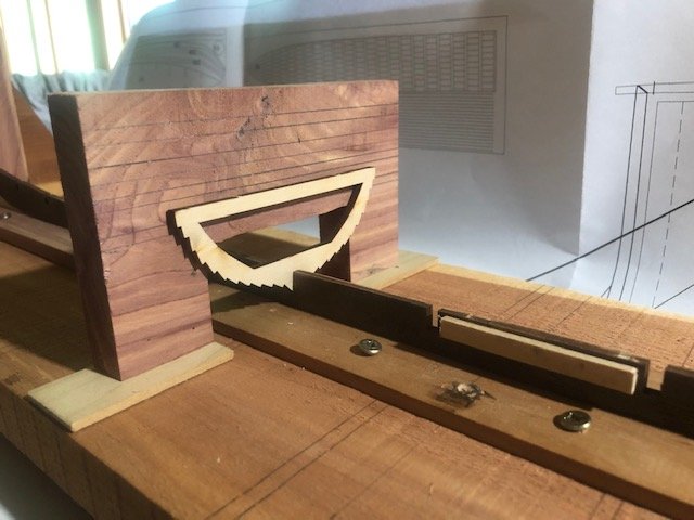
It's been another really stressful week and I'm feeling very run down, but I finally got started on the model this weekend, and immediately ran into a couple barriers. First, as has been reported in other logs, the keel pieces are a bit warped. I'm trying to decide whether I need to soak and weight these, or whether the use of a proper building board and frame will be sufficient to hold these straight until the planking holds them in shape. What do you all think? Second, I'd like to adapt the style of building frame used by jack.aubrey and seventynet as shown below, respectively: The basic issue is that, unlike many "modern" vessels, the bottom of the keel has almost no flat surface and thus very little reference point to start from. It carries a smooth and subtle curve pretty much all the way through. I thought I had a good idea by thinking that I could adapt the original wood sheet from which the keel pieces were laser cut, since these carry the exact curve of the keel. If I cut those in a way that gave a smooth bottom, I could simply use that to support the keel! The immediate problem was that these did not have the same depth of wood below the keel for each piece, so I had to trim them. I carefully set a table saw to trim the thicker piece to match the thinner piece, assuming that I could then lay both flat and simply set the keel into them: I'm a fool. The fact that the keel has a constant curve means there was no reason to assume that a given straight line would follow all the way through or that the bottom of the original wood sheet had any relevance to the orientation of the keel. So this was what I got for my trouble: Time to start over and come up with a different solution. What I should have done is tape the keel pieces together, tape the two pieces of outer wood below them, then use the straightedge to draw one consistent line across both that I then cut using the table saw. Somehow didn't see that until it was too late. Which takes me back to whether I need to soak & weight those keels or just build a good frame. The warps don't seem too bad, but I haven't built something like this before so don't know what to expect. So much for this being a relaxing build that just lets me follow instructions!
-
I have never done what you're trying but my personal instinct would be to use more layers initially to minimize the amount of shaping later. This lowers the risk of difficult-to-repair mistakes in shaping, whereas you can always recreate an initial cut if you don't like how it came out. But again, this is not based on actual experience. I supposed you could try shaping the layers before gluing by clamping everything together really well, but it could be difficult to recreate the exact configuration when gluing. You're on your own here, I think.
-
Out of curiousity, what was your reasoning behind waiting to stain the hull until after assembly, rather than staining each plank separately ahead of time? I would have thought that staining after assembly would risk messing with the glue? Apologies if I missed this answer earlier in the log, I'm reading lots of stuff right now in preparation for my own build and may have overlooked it.
-
For those interested, I have now launched the Viking longboat project. The Missouri River photo shoot is still a goal, but life has intervened in a serious way and I will get to it when I can.
- 599 replies
-
- 3
-

-
- sidewheeler
- arabia
- (and 4 more)
-
Just discovered this thanks to the welcome reorganization of MSW by era. Glorious work, so sorry I wasn't in from the beginning! Love the oarsmen, wondering if I'd have the patience to make some Viking rowers the same way.
-
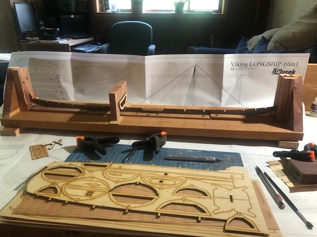
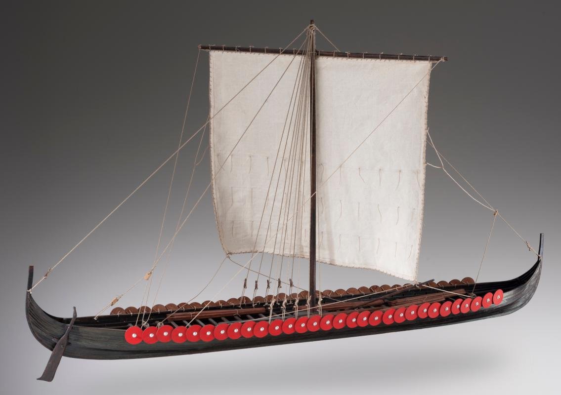
After a long and complex scratchbuild (the American Missouri River steamboat Arabia), I felt the need for something a little more relaxing (i.e., with instructions and someone else's planning work). Being of primarily Norwegian/British/Irish descent, I've long been interested in the Anglo-Saxon-Viking era and a ship from that period makes a very distinct project from my core interest in American riverboats. So I settled on this Dusek longship, based on one of the five vessels found at Skuldelev in Denmark. The fact that the original was built in Ireland adds extra interest for me, and I've read good things about Dusek kits. From the Dusek site: Dusek makes kits for three styles of Viking ship: this longship, the Gokstad ship, and a knarr. All three are offered in 1:72 and 1:35; I chose the latter as I was interested in the chance to include some extra detail possible at this scale. As far as I can tell, there isn't a single build log for this kit on MSW, so hopefully this is of use to others. Here are all the logs for Dusek Viking ships that I could find on MSW (please alert me if I've missed one): Gokstad Viking Ship by jack.aubrey - Dusek Ship Kits - 1:35 Scale Gokstad Viking Ship by Seventynet - Dusek Ship Kits - FINISHED - 1:35 Scale Gokstad Viking Ship by Dr PS - Paul Schulze - Dusek Ship Kits - 1:35 Scale Viking Knarr by Daryl - FINISHED - Dusek - Scale 1:72 Viking Longship by Binho - Dusek - Scale 1:72 I don't intend to build this as an exact replica of the original but rather use it as a base to adapt the vessel to have certain features I find interesting. For example, I've done some reading on various ways shields were hung/displayed and want to modify this to use a shield rack (as was found on a different Skuldelev ship). I'm also going to replace some of the kit wood with material harvested and milled by myself. There are other possibilities I'm toying with that may come up in good time. I haven't started on the kit yet, but wanted to announce the build and welcome anyone who's interested in these vessels to follow and offer me advice as I take on something very different from my normal milieu.
-
Any further progress on this build? I'm about to start a similar kit and would love to read about how yours is progressing.
-
Virtual 3D Steamboat Tour & other info (Chaperon)
Cathead replied to RussR's topic in Wood ship model kits
An extra-nice detail: in the "Ladies Cabin" location on the boiler deck (go inside the main cabin and head toward the stern), there's an 1845 painting of fur traders on the Missouri River by Missouri artist George Caleb Bingham on the wall. A slightly odd choice as Chaperon was an Ohio River boat in a much later era, but as I love Bingham's work documenting scenes of American western rivers during the early steamboat period, it was really cool to see this one hanging there. -
Virtual 3D Steamboat Tour & other info (Chaperon)
Cathead replied to RussR's topic in Wood ship model kits
That is really wild! Thanks for sharing. -
Just catching up after spending a few stressful weeks dealing with an in-law crisis. Your work looks great and I empathize with trying to get a detail right that you know isn't quite how you want it.
-
Sorry for the late reply, I've been away for a few weeks dealing with a major crisis with my in-laws. I'm no expert, but I believe hull planking was commonly ~20-30' long, bourne out by various comments on this thread: https://modelshipworld.com/topic/14226-questions-about-plank-lengths/ EDIT: Also found this nice story in American Scientist magazine about the Beagle, might of interest to you.
-
Congratulations on finishing! Always a good feeling.
- 23 replies
-
- 2
-
-
- model shipways
- chaperon
- (and 1 more)
-
Thanks so much for updating this! Missed hearing from you. Lovely work.
- 48 replies
-
- 3
-
-
- queen anne barge
- Syren Ship Model Company
- (and 1 more)