Cathead
-
Posts
3,523 -
Joined
-
Last visited
Content Type
Profiles
Forums
Gallery
Events
Everything posted by Cathead
-
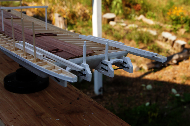
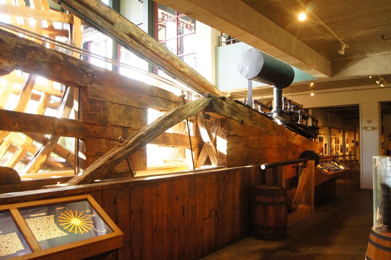
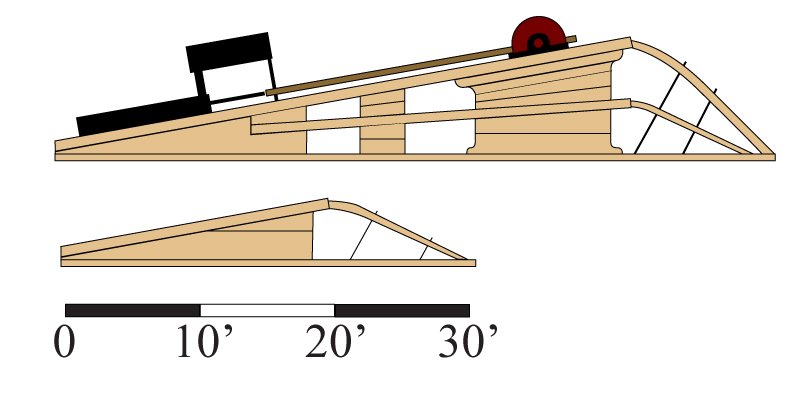
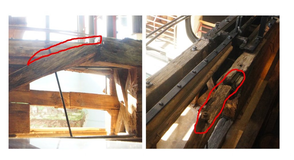
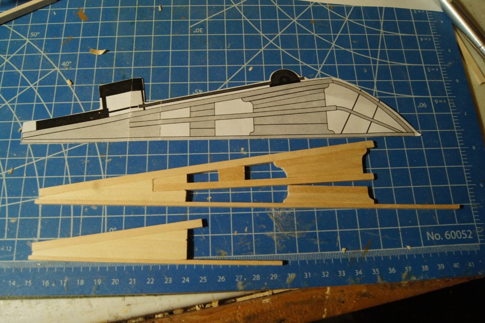
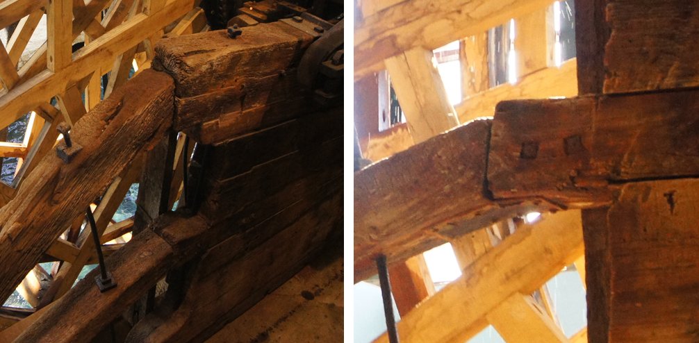
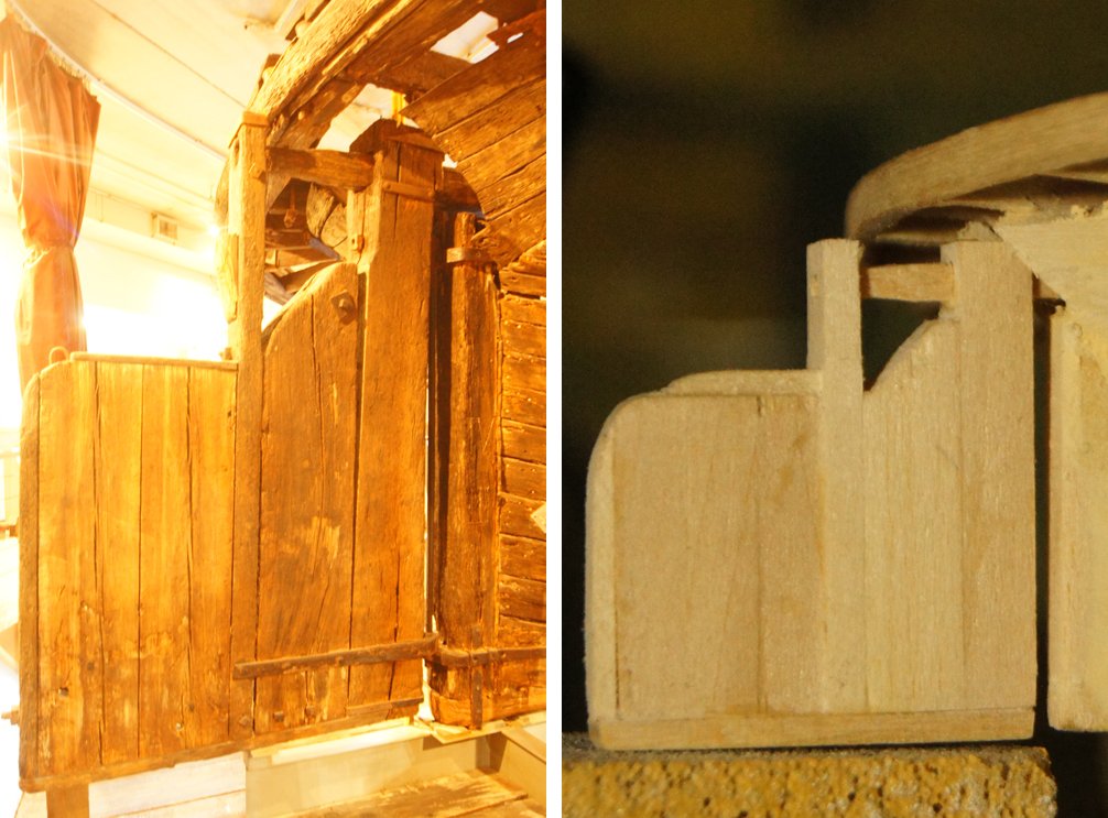
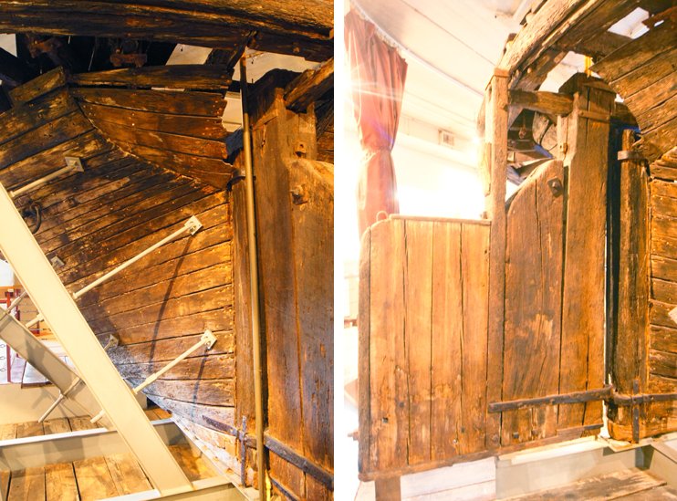
 I'm now working on the cylinder timbers, the pair of large timber frameworks that support the piston engine and paddle wheel on each side of the boat. A full original set is on display at the museum. although the tight quarters and large size made it very difficult to photograph the entire assembly in one view: Thus, for reference, here's the drawing I made of these based on measurements and photos taken at the museum. I've printed these out at scale and used them as a template for the model: Each set of cylinder timbers consists of a larger assembly that extends to support the wheel, and a smaller assembly that supports the other side of the piston engine but is much shorter. Here's a view from the engine end, looking toward the stern. The (port) wheel is on the view's right, so the assembly to the right is the big one, while the one to the left is the smaller one that only supports the engine. I hope that's clear. And here's what I've built so far. I started by carefully cutting the thickest angled piece under the engine and using that to define where each of the larger beams went. From there, I'm slowly filling in the shorter support blocks. I'm building both sets of timber assemblies at the same time to ensure that they match, even though it really doesn't matter since they don't connect across the boat in any way. I just think it's helping me make them correctly to do it together (and reduces the redundant feel of starting over on the second one after finishing the first). Current status of one set (the other looks the same) next to a template: I've now run into an interesting problem that I hadn't noticed before. Both the large and small sides have wooden braces at the stern end that angle down from the thick cylinder timber to act as a counter-brace (these are on the right side of the drawings posted above). On the large assembly, they simply butt up against the timber end with a metal bracket connecting the two, and what looks like a simple mortise on the lower one: But on the short assembly, there's a strange quirk about the connection between the timber and the brace: In the image above, notice how the brace (on the left) meets the timber (right) well below the latter's top surface. Moreover, the large vertical bolt that ties all this together is too long by maybe 4-6", what looks like about the same gap (outlined in red). And from above, you can see that there's a notch in the timber. So was there some kind of extra wooden brace that extended from a notch in the timber, over the top of the brace, different from how the other two worked? I don't know if that explanation and question is clear; I'm sure I suffer from the curse of knowledge from studying this so much. But if that makes sense, does anyone have any ideas? I can't see any evidence for how such a brace would have been shaped if it had existed, and am somewhat reluctant to add something that isn't there in the recovered assembly. But it seems strange to me and I'm just curious about thoughts on this very esoteric question. Working on these has been a nice change from planking; I'm glad I tackled this next. Thanks for reading.
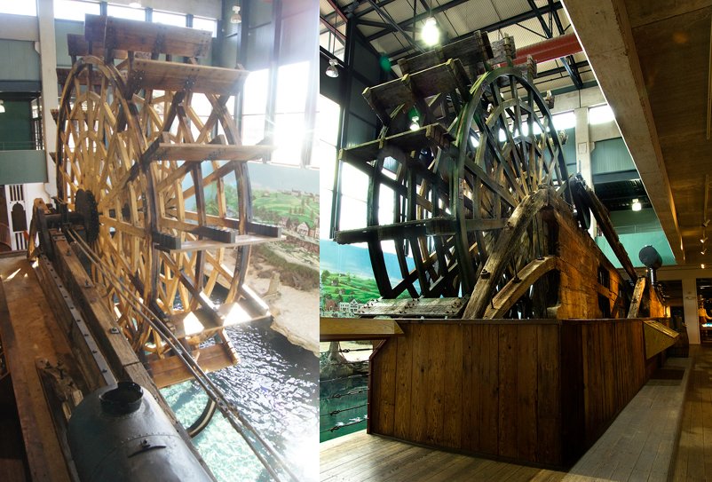
- 599 replies
-
- 10
-

-
- sidewheeler
- arabia
- (and 4 more)
-
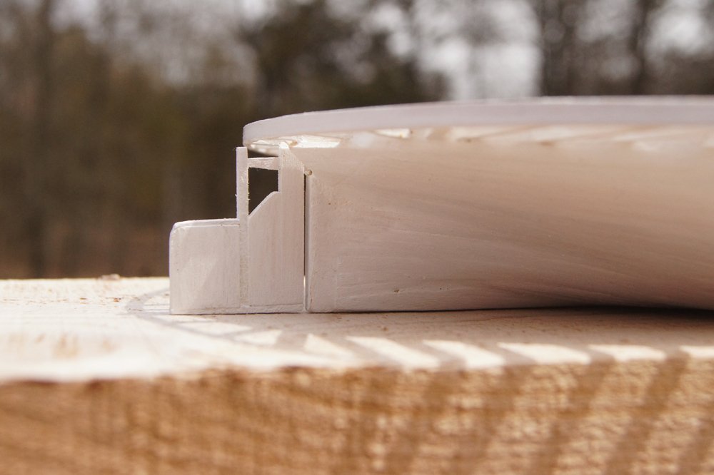
The hull is finished! After sanding to an acceptable texture, I primed and painted it using Model Shipways primer and white, thinned and with several coats. This sealed off any remaining tiny gaps nicely but the planking can still be seen. I rebuilt the rudder to get proportions I found more pleasing, and painted that too. It won't actually be installed until much later, but it's done. And two more views of the hull from bow and stern: I had intended to plank the main deck next, but changed my mind. I'm going to build the cylinder timbers and wheel supports next, because those will inform how I lay out the deck and superstructure. Plus, I've dealt with enough planking for now. Thanks for reading!
- 599 replies
-
- 15
-
-
- sidewheeler
- arabia
- (and 4 more)
-
I'm self-employed; there's no such thing as sick leave. Enjoy it while you got it! Nice work on the guns.
-
With regards to the last few planks where clamps will no longer reach the bulkheads: this is where the old advice to ensure that each plank is pre-bent to fit really comes into play. I'm no pro, but what has worked very well for me on multiple models is to soak the given plank and hold it in place with my fingers while using a hair-dryer to quickly "set" its shape. This may take several rounds, but the dryer works quickly enough that clamps aren't really necessary. Once the plank is bent to its shape, any final shaping can be done, then it can be set in place with glue and held in with fingers. Even basic wood glue will set within a couple minutes under finger pressure, meaning you don't really need clamps if you've done the work ahead of time to ensure that the plank isn't trying to spring out of its slot. You can also try laying a loose piece of wood across the plank and fitting a rubber band or other strap around the hull to hold that loose piece down as a sort of "floating clamp". A thicker block can help if the band is held away from the hull by the keel or other protrusion. And the thicker it is, the more pressure is on the plank as the band stretches around it.
- 53 replies
-
- 3
-
-
- rattlesnake
- model shipways
- (and 1 more)
-
size of people
Cathead replied to Snow's topic in Discussion for a Ship's Deck Furniture, Guns, boats and other Fittings
And even Normal Rockwell painted selfies.. -
You should be proud to display her. I particularly like how the sails came out.
-
You're definitely right that the proportions of this kit are out of whack. The figures will add a really nice touch, though.
-
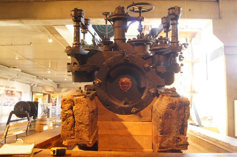
Thanks, Bob. Though, actually, compared to building every single full-hull frame from scratch for Bertrand, this has been a relative breeze. I do agree that having the real thing for comparison is both exciting and daunting. I'm slightly dreading the machinery for that very reason, as (a) machinery is not really my strong point and (b) having the real machinery on display in a museum makes the standard for accuracy awfully high. There are some interesting questions there that I'll get to once the deck is planked.
- 599 replies
-
- 6
-
-
- sidewheeler
- arabia
- (and 4 more)
-
I've made slow progress on some unphotogenic work, mainly filling in the myriad little gaps in planking between every deck beam extending out to support the guards. This took forever, as each little piece had to be cut and filed to shape given the odd angles of the hull, particularly at bow and stern. They're not all quite straight or perfect, but some judicious wood filler and filing took care of that, and they'll be almost invisible on the finished model once the decking is installed and they're tucked in the shadows under the guards. I didn't bother to take a photo of this as it really isn't very interesting. It took a long time, but a couple interesting soccer games over the weekend helped me keep plugging away. Beforehand, now that the hull was planked, I made a basic support jig that allowed the hull to be clamped into my handy rotating work stand: Unlike a sailing ship, these riverboats had little to no external keel, so there's nowhere to attach such a work stand to. I really like having my models on a rotating stand like this, because it allows me to choose the right angle for any given job and often makes the work a lot more ergonomic. Thus I made and screwed this into the hull; it's nice and solid. Although this setup is rough and ugly, I measured the screw holes in the hull to be exactly where I'd want them for the final display stand. So I'll be able to mount this properly once the work is done. It already made filling all the planking gaps much easier because I could tilt the model as-needed to see each gap. Also, as there were questions about the rudder, here's my rudder next to the original: Now that they're truly side by side, it seems that I got a few proportions slightly off. Some of this can be solved by a bit more sanding. I may end up redoing this, using the photo pair above as a better guide. I won't attach this until near the end of the project, so it's not of immediate concern. It is neat to compare the model and original side by side like this, I'll try to do a few more photos. Next up, I'll take the jig back off the hull and do a final sanding. Once I'm happy with it surface, I'll go ahead and paint it. Then it's on to deck planking. Thanks for reading.
- 599 replies
-
- 12
-
-
- sidewheeler
- arabia
- (and 4 more)
-
One Corel kit was enough. Terrible instructions, shoddy materials, inaccurate design.
-
Noted Riverboat Modeler Glenn Hensley has passed away
Cathead replied to kurtvd19's topic in Nautical/Naval History
Thanks for sharing this, Kurt. I appreciated the change to read about Mr. Hensley, his life, and his models. I've never been to this library, but it sounds a very worthwhile visit. We've been trying to find time to take an overnight trip to St. Louis, so this will certainly add to the list. -
Of course, Mike! You're already a steamboat veteran given your excellent Chaperon.
- 599 replies
-
- 4
-
-
- sidewheeler
- arabia
- (and 4 more)
-
At the rate you people are starting build logs for this kit, I'm about ready to figure out how to design and offer another riverboat kit to give more options given the apparent interest.
-
Yeah, I'm drooling. Thanks so much for taking the extra time to share this process with us. I'll certainly pay you back when this hits the market.
-
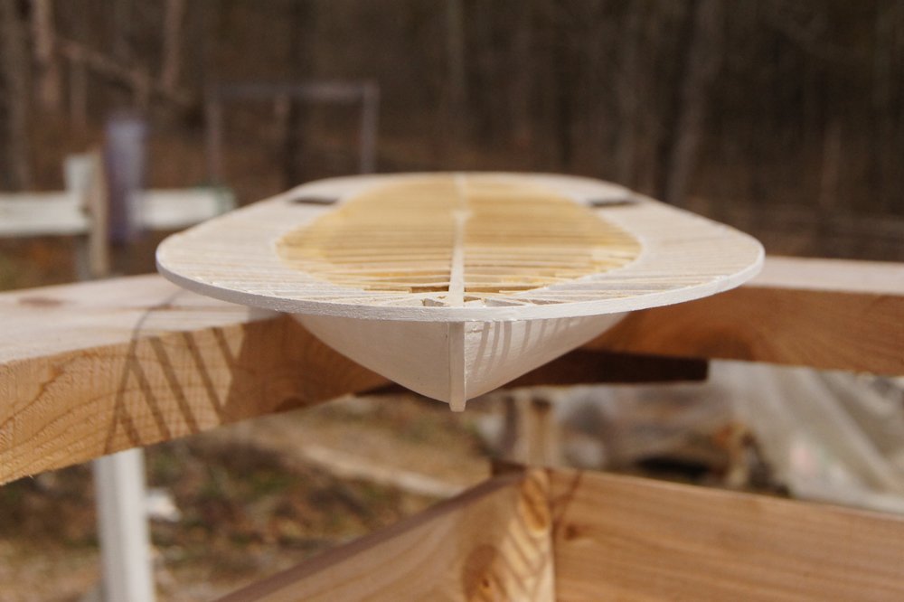
Good question. Yes, sidewheelers generally had one center rudder, because their hulls were more ship-like (tapering at the stern) so water flowed properly past a single rudder; they were also more maneuverable due to the ability to back each engine separately. Sternwheelers commonly had two to four rudders, often linked into a single system. My understanding is that their more barge-like square sterns didn't funnel water past rudders as efficiently, so they needed more rudders spaced across the stern to compensate. For example, here are the rudders on my model of Bertrand: These were built in two paired assemblies; the inner two were connected to the actual steering gear, and the outer two were slaved to their partners. Also note that each rudder fits into an extension that runs forward into the curve of the hull; my understanding is that this helped direct water properly onto each rudder. The hull was shaped this way on sternwheelers (wide and square like a barge rather than tapered like a ship) because that design provided the extra buoyancy needed to support the massive, heavy sternwheel. In comparison, here is the salvaged stern of the Arabia: Note how the hull naturally tapers to the single rudder, which it can do because the wheels and engines are placed much more forward on a sidewheeler, so the stern can be shaped "normally", allowing for more efficient water flow to the rudder. If this still isn't clear, I can try to take comparative photos of the two models to better illustrate the difference.

- 599 replies
-
- 9
-
-
- sidewheeler
- arabia
- (and 4 more)
-
To the best of my knowledge, hulls were always painted (usually white).
- 599 replies
-
- 3
-
-
- sidewheeler
- arabia
- (and 4 more)
-
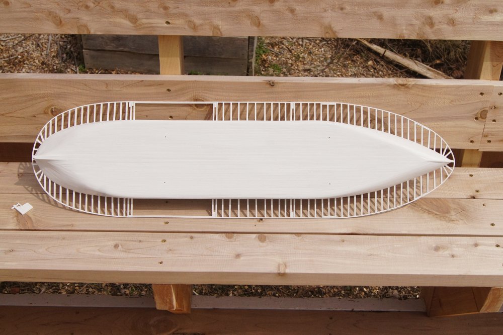
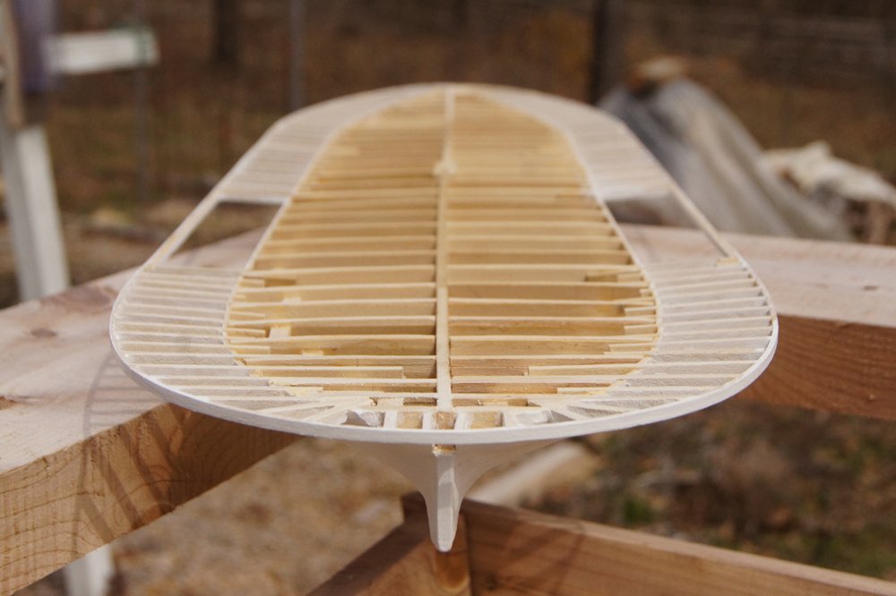
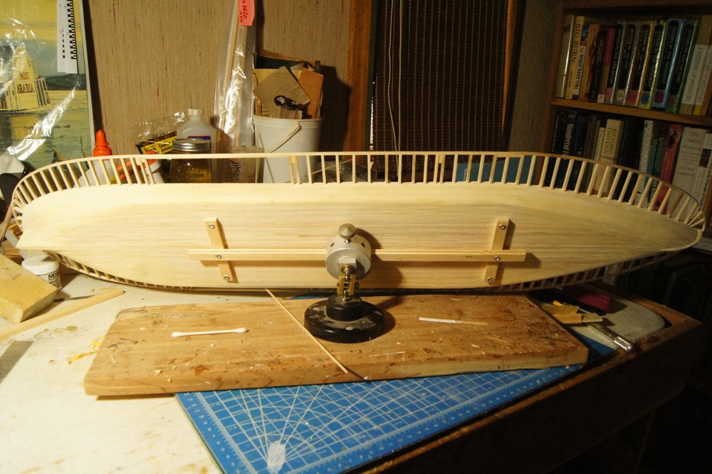
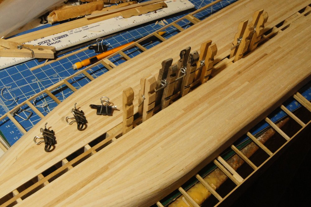
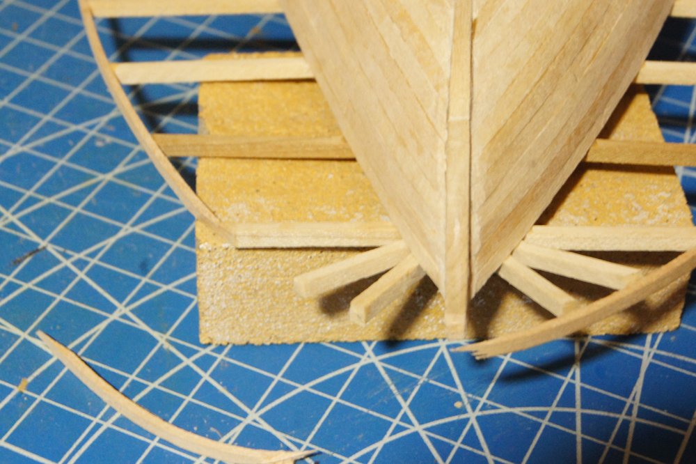
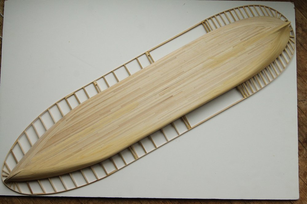
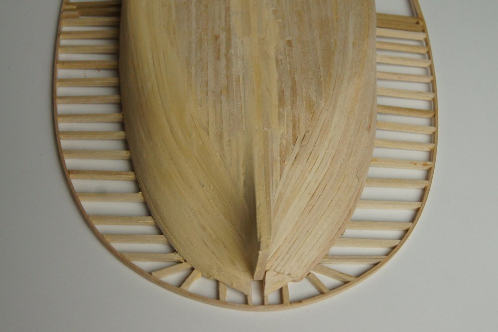
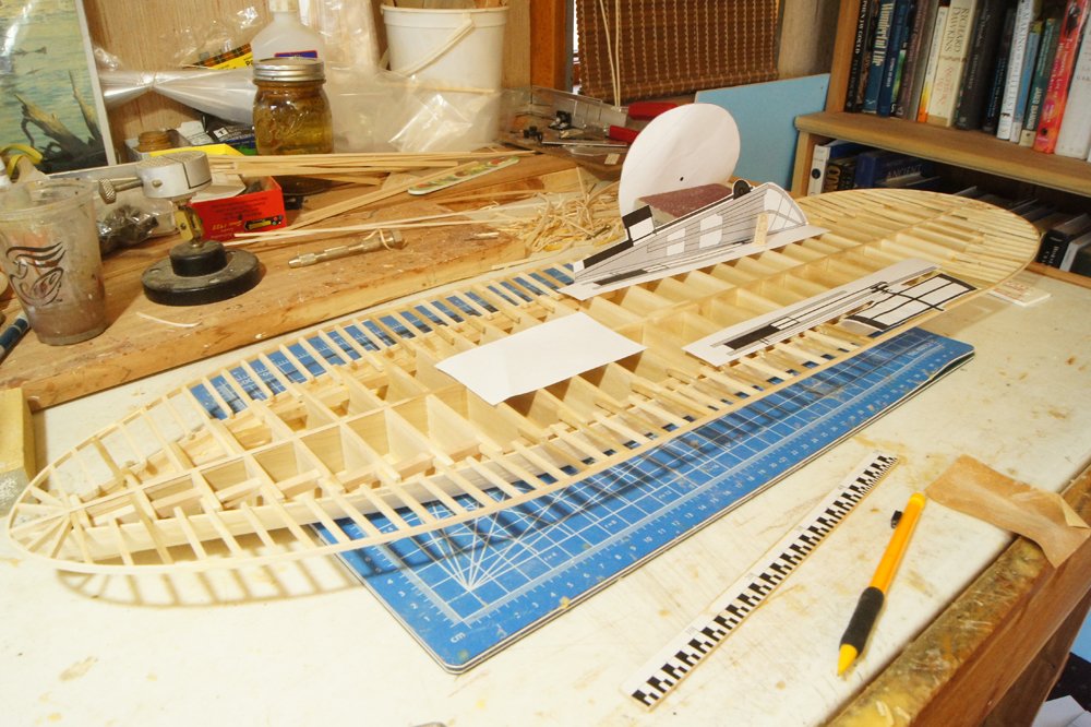
Watching the winter Olympics has both slowed and helped my work. Slowed, because it's been an evening time sink watching so many events I enjoy. Helped, because I moved into the final parts of hull planking that required more careful shaping and manual gluing, so it gave me something to do while messing with individual planks. I've been planking from the outside in, and once I got too near the centerline, my normal binder-clip clamps (black, below) wouldn't fit anymore. So I started using reversed and halved clothespins instead, whose angled shapes work quite well as wedges (also below). Their clamping parts aren't doing anything, but wedging them into the narrow gaps between plank and the center bulkhead worked really well, at least for straight areas. For curved areas, I mostly did this manually and watched Olympics. But I was really pleased with this method. Then I made a frustrating mistake, managing to snap off a big chunk of the curve bow guard extension. It actually wasn't hard to repair, I just cut away most of the bow's curve on both sides, and bend and inserted a new piece that fully swept around that curve. It's not quite as nice as the original because the new joint was harder to hide, but when the model is finished it won't really show. I was still very annoyed with myself because I've been so careful in handling. So here's the planked hull. Note that in this photo I've begun inserting the extra guard timbers at the stern, but not yet at the bow, to bring them up to the right density. If I had decided to plank over the underside of the guards, I wouldn't have needed to do this, so hadn't until the decision was made. But there's abundant evidence that leaving the guards open underneath is the right approach, so in go the rest of the guards. As you may be able to tell above, I also used some wood filler to match a few less-than-ideal gaps in planking, mostly in the complicated stern area. Above, I've applied it to the starboard (lower) side but not yet the port (upper side), and haven't yet sanded it down. Below is a closer look at the stern, with one side filled and one side not. In this photo, it has been sanded. It's definitely smoother now but the planking lines still show through. I'm pleased with how this came out overall, though I did struggles to get the run of planking right and could probably have done it better. Those odd extensions at the very stern are on the real thing, I'll come back to that soon when I show the building of the rudder. And here she is with all the guard timbers installed, right side up with my machinery templates laid out for reference. If you look closely at the starboard wheel area, you'll see a little vertical wooden thing that doesn't resolve well in the photo. That's my rough person for scale, he's about 5'8", shorter than me but about right for the period. The wheel is in about the right vertical place and orientation. The plain white rectangle represents the boilers. So that's where Arabia stands post-Olympics. Next up, I need to cut way too many short strips of hull planking to fill in the last strake between all the guard timbers, then do any final hull finishing necessary. I'll paint the hull next before proceeding to planking the deck, and also will finish the rudder, though I probably won't install it until the very end to keep if from being knocked off. Then, finally, I'll move toward deck planking. Thanks as always for following along. Hopefully this starts to get more interesting soon as we turn her right side up and the machinery and superstructure get underway.
- 599 replies
-
- 16
-
-
- sidewheeler
- arabia
- (and 4 more)
-
If you want to be realistic, I believe that the aftermost part of the cabin was often reserved as the ladies' parlor. The mens' "gambling parlor" would probably have been further forward, to keep their cigar smoke etc. from bothering the ladies. Of course, any given boat could do it however they liked. I see you're watching Olympics too. They're slowing me down by distracting me, but helping by entertaining me while holding down fiddly glued bits. Glad to see you're making progress!
-
Bill, Thanks for checking in. The build log is titled "Ranger" because that's the name of the kit, making it easier for other builders to find it; I know there was no such real vessel. I always intended this to be a fictional "representative" build, and if you look closely you'll see I named her "Ocracoke", on the alternate-timeline assumption that she was stationed near my favorite part of the US coastline. As for the Coast Guard drawing, I had hoped it was accurate coming as it did from a USCG historian, but I knew I wasn't going to get all the details right anyway given how screwy the original kit was and my overall lack of sufficient knowledge. I read a few books on the history of pilot schooners and revenue cutters and did my best to capture the essence of these fascinating craft. Luckily for me, here in the rural Midwest, there are very few people who can or will notice my mistakes!
- 96 replies
-
- 1
-
-
- topsail schooner
- revenue cutter
- (and 3 more)
-
It's amazing how obsessed people get with cheapness at the expense of all rationality. Sorry you have to deal with that crap. Try to keep in mind that you don't hear from all the people who do respect your work and think your prices are fair; it's just not in the human nature to send random emails or phone calls saying "attaboy" even when it's deserved. When's the last time any of us took the time to write/call a restaurant we really enjoyed, even though we'd be far more likely to write/call to complain about a problem?
- 130 replies
-
- 12
-
-
So cool. There's going to be a massive group build on MSW when this sucker hits the market. So...many...build logs!
-
That certainly supports the "no planking under the guards" decision. Wish I could see the true underside of the hull. Thanks, Kurt!
- 599 replies
-
- 4
-
-
- sidewheeler
- arabia
- (and 4 more)