kurtvd19
-
Posts
3,043 -
Joined
-
Last visited
Content Type
Profiles
Forums
Gallery
Events
Everything posted by kurtvd19
-
 Mick: Very nice work and I just love the way it's turning out. Kurt
- 504 replies
-
- 3
-

-
- washington
- galley
- (and 1 more)
-
Airbrush
kurtvd19 replied to Mike Dowling's topic in Painting, finishing and weathering products and techniques
The subject of Chinese – or other – rip off’s of manufactured products is something MSW and the NRG do not condone. There will be a listing posted adding rip off copies of airbrushes to the list of banned items that are not allowed to be shown or discussed. The Chinese are so blatant in their copying of patented products that they have actually solicited Badger by sending samples of their copied Badger products asking for Badger to purchase from them due to price. It does no good to try to take them to court – something that somebody the size of GM can do but not the smaller companies like Badger. The quality of these rip offs is very poor at best. It doesn’t even take a real close examination to spot the differences. I have seen poor fits of soldered pieces that could not possible hold paint as well as regulator pieces without properly drilled vents. Pure garbage. The US courts take this kind of practice seriously. Back in the mid 1990’s Chandler and Thayer Airbrush copied a Badger airbrush patent. They failed to follow a cease and desist order and Badger finally took them to court. Badger won a three or four year court battle in 1999 and the damages against Chandler and Thayer were in excess of the worth of the Chandler and Thayer Company. Badger was given the keys to the business in the settlement. You can still buy a Chandler and Thayer airbrush, but it’s now made by Badger. This is serious stuff. Don’t fall victim to purchasing this garbage – support legitimate companies, workers and jobs. I have worked as a consultant with Badger Airbrush Co. since 1999. I developed their Modelflex Acrylic Marine Paints for them and regularly demonstrate and instruct the use of Badger airbrushes and paints to model clubs and conferences. I have first-hand knowledge of the Badger products and of the rip offs, and am not relying on rumors or a friend of a friend stories. Kurt- 56 replies
-
- 13
-
-
Airbrush
kurtvd19 replied to Mike Dowling's topic in Painting, finishing and weathering products and techniques
Daddyrabbit 1954: The Harbor Freight knock off is an illegal copy of the Iwata. The Chinese companies rip off the legitimate manufacturers here knowing that they can't be sued - due to Chinese government condoning the practice and making it impossible to stop them. They have copied Iwata, Badger, Pasche with impunity. Harbor freight only sells them so they can't be held responsible. I don't know about the other manufacturer's but Badger will fix any of their brushes for the mailing costs back to you (except for bent needles). The Chinese knock off breaks (and they will) - buy another - no service - ever. And if you hold a rip off up next to a legitimate brush you will see that the Chinese quality is pure garbage in comparison. This is the same thing as the Knock off kits that are banned on MSW. Kurt -
Airbrush
kurtvd19 replied to Mike Dowling's topic in Painting, finishing and weathering products and techniques
Roger is right that the air supply is as important as the airbrush. Dry air at a constant pressure is the main thing. An in-line water/moisture trap is needed with all compressors as well as a good pressure regulator. Both are built into the compressors from the home improvement or auto parts stores. For some reason the airbrush people look at these as an add-on. A combo pressure regulator is about $25. Kurt -
Airbrush
kurtvd19 replied to Mike Dowling's topic in Painting, finishing and weathering products and techniques
Mike: One thing I didn't mention was the cleaning of the airbrush. Regardless of brand or type they are not as hard to clean as many think. There are great videos of how to clean them on YouTube. Just don't delay the cleaning and you will not have issues. Kurt -
Airbrush
kurtvd19 replied to Mike Dowling's topic in Painting, finishing and weathering products and techniques
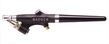
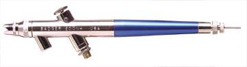
Mike: I use Badger Airbrushes and have quite a collection of them - an even dozen at this point. What I will say about airbrushes is based on my use of Badgers – but will apply to any name brand airbrush. I found early on that the brush must fit the user. I can not use the fat barreled airbrushes, like the Badger 175 (left below) or Pasche VL. They just don’t feel right – but some swear by them – though I use a fat barreled pen for writing. To each his own. The simplest airbrush I would recommend for the beginner who plans to airbrush occasionally would be a Badger 350 (middle below). I learned to airbrush with the original model of this airbrush – the Bink’s Wren – when I got one for Christmas when I was in 8th grade. It’s the only one I had until many years later. I painted cars, planes, sweatshirts, T shirts, and boats with it – winning several gold medals. It can produce very good paint jobs. I was told by the judges at the WI Maritime Museum’s competition (long before I became the contest director there) that one of my tugboat models (it won a gold, modeler’s choice and best Great Lakes awards) missed winning best of show because “No tugboat ever had that good a paint job”. I know that other modelers who have won gold medals at this contest have used this or a very similar airbrush. The 350 is an external mix, single action airbrush. The paint and air mix outside the airbrush on the way to the painted surface (much like an aerosol spray can) and the surface produced while not the absolute smoothest that an airbrush can deliver, I think it is perfectly adequate for wooden models. The 350 will handle all the paints we usually use on models. For the best possible finish then an internal mix airbrush is needed. The paint and air mix inside the airbrush and exit the nozzle very finely atomized. There are single action and double action internal mix airbrushes with the single action being the easiest to use. A good basic internal mix airbrush would be a Badger 200 series (right below) with a medium needle and spray regulator. Medium needles are identified by two fine grooves at the blunt end of the needed and the medium regulators have a stamped IL or are blank (all other sizes have stamped id’s – only the medium would be blank). The medium needle/regulator will handle all of the model stains and paints including acrylics we usually use. There are numerous videos on the net to show how airbrushes are used. Price might be the determining factor for many modelers. The following link shows many brands. Some I am very familiar with some I am not, but this place doesn’t sell junk. I am sure you can find a supplier on your side of the water who handles most of these brands. http://www.chicagoairbrushsupply.com/airbrushes1.html I Hope this helped a bit. Kurt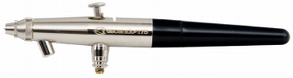
-
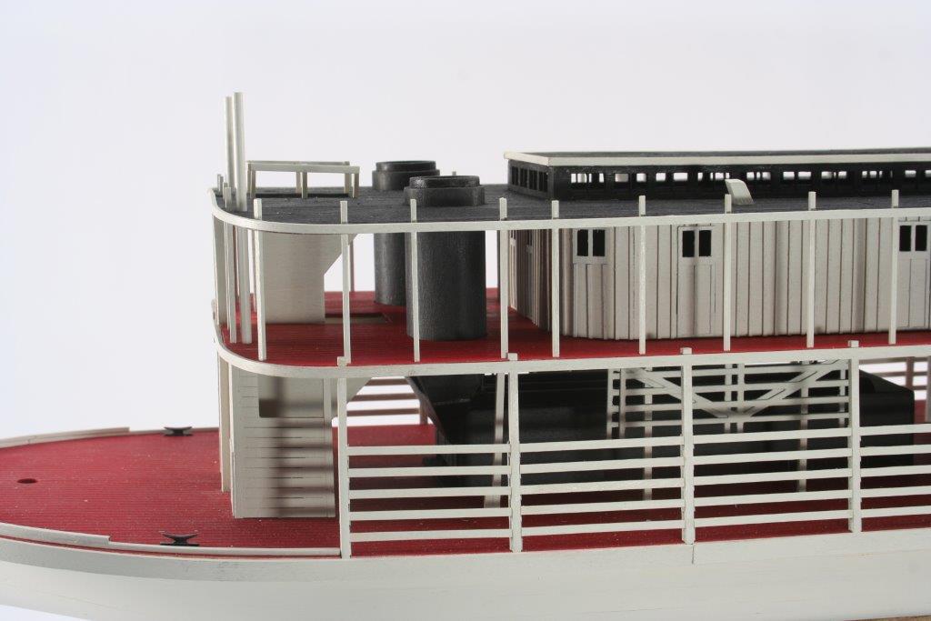
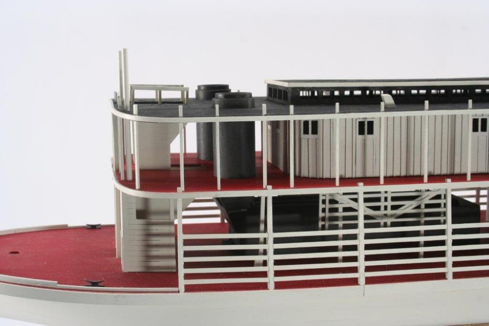
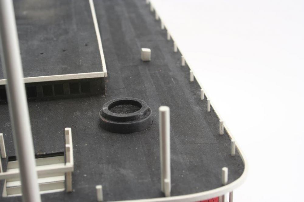
Mike: I was watching - here's what I did with the decks. The main deck and boiler deck are painted with Badger Acrylic Modelflex Marine Paint #16-401 Anti-Fouling Red Oxide (same as Boxcar Red Oxide #16-14 in their Modelflex RR paint colors). I use only Badger Acrylic Modelflex Marine Paints and use Badger airbrushes except for the occasional brush touch up. The finger joints on the boiler deck and the upper decks went together seamlessly with just some filling of the butt joints. The "tarpaper" on the upper decks/roofs is Silkspan meant for aircraft models. I think rice paper would work as a substitute as I think it was mentioned somewhere on MSW that Silkspan isn't being made for the aircraft modelers now. The tarpaper is glued down to the deck using Artists Matt Medium. The brand I used is Winsor & Newton Galeria Acrylic Medium. It is a think, white liquid that dries completely clear. I used a scalpel to cut the silkspan into scale 3 ft wide strips. I kept the scale length to 20 ft or so. The silkspan was laid onto a sheet of glass and the matt medium was brushed onto the silkspan getting a good coat onto it. The strip was laid down onto the deck/rook and smoothed into place. The next strip was laid end to end with the first with a slight overlap - you want the overlap to show. About a scale 3-4 inches. The strips were laid down the full length of the exposed deck. The next strips were overlapped along the length of the strips about the same as the end to end joints on the first strips. The end to end seams were also overlapped. Don't worry if a bit of the matt medium oozes out of the seams as it will have a slightly darker appearance that will look just like tar had oozed out of the joint. The lower photo shows the tarpaper seams - sorry about the construction dust in the photo. The surface was brush painted after the strips were all in place using Badger Acrylic Modelflex Marine Paint #16-413 Wrought Iron Black (Same as Weathered Engine Black [#16-05] in Badgers RR line of Modelflex Paints. Looking at many riverboat photos show that with very few exceptions tarpaper covered the upper decks that also served as roofs. There were sometimes planks laid out to make walk ways to prevent foot traffic from opening up leaks. These decks were for crew use only. Any area of these upper decks intended for passenger use had planks provided as a walking surface. The planks in passenger areas were held together with cross wise battens on the underside - this also elevated the planks a bit off the surface to keep things dry under the planks. I hope this helped. Kurt
- 225 replies
-
- 12
-
-
- chaperon
- model shipways
- (and 1 more)
-
Mike: Like Carl said, you can't let us down. You learn from a mistake, do the best you can do and try to do better next time. This is what it is all about. I think the deck looks pretty good now. Kurt
- 225 replies
-
- 3
-
-
- chaperon
- model shipways
- (and 1 more)
-
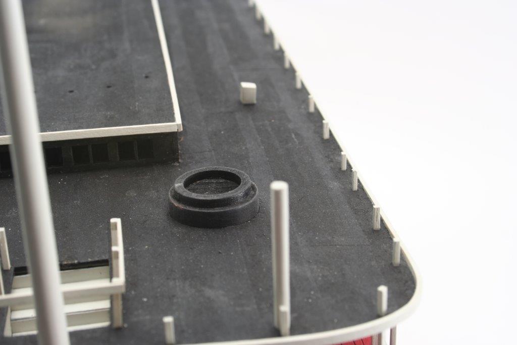
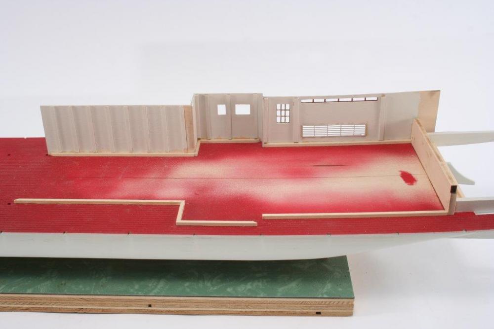
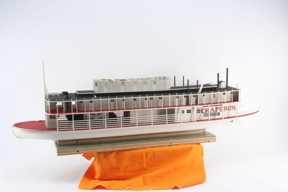
Mike: I have attached 2 photos of my Chaperon when it was under construction. Sorry but these are the best photos I have of the area in question but they might help. If you are able to very lightly sand the paint to knock off a bit of the shine I think that you will have a pretty nice deck. The areas of the notched plank joints are pretty well hidden once the model is finished and as suggested some bit of cargo can hide most of it, but I just went into my loft to examine the model and with the location of the joints between the back of the boilers and just ahead of the cabin I just can't see the joint at all. The first photo shows the deck with the starboard cabin walls in place and the port side ready for the walls to be put in place. The seams are directly forward of the end of the forward end (left in photo) of the cabin walls. In the lower photo this area is shown with the main deck completely finished. With the railings at the deck edge there just isn't much visibility of the planking seams. As to the lack of plank butt joints the only areas this will be visible is the fore deck area and the aft decking by the Chaperon name. It's your decision regarding planking over the deck. As to the holes for the various posts and locating the structures I would handle these as you do the planking by notching the planks for each square hole as you fit the planks that will cover them. I found that I had to fit each post to it's hole by either enlarging the hole with a square file or sanding the bottom end of the post. Mark the planks as you cover any of the laser scribed locating lines. Doing it this way would eliminate the need for a pattern. Using think planking the trim board at the perimeter of the deck might need to be a bit wider or you might be able to use the kit provided pieces - I just don't remember how much they extended below the kit's deck. I hope this helps. Kurt
- 225 replies
-
- 9
-
-
- chaperon
- model shipways
- (and 1 more)
-
Foredom rotary tools.....how good are they?
kurtvd19 replied to mrjimmy's topic in Modeling tools and Workshop Equipment
Jim: I have had one for 15 years or so. Very smooth. 10X better than anything Dremel makes. Not noisy. Occasional lubricating of the flex shaft drive is needed but it's real easy - lube is in a tube - disconnect from the tool, drop some lube into the flex shaft housing reattach. I have the cc model with the std hand piece. Very happy with it. I don't use it for carving any more as I now have a dental machine for carving but the Foredom is a fine tool. It will go very slow and I have done a lot of trimming with sanding drums of fiberglass and styrene w/o melting the styrene. It can also spin like crazy to hog out wood. Kurt -
Mike: Sounds like you have the problem solved. Roger: That's interesting - but we would probably need a scale cow! I have to sit down and do a page by page read of both of Bates' books. Have used them for reference many times reading the relevant parts but you have convinced me that a thorough read is due. Thanks, Kurt
- 225 replies
-
- 2
-
-
- chaperon
- model shipways
- (and 1 more)
-
Mike: Test on scrap basswood. The frets that the parts came out of works well - same exact wood so results will be same. Kurt
- 225 replies
-
- 5
-
-
- chaperon
- model shipways
- (and 1 more)
-
Mike: Looking good. The deck is glued down tight so there is no worry about warping at this point. I airbrush, but this works with brush too. Wet the wood - dampen the wood is more accurate - let it dry and you will see that it has fuzzed up. Sand lightly to knock off the fuzz and dampen it again. Re-sand and then paint. There might still be a bit of fuzz, but much less. A very light final sanding will give a smooth surface. I use a very worn sponge sanding pad (by 3M) for this. Another way to avoid the soaking in of the paint and fuzzing of the basswood is to apply Shellac to the wood - the Shellac seals the wood. A very light sanding and then paint. Kurt
- 225 replies
-
- 6
-
-
- chaperon
- model shipways
- (and 1 more)
-
Mike: I would go with the oxide red for the decks and the wheel. Anything red would be the same red. Kurt
- 225 replies
-
- 3
-
-
- chaperon
- model shipways
- (and 1 more)
-
Mike: Put it in a case!! I used to make a lot of $$ cleaning models that were not in cases - gave it up as it was sad to see the same models a few years later that had deteriorated more by the constant exposure. Kurt
- 225 replies
-
- 5
-
-
- chaperon
- model shipways
- (and 1 more)
-
Mick: Outstanding work. Thanks for sharing this with us. Every time somebody asks us about the plans I tell them to check out your build. Thanks, Kurt
- 504 replies
-
- 6
-
-
- washington
- galley
- (and 1 more)
-
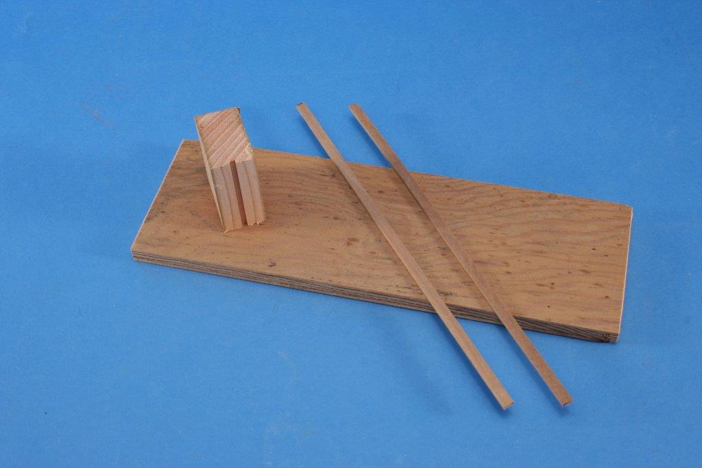
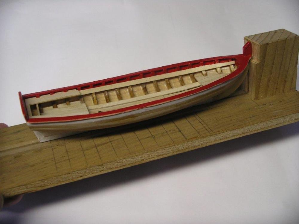
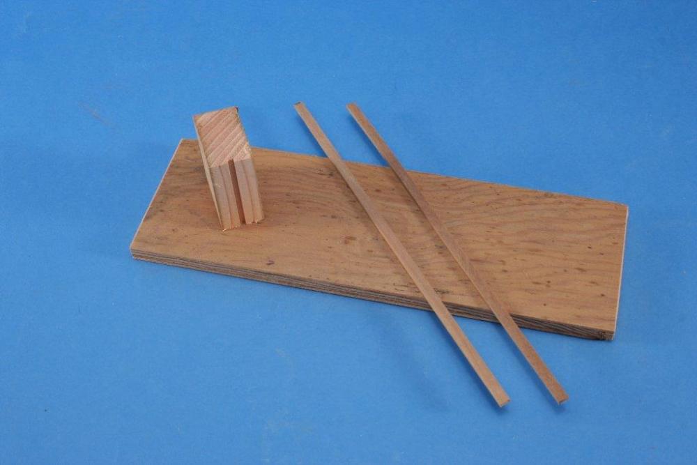
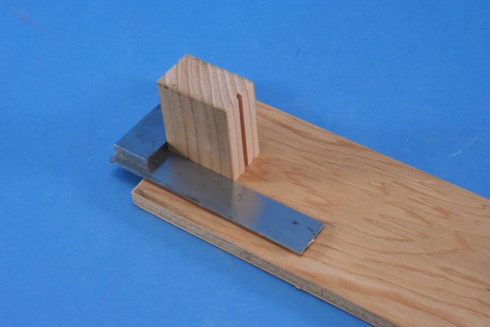
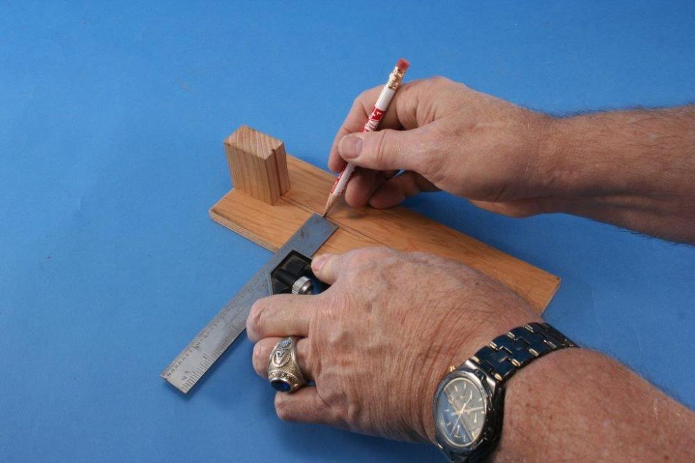
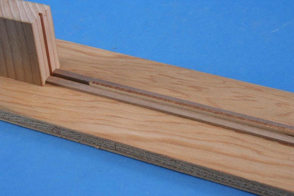
Will: Here are some photos of the jig used by several modelers who built the longboat for the Tri-Club build. It should be self evident how the jig is made and used, but if you have a question just ask. Kurt
-
Mike: No, I didn't forget, just very busy. Will get them to you this coming week for sure. I agree that Oxide Red is a good color for decks and the wheel. It was commonly used and cheap. The Ronnberg colors are not on the NRG website. However, they are in the Shop Notes 2 book we sell from the web site. The printing of the colors was expensive to assure they were accurately duplicated in the SN2 and for the accuracy of the colors to be true showing them on the website is not possible due to many variables in monitors. Kurt
- 225 replies
-
- 4
-
-
- chaperon
- model shipways
- (and 1 more)
-
Mike: I told you not to dread the hull planking. It looks good. Kurt
- 225 replies
-
- 3
-
-
- chaperon
- model shipways
- (and 1 more)
-
Steamboats and other rivercraft - general discussion
kurtvd19 replied to Cathead's topic in Nautical/Naval History
Sal: The article Roger mentioned is not yet available in the store but I am checking to see if it has been converted to go up onto the site or not. If it has been converted I can arrange to get it o you for the same fee as listed on the web site store. we have a lot more articles than are listed ready to go but we are contemplating a site revision and don't want to make double work for the web masters. Those additional articles will be available once we sort out if we are going to change. Otherwise I can print the pages in question off the CD's we sell, with all of the Journals archived, and can arrange to mail it to you. I will post here when I find out one way or the other about the availability / method. Kurt- 281 replies
-
- 6
-
-
- Steamboats
- riverboats
- (and 3 more)
-
Elijah: We missed you at the meeting last night - have fun in camp. Kurt
- 701 replies
-
- 3
-
-
- phantom
- model shipways
- (and 1 more)
-
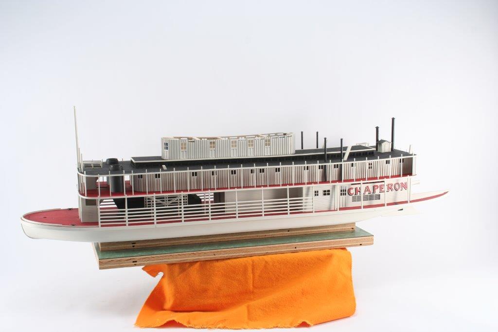
I agree 100% with Cathead on the colors. Red was by far the most common deck color though brown was also used. Most hulls were white but black was also used. Check the photos I had posted of the Chaperon to see the white hull, but the photo I posted of the model made by Sam Parent had a black hull and made a very attractive boat. If you are going to model the Chaperon as the Chaperon then I would definitely go with the white hull but if you change the name use black or white. Kurt
- 225 replies
-
- 5
-
-
- chaperon
- model shipways
- (and 1 more)
-
Steamboats and other rivercraft - general discussion
kurtvd19 replied to Cathead's topic in Nautical/Naval History
Yeah, Cathead, I agree - very interesting and I am going to do some checking on the sources Roger has cited. I figured a boat was a boat - but being wider than average sure makes sense for the use. The Chapelle book though is the one I do not have! Kurt- 281 replies
-
- 3
-
-
- Steamboats
- riverboats
- (and 3 more)