dafi
-
Posts
2,430 -
Joined
-
Last visited
Content Type
Profiles
Forums
Gallery
Events
Everything posted by dafi
-
 All the ready made ones have far too big nails - some could be called rivets or even bolts ;-) - - and most of them are to thick too. The best in my opinion so far is the self adhesive copper foil combined with some imprinted nails. I used a small tool based on my wife´s derma roller - please do not tell her, she still is looking for it :-) A german friend used the foil for a larger scale with a self made stamp, the kind o that is often described in the literature. XXXDAn #1099 #1114
 -
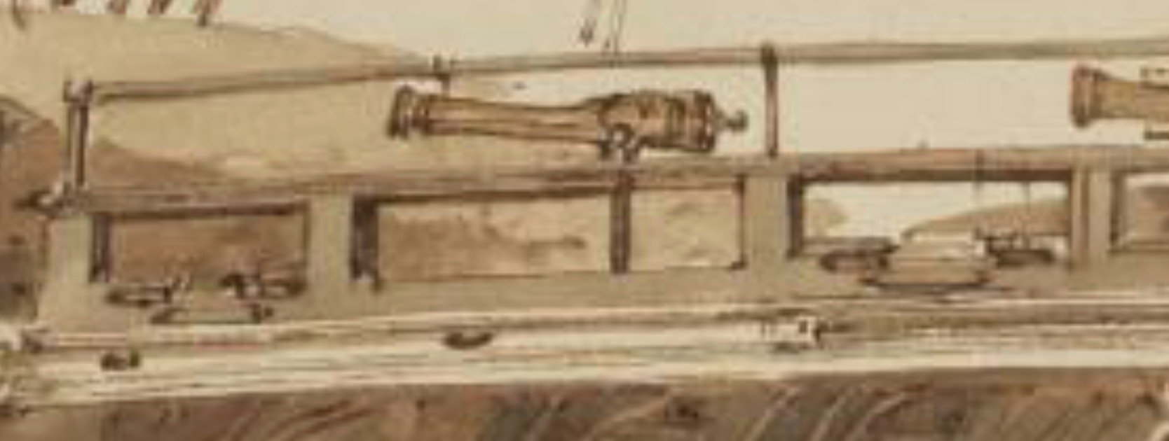
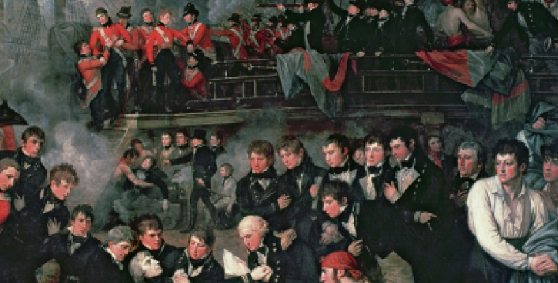
So coming back to the mysterious topic of the Turner drawing. Plenty to be found in there, what a joy. We also had a longer fruitful discussion on our german forum, let me resume the findings. First of all we found some better resolutions for the Turner drawing and painting. The same kind of rail can be seen on the painting from Benjamin West from 1806, also showing the swifels and I also believe the fairlead rollers. If he copied from Turner I do not know, but he is reported to have seen 50 survivers of the battle portraying them. https://en.wikipedia.org/wiki/The_Death_of_Nelson_(West_painting) These are some hints, but still there is a conclusion to be made, here is my personal one. There are some remarkable details on the Turner drawing. But we have to remember one big thing: This is a ship after some emergency repairs after the battle, that could explain some of the "strange" details. First of all the woolings on the mizzen mast, where one could expect iron loops. Her again it could be a jury mast or - as to be seen on other of Turner´s drawings - some fishing to help the injured masts. The binnacle could be either an after battle replacement - as the wheel got shot away, the binnacle could have been too - or an "in ordinairy version" - as the ship is already largely stripped of equipment. The helm indicator shown can also be found on the model from 1765. The last opening underneath the poop is a gunport where there should be a door. But again, the ship clashed against her opponent´s sides and some parts of the galleries were damaged. This too could be a simple emergency fix for security reasons. The hammock cranes of the poop are nicely visible and seem to protrude further forward than today. Some structure appears underneath the ripped (?) canvas on starboard. I do not yet figure out, how solid the bulk-ward in this area was constructed, here it looks like the hammocks are hanging outwards, other drawings do look like a flush outside. But my guess is to see a wooden railing underneath. Can the two bars on the side be part of the sauve tete netting? Also the small gangways are leveled with the quarter deck, and not 2 steps underneath, thus giving more headroom for the guncrews and also being a reason for the hammocks to protrude further forward. And finally the rail. Again, we have a repaired version shown. The upper part was reportedly shot away, also to be seen on the Turner´s painting "as seen from the mizzen mast". The 4 fair-lead rollers could have been used to handle the ropes from the mizzen mast, as the place there was restricted, the access difficult and also the structure reportedly quite weak. So the ropes could be passed onto the quarter deck where they could be handled from more men with more ease. This is also supported by the pair of eyebolts beside each fairlead roller as those could be used to attach some block and tackle to ease the job. Also it includes ropes coming from the center/mast but also from the shrouds area, hence the rollers on both sides. The upper part of the railing is a reconstruction after the battle, but fits other versions of this timeframe. Now come the interesting bit - the swifels. My personal opinion is, that those were just added mere for signaling purposes as all the other guns were already taken out. Essential for those days signaling and no other use to be seen so far. The upper part of the Rail are for stanchions with a wooden bar crossing. Here it could be a replica of the prior battle state (even I would have expected more stanchions for normal use) or it could be a jury fix, replacing the shoot off hammock cranes. I took the artistic license and opted for the hammock cranes, even though not as high as seen today on the Viv in P. :-) This led me to my interpretation of the turner drawing: Still have not decided upon the fire buckets. It is mentioned in the contemporary sources (Steel?) but with the fairleads and the indicator appears to be too much. Anyway I have prepared the holes for the hangers, but those could be closed easily with bit of paint. Other interpretations always welcome! XXXDAn

-
Just a small feedback from the tinkering corner. Opted for a light colored indicator as a black one like on Royal George was difficult to spot. XXXDan
-
Thank you Mark, Frank, Jan, Wacko, druxey and Pop, very appreciated! and miracles do happen: Univers gave me a nice X-Mess-presi - some tinkering time :-) A short look back: Some time I discovered on the William Turner drawings from late 1805 some details on the poop deck rails. After some fruitful discussions it proved to be most likely some fair lead rollers that were used for hauling some rope from the poop deck rigging, due to the limited space there and the restricted access. So plenty of men could pull the strings from the quarter deck, with more ease. More here: http://modelshipworld.com/index.php/topic/13182-thinking-things-through-detail-in-turners-work-on-the-poop-deck-railing/ Also the helm indicator was rediscovered on the drawing and also to be seen on the contemporary model from 1765. Reason enough not to omit this one any longer ;-) http://modelshipworld.com/index.php/topic/13202-thinking-things-through-axiometer-or-helm-indicator/ So then off it went :-) First the still missing most upfront deck beam still had to be placed. The white sheet served for positioning. Then some trials to get the proportions of the clamps and rollers correct.. Here in comparison to the Heller Part, that is based upon todays state of the Vic in P. Then slowly getting in touch with the base part of the rail. Clamp and rollers are composed out of several small parts to give a defined form. And then on location. The gaps on the sides will disappear on the final fixing, as the material easily bends in the shape of the curve of the deck. Splashed some paint ... ... and placed in place. XXXDAn
-
You are right Frank, closer one can´t get! I do believe, that this collection is not the first one being issued, there are other books with a different choice of letters too. So it can easily be that your feeling does not betray you and you read something alike :-) XXXDAn
-
Oups, sorry I thought it to be a contemporary book of the 18-hundrets ... Thank you for clarifying! XXXDAn
-
As it is old enough to be public domain, is there a online version of this book available? XXXDAn
-
Microwaving the wood?
dafi replied to a topic in Building, Framing, Planking and plating a ships hull and deck
Careful with the microwave!!! I once tried it out and after some few seconds the wood was charcoal, the alarm ringing, the house smelly, the wave had to be replaced as no way of getting rid of the smell inside and the worst: the piece of wood was lost ... XXXDAn Epilogue: Still today the Admiralty looks cautious if I enter the kitchen ...- 12 replies
-
- 11
-

-
That is not the recoil :-) 24 feet is the length of the pure rope. Divided by the middle for left and right minus the "knot" around the eyebolt on the ships side. This makes 24 feet divided by 2 = 12 feet 12 feet minus bores length of 8 feet makes 4 feet left These 4 feet minus 1 or 2 feet for the knot as the rope is quite stiff makes not too much distance towards the hulls side. Fits more or less the model shown in my last post :-) XXXDAn
-
Before the iron guns were painted black (in the 1850ies?) there were a lot of recipes for a "paint" that the guns were painted with. Never tried it out but apparently this coating gave a brownish color. (not like the one that Bluenoses´s guns came like) XXXDAn
-
I love the small film of the Constitution, gives a rough idea, but the details - all participants should be keel hauled :-) First, no breech line installed, then too, the gun could be retracted 2 more feet, thous giving a inside clearance for the muzzle. So those two acrobats would not have to sit outside the gun port. Also handling the heavy shot hanging out - possibly dropping it in rougher seas - if one would have the possibility to do this in a safer (for the shot) and faster to handle environment on the inside. Also the working attitude looks very relaxed ;-) And nice of them turning away from the firing gun - and basically looking at the gun beside that is fired possibly the same moment, jumping exactly onto them. Better move behind the gun, stay clear and a bit more safe. Best to be seen on Master and Commander the bonus disc, were the gun drill for the actors is shown. XXXDAn #1154
- 40 replies
-
- 11
-
-
Not quite right yet, my dear Jan, not quite right. Too two-dimensional. Much more ups and downs, much more like this :-) XXXDAn
-
And then still, the kit was bought on 02 November 2001 and started not too long after, but had a 6 year hiatus due to missing working space. XXXDAn
-
A tad longer my dear Jan, a tad longer :-) That is how the gun deck looked in 2010! As my dear wife says: Did not change too much, did it?!? XXXDAn
-
There are plenty of these systems for fresh water shown in modern compilations and contemporary sources as seen in #40 and in NMM. Some come through the bottom, some come through the sides, some straight into the pump, some filling up a cistern and being pumped from there. And if one looks at all the links here in NMM about the heads and other fecal facilities, one understands, that the fresh water is taken from some way underneath the surface ... In my understanding, the chain pumps were only to evacuate the bilge from normal drainage, condensation and normal leaks and of course emergencies. But back to my mystery of the middle deck chain pumps: The "normal" chain pump for two deckers and lesser ships is quite well documented, as there were hundreds of them being in use. First and second rates were only about 30 in the whole time from 1760 to the end of the era. So that could explain the lack of hints about these "phenomena".
-
Thank you Druxey, but this is what I still doubt. The chain pumps are for the bilge water, and this - in my humble opinion - is not really suitable for cleaning. On top the chain pumps do not give water with pressure, essential for fire fighting with a hose. Both Fresh water and water with pressure can be given by the elm tree pumps, getting their Water from the outside of the hull. So still it remains a mystery to me, why the Princess Royal and many later drawings show cisterns in the middle deck, while early plans show just a part that could be interpreted as a cogwheel with handle. XXXDAn
-
Thank you Walter for your input. If the handles of the crank shaft in the lower gun deck have to be given up, I do strongly believe, that the ship is really lost beyond hope :-) As you state the strongest guess for the upper handle is to have more men handling it. Other reasons are still not yet to be seen, as there seems to be enough fresh water pumps for washing and fire fighting. Just rediscovered this topic as in another place there was another discussion about it and this seemed a good idea to check if any new resources popped up to this topic :-) Cheers, Daniel
-
Thank you Sirs for comments and likes! After the model makers meeting in march I originally wanted to tidy up the anchor handling presentation, in the meantime stumbled over the top-tackle scutles, so it is time to link the both. For this I need the pendants from the tops, so time to look for that ... So first step to worm, smart and serve the rope ... ... bound the loop, threw it over the mast top ... ... and let ot a big scream as the binding was on the half round chock and not underneath ... ...AAAAARRRRGGGGHHHHH... So a longer loop was done and a picture taken for that nobody can say they did not see it properly. And really this time it fits underneath the chock :-). Making the cringles is a mostely easy task and already documented some time ago ... ... oup there the 1 mm tube from the old tests, now the slight thicker one of 1,3 mm :-) But then turning the cringles in, thaaaaat is something different ... Left the first trial, right the newer one, I think some more 2716 pieces and the result will be fine And the pendants in place :-) :-) XXXDAn
-
And following the disaster end of August I proudly declare that Captn Hardy ... ... has the ceiling of his cabin finally repainted :-) And the forecastle is done too :-) :-) ... and some more beauty shots from the kitchen :-) :-) :-) The pikes are only on one side of the mast as the main stay is passing on starboard. XXXDAn
-
Thank you Sirs! As a small sign of life, I did some parts that look easier than the way I wanted them to do :-) The gunwale from fo´castle to waist, the on-molded partners needed to be replaced. In P. they have to rolls for some running rigging incorporated, so that was a "wannahavethat2" ... ...ok, once in the mind, never to leave again. Made a green master, that far that good, but ... ... to get 2 fitting holes into that thin structure proved quite a task. Some pre drilling in 0,25 mm and finalizing with 0,3 mm and the holes were through ... ... and still fitting a base underneath the circular section that houses the spare spars ... ... and then the exciting moment ... ... of the mock rigging, and it worked, the rope went through. XXXDAn
-
For me the best is "The voices of the battle of Trafalgar", a collection of plenty of letters written in the days or hours before an after the battle. https://www.amazon.com/Voices-Battle-Trafalgar-Peter-Warwick/dp/0715325566/ref=sr_1_1?ie=UTF8&qid=1478626444&sr=8-1&keywords=voices+of+trafalgar XXXDan
-
Wood masts for a plastic model... Tips?
dafi replied to SomethingIsFishy's topic in Plastic model kits
Here is a test I did a while ago with Heller Victory´s plastic jib and a replacement wooden one of the same dimensions. Both having the same weight hanging on, does one have to say more? Cheers, Daniel -
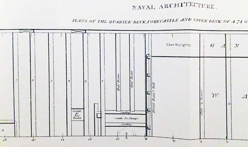
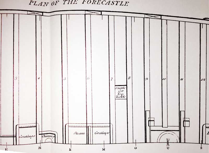
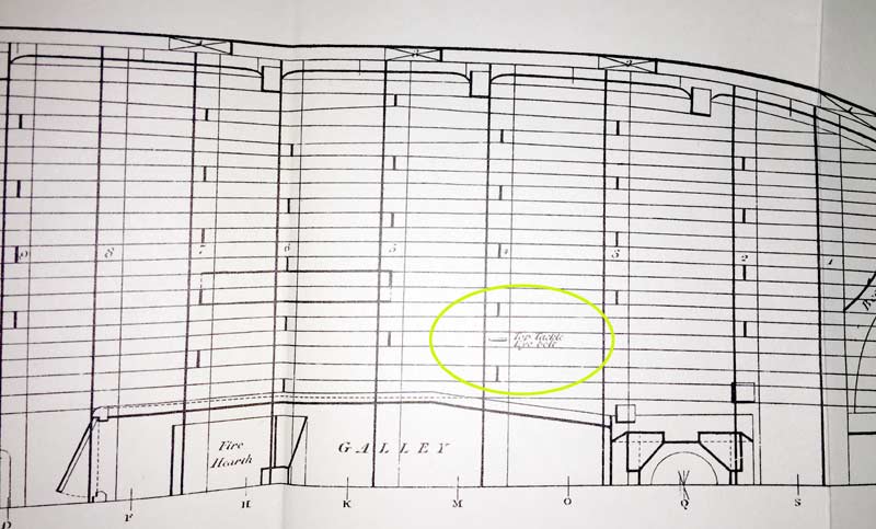
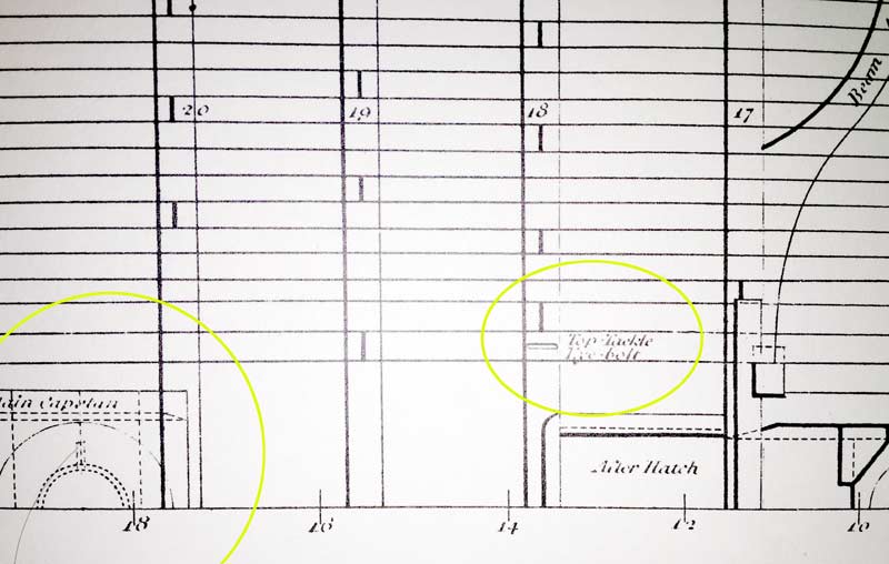
Lost in time ... and found :-) In ... Exactely on the same spot as seen on the model of the Vic, this time on a british 74, signed as "Scuttle to Top Tackle" And even better, the expected "Top Tackle Eye Bolt" is also shown, at the right distance to the capstan :-) Both finds are 50 years apart, does this mean, that this feature was common for quite a while? XXXDAn
-
Actually ... ... some parts out of this box already ended up on other builders Vics :-) XXXDAn
-
US Brig Syren by Gahm - Model Shipways
dafi replied to Gahm's topic in - Kit build logs for subjects built from 1801 - 1850
Simply love what I see :-) XXXDAn