


SteveLarsen
-
Posts
45 -
Joined
-
Last visited
Content Type
Profiles
Forums
Gallery
Events
Posts posted by SteveLarsen
-
-
-
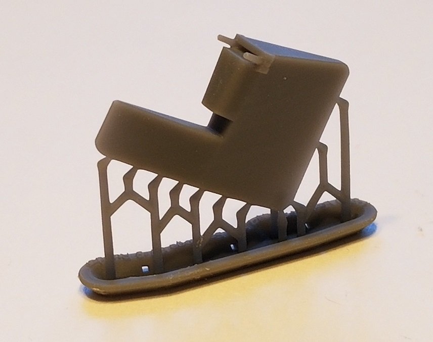
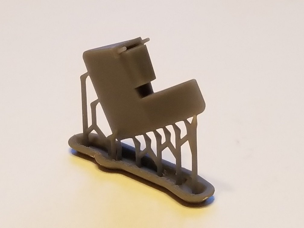
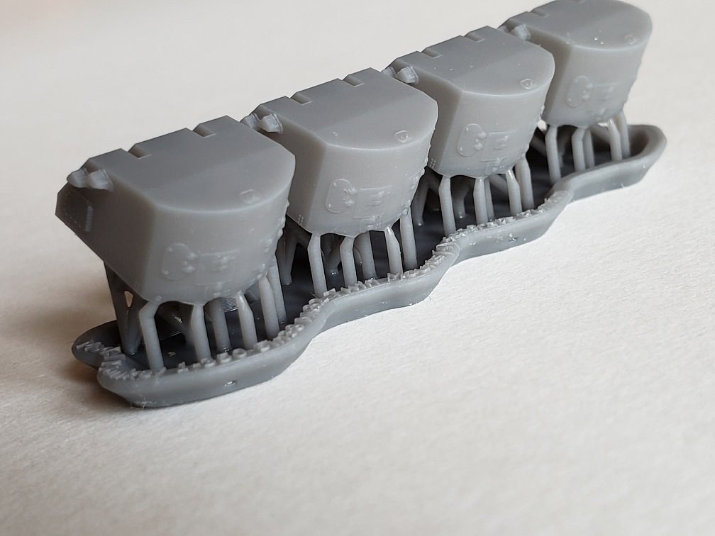
The tubs we offer have an internal working diameter of 15.46 mm, accounting for interior ribs. If the diameter of your mounts is less than 15.46 mm, your mounts should fit our tubs nicely.
The tubs are designed for printing in groups of 3. I can make available a set of 3 and you can order as many sets as you need.
Cheers!
- Canute, mtaylor, Spaceman Spiff and 1 other
-
 4
4
-
Thank you everyone, for the kind comments and patronage!
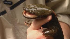
Funny story about our business name. We knew from marketing principles to keep the name simple, choose one that directly relates to what we were selling, and be memorable. An animal helps make the name memorable. And we're located near the Cape Fear River, home to a very large, aquatic salamander with skin covered in a protective mucus from which the salamander gets its very memorable name (photo below). So, after much consideration, our business name came down to two choices: Model Monkey or Snot Otter Hobbies.We settled on Model Monkey®.
Thanks again!
Steve Larsen
Owner, designer, printer, and chief bottle washer at Model Monkey LLC.
- GrandpaPhil, Canute, Ryland Craze and 4 others
-
7
-
Superb. Really enjoying your posts and model.
-
-
-
-
-
-
-
Great subject and nice work. Have popcorn in hand.
- Old Collingwood, mtaylor and lmagna
-
3
-
Enjoying the build! The model is huge!
- Old Collingwood, Dave_E, mtaylor and 1 other
-
4
-
-
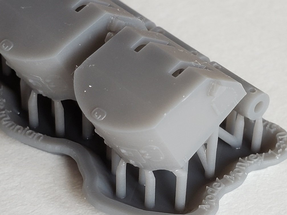
Here are the 3D-printed rudder and 3D-printed 5"/38 Mk.32 mounts. These are Model Monkey products which I designed, print and sell.


- CDW, KurtH, GrandpaPhil and 4 others
-
7
-
Thanks so much!
Very sorry to hear of the loss of your brother on board Sara, Ralph. My family and I appreciate and honor his and your family's sacrifice.
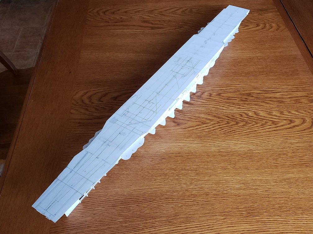
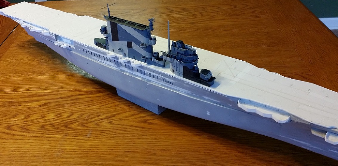
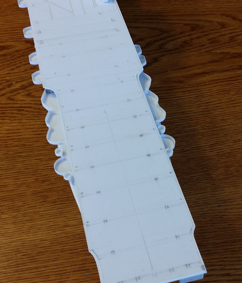
I regret to report the model's hull was badly damaged beyond repair in an accident. But it offered a new opportunity to do better. Hull 2.0 is under construction. Here it is with the framing complete and some planking roughed in. What appears to be the flight deck actually isn't. This is a supporting deck, like the sub-floor of your house, that the flight deck planking will be laid on. Locations of flight deck features have been drawn in. V-groove styrene was used as an aid to align the planking and other features.
The island and funnel were not damaged, thankfully. They will go on the new hull.
3D-printing technology will be used to add additional detail and create very accurate features that were not part of the the original model hull. A new 3D-printed rudder will be attached, too.
Much work to do but having fun.

- GrandpaPhil, oneslim, Rik Thistle and 6 others
-
9
-
Again, we see world class workmanship and rare skills. Truly magnificent.
-
-
-
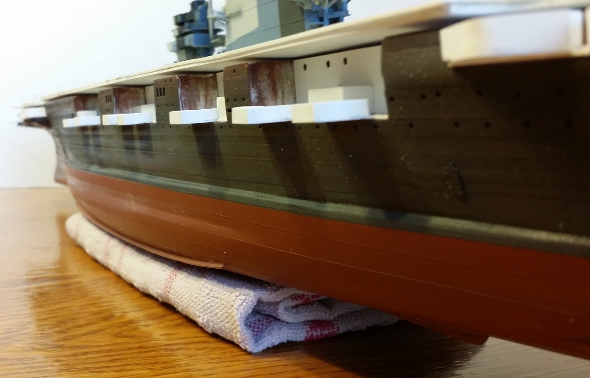
Thank you all so very much for the compliments and encouragement!
The hull has been primed and is nearly ready for paint and further detailing. The red has been smoothed and the black will be shortly. The red is Krylon brand rattle-can "Red Oxide", a dead ringer for US Navy 121 red oxide, and will not be painted further, just mildly weathered. The portholes on the hull will be re-drilled using a pin vise since the primer has partially filled them.Straking detail is visible in the photos.The flight deck (and funnel and conning tower) has merely been placed onto the hull for photo purposes. When the boat bays and AA sponsons are complete, the flight deck will be cemented to the hull. To ensure that the surface of the flight deck is perfectly flat, it will be fixed inverted to a flat surface then the inverted hull will be placed down onto it and shimmed where necessary. Perhaps it is more accurate to say that the hull will be fixed to the flight deck.------------Starboard side. The bottom edge of the black primer will form the boot topping. Late in life, the starboard side of the ship received a large stability blister, visible here on the model. Photos of the ship indicate that the plating of the starboard stability blister was all butt-welded, unlike the rest of the ship, which was riveted when built. Therefore, the blister is very smooth compared with the rest of the hull, which is straked. The starboard side of the ship lost its original bilge keel when the stability blister was added.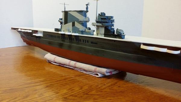 Port side. Bilge keel is visible. Plating pattern around the bilge keel is consistent with photos as is the slight variation in porthole height just aft of the nearest boat bay. The watertight hatch visible in the side of the hull was common to both Saratoga and Lexington. Through this hatch on Lexington, electrical cabling was passed supplying electricity to the city of Tacoma, WA for a month beginning in December, 1929. Notice also that the portholes inside the boat bay are much larger than those on the hull's shell plating. This is consistent with plans and photos.
 The model's engineering vents are all open. They need some minor cleanup but otherwise are done.
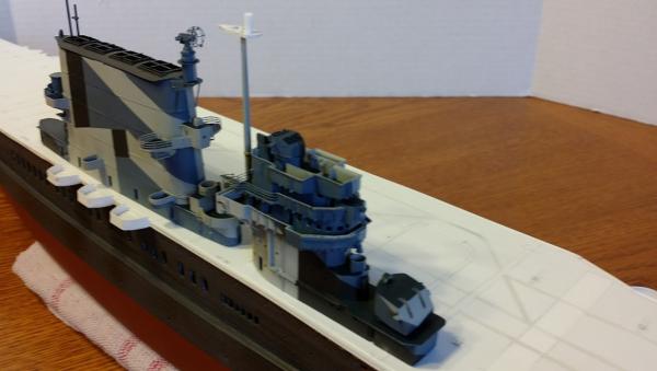 The real ship was built with tracks to move floatplanes on carriages around the flight deck. The floatplane tracks are visible on the model's flight deck. Photos of the real ship indicate that the tracks originally featured a centerline slot but by 1944 the ship no longer carried floatplanes so the tracks were no longer necessary and the slot was eliminated. Thus, the model's tracks are solid.
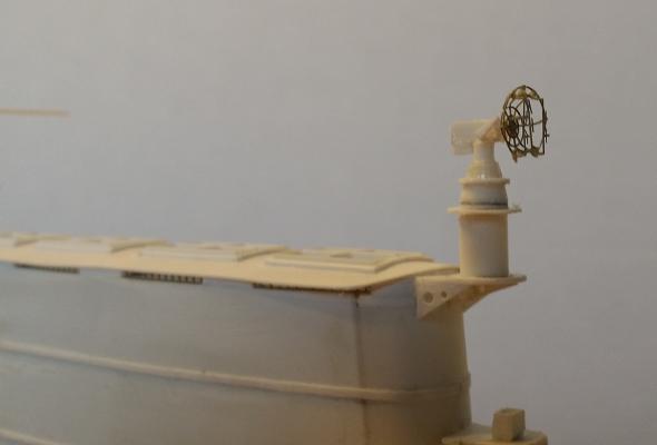
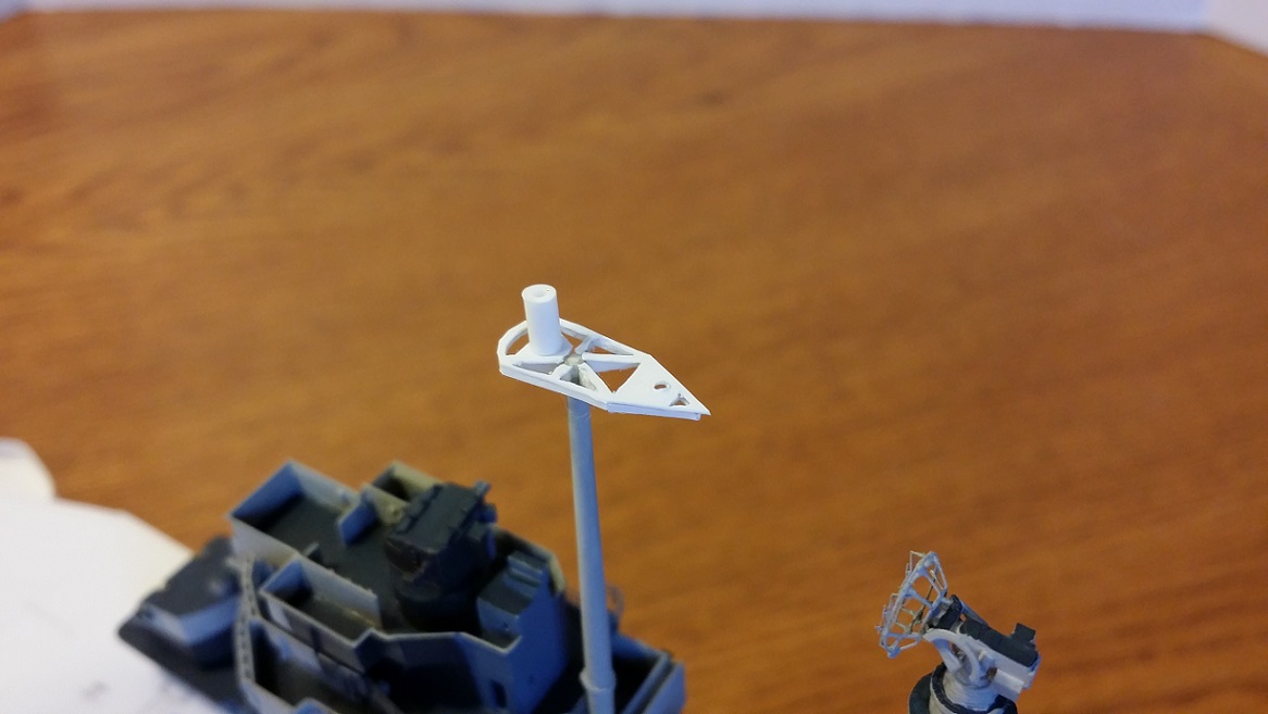
 This is the radar platform on the foremast.
 Best wishes!Steve
 -
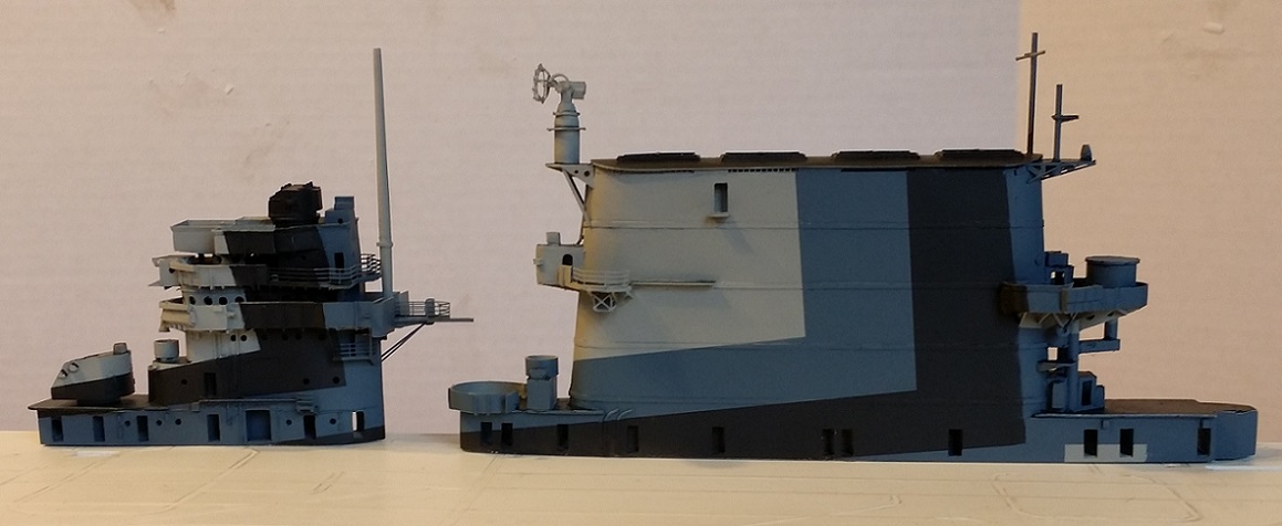
Here are some photos of the conning tower and funnel painted in Measure 32 11a consistent with photos of the ship taken in September, 1944 appearing in USS Saratoga Squadron at Sea by David Doyle. There is still some adjusting and tweaking of the pattern to be done but generally it is ready for additional detailing.
The colors are acrylic PolyS Light Gray 5-L, Ocean Gray 5-O and Grimy Black as a substitute for Dull Black, all applied with a 38 year-old Badger 200 airbrush. Deck Blue 20-B was applied by brush on the decks. Masking was done with Tamiya masking tape (wonderful stuff).
The conning tower levels are not yet cemented together in order to ease painting and detailing.
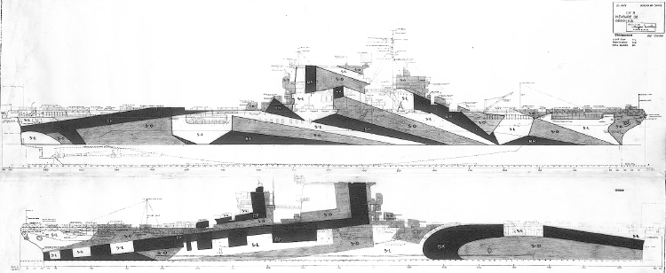
Official US Navy drawing for Ms. 32.11a. Photos indicate that yard personnel matched this drawing very closely. They did a great job.

Official US Navy drawing for Ms. 32.11a. Photos indicate that yard personnel matched this drawing very closely. They did a great job.
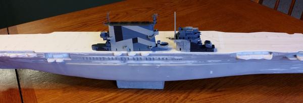
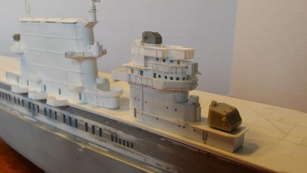
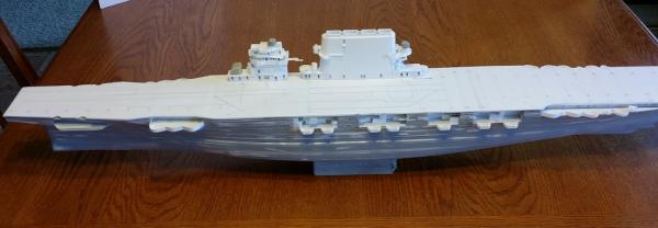
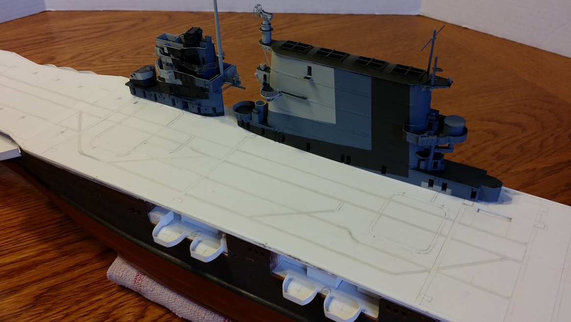
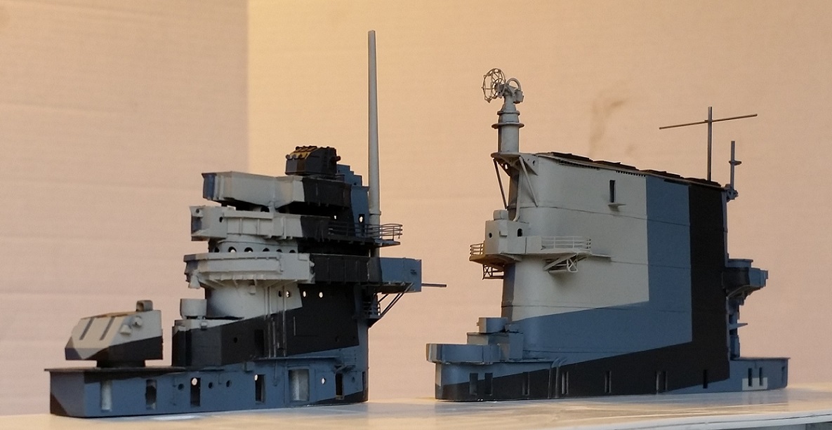
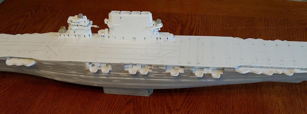
An overall view of the model so far. The colors are not lightened for scale effect and appear a bit dark. In this scale, it is less necessary than for 1/700, but will help. I'll do that through weathering techniques. I decided this would be best since Saratoga only wore this scheme for some weeks before it was painted out. Therefore, it should look rather new and stark with only mild weathering and no fading.

Dull black needs some adjustment, but pretty close. The lower section of the foremast is installed. The foremast is an Evergreen styrene tube filled with and Evergreen styrene rod, and tapered on each end by turning in a drill against some fine sandpaper. It leans forward a bit here but that will be fixed later.
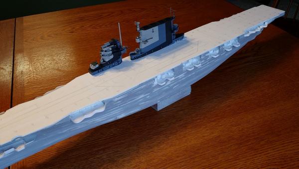
The dull black on both conning tower and funnel needs some adjustment, but you get a feel for how the pattern looks. When painted, the flight deck will be overall blue, replicating a stained appearance, with black numeral "3"s at each end. When set next to a 1/350 scale Trumpeter Yorktown for comparison, Sara's flight deck looks decidedly narrow, lending to her fast look. In practice, I imagine that an Essex class flight deck was much more practical because of its wider size and more uniform shape. But I just love the look of this ship.

Details of the SM radar dish show up pretty well in this photo. You can also see that the barbette for the Twin 5-inch mount by L'Arsenal needs to be enlarged and moved forward. The L"Arsenal gunhouse itself looks very good. The bell-shaped object suspended from the front of the Navigating Bridge venturi is, yes, the ship's bell, filed and hollowed out from some stretched sprue to match drawings.

-
Thank you all very much! I appreciate the encouragement and interest.
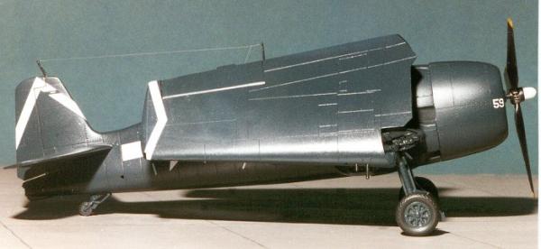
Some good questions asked. For aircraft, rather than make them from scratch, I intend to modify 1/350 scale Hellcats and Avengers made in plastic by Trumpeter. Overall, they have good outlines and shape but need detailing and some minor corrections for better accuracy. At the time Saratoga wore camouflage, she operated primarily out of Pearl Harbor conducting pre-deployment training exercises for various airgroups not assigned to Saratoga. So those aircraft will not have Saratoga's distinctive airgroup markings (white chevron and white propeller hub).
The ship's camouflage scheme was repainted overall Navy Blue 5-N before deploying back to the South Pacific for combat operations.
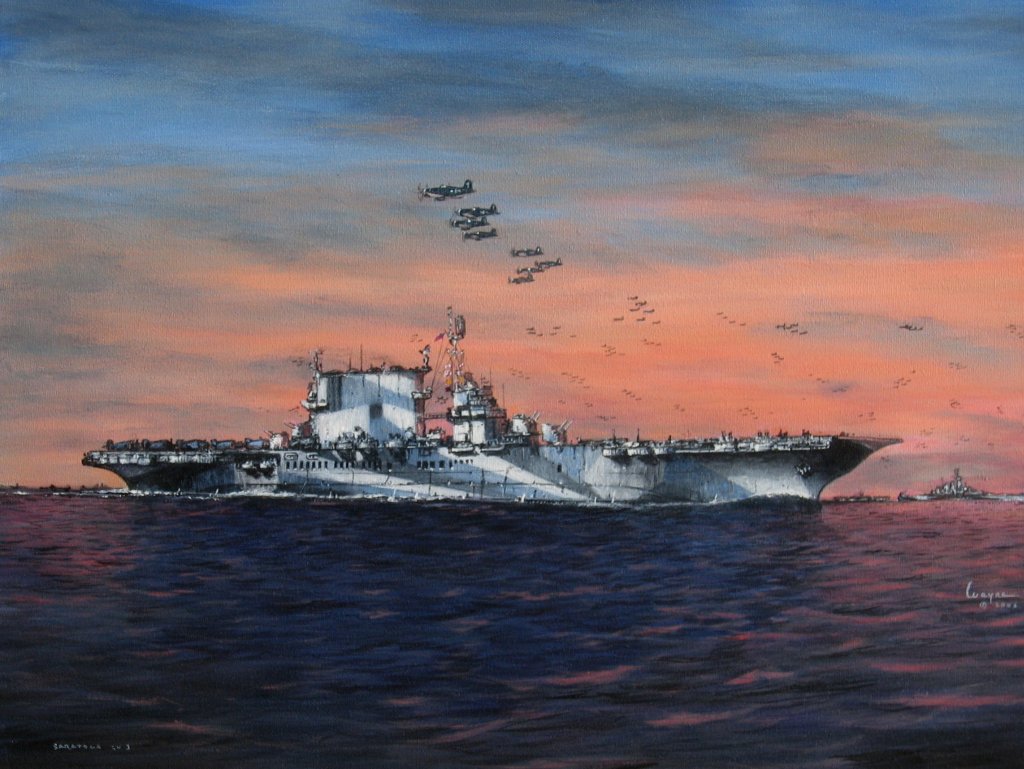
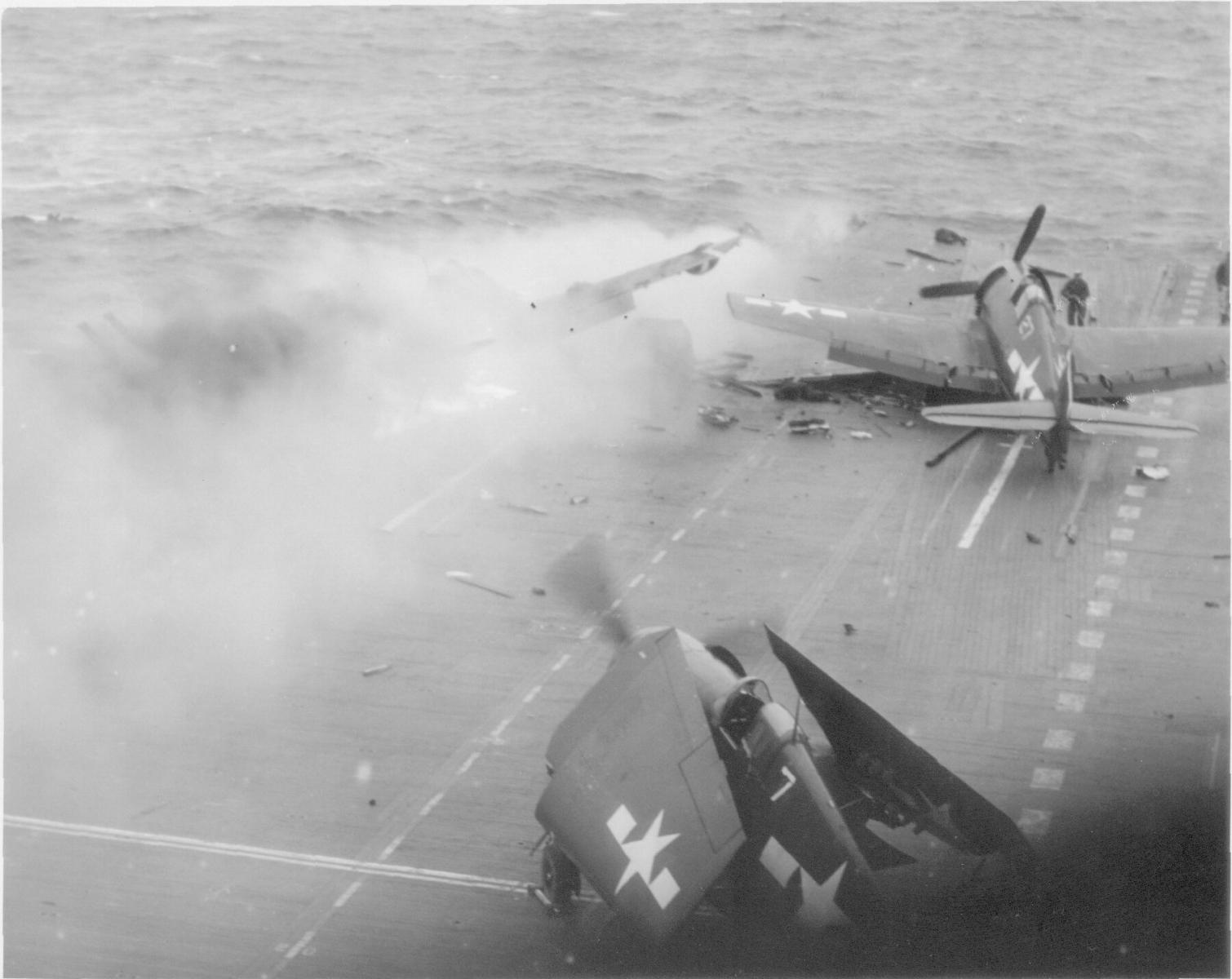
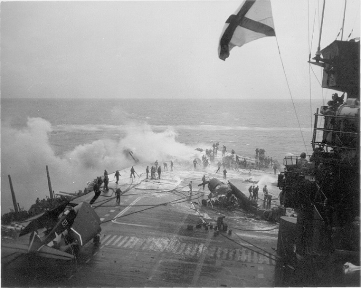
Here are two photos taken of Saratoga during Kamikaze attacks showing Hellcats in the markings of her airgroup, and a 1/48 scale model of an F6F-5 Hellcat made by modeler Scott Van Aken in Saratoga's markings. Sadly, the Hellcats seen in the top photo are about to be obliterated by another Kamikaze striking this area shortly after this photo was taken.

In the photograph below, the Hellcats seen in the above photo have been destroyed by another Kamikaze crash (5 hit the ship in close succession that day). Very little remains of Hellcat #7, seen in the photo above, and Hellcat #27 and the night-fighting Hellcat that was burning to its left are both gone entirely. Note the white outline on the flight deck in the shape of an elevator forward of the island. This outline is meant to be deceptive; it is a false elevator outline. Kamikazes were known to target elevators in an attempt to render the ship incapable of operating aircraft even if the ship survived the attack. The false markings provide for a decoy, away from the actual elevator which was farther aft of this point, and the hangar deck below.

Although some of the fittings and all of the aircraft will not be scratchbuilt, I still consider the ship itself to be scratchbuilt in the same way that a cake made from scratch doesn't require the baker to grind the wheat or mill the sugar.
very nice build here Steve......the level of detail is fantastic! I noticed the different color in plastic.......are you using some parts from a kit? looking forward in seeing more

The darker items are resin aftermarket items from L'Arsenal of Normandy, France. They are a Twin 5-inch/38 caliber mount and a Mk.37 5-inch Gun Director. These items look very good in this scale.
They will each have to be modified for accuracy. Saratoga had two Mk.37 Directors with angled-backs of an early design. The Directors shown here are the latter flat-back type. Modifying them will be a matter of simple cutting and the relocation of a small boxy structure.
Saratoga carried four Twin 5-inch Mounts, two forward of the conning tower and two aft of the funnel. The base of L'Arsenal's Twin 5-inch Mount is too small and should be positioned a bit more forward rather than centered front-to-back. The modification needed will be replacing the base with a new, scratchbuilt one of proper size and position. When complete and installed, the mounts' bases will sit directly over the interior barbettes you see in the photos above.
-
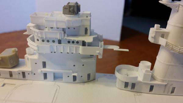
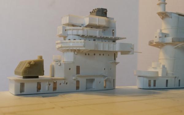
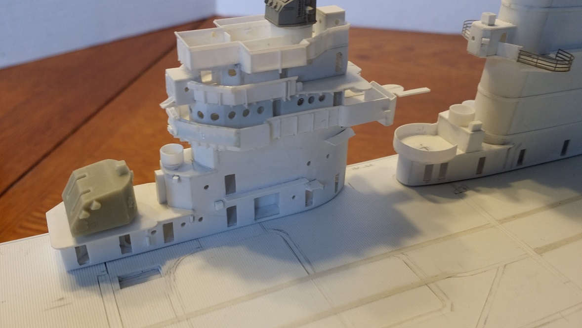
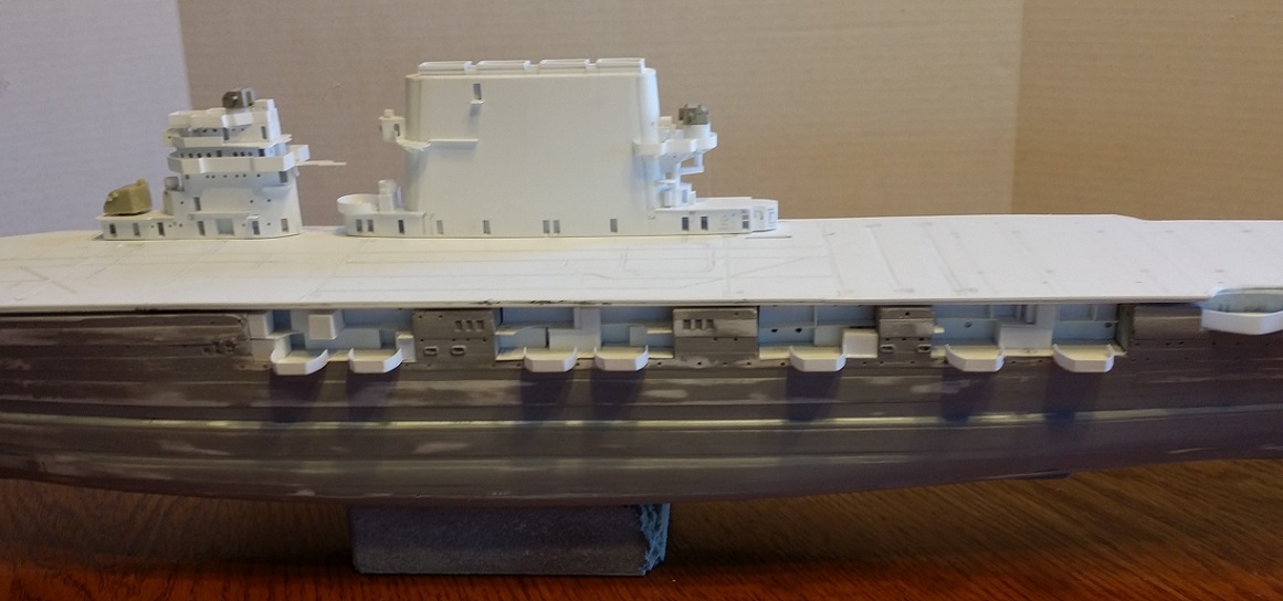
More detailing done to the conning tower. The venturis and splinter shield vertical reinforcing ribs have been roughed in. They still need some tweaking but look good so far.
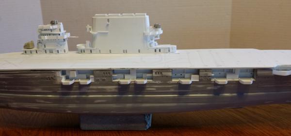
Saratoga in 1944 had venturis on two levels of the conning tower. 1) The venturi on the flag bridge above the pilot house was rather plain. 2) The venturi forward of the pilot house was an elaborate design consisting of a simple venturi placed above a wind splitter of several compound curves.Port side. Photos of the ship during its 1944 refit show that the vertical reinforcing ribs on the splinter shielding are uniformly spaced on the navigating bridge level (pilot house level) but not along the splinter shielding of the two levels above. The rectangular cutout in the flight deck is the bomb elevator opening. The cross-deck strip with two grooves appearing as a set of three wide planks replicates the crash barrier's metal strip with two parallel recesses for the crash barrier's cables. Looking into the open hatches under the twin 5-inch/38 mount, interior bulkheads, oriented radially from the interior barbette, and scuttles are visible.
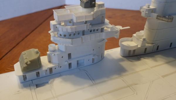
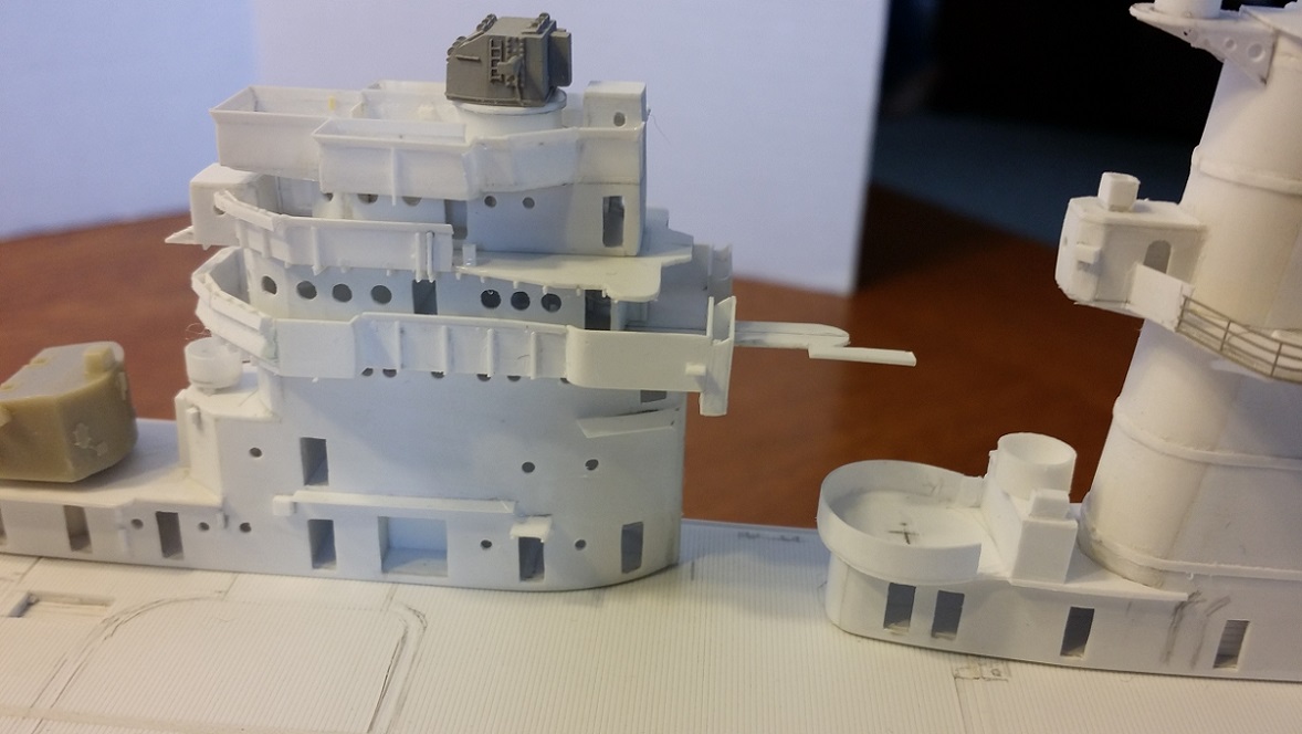
The complex shape of the two-part venturi forward of the pilot house can be seen well in this photo. Notice that both venturis are open. The flight deck planking shows up well in this photo. Another crash barrier strip appears here, located at the base of the funnel, complete with parallel cable recesses, extending cross-deck.
Some of the supporting structure under the decks can be seen here. Looking under the SM Radar Platform extending forward from the funnel cap, the platform's supporting structure is visible, all consistent with photos.
Starboard side. Photos and plans of the conning tower show that features such as porthole placement, hatch locations, and splinter shield ribbing are not the same from port to starboard. The conning tower is generally symmetrical in shape but not in detail.
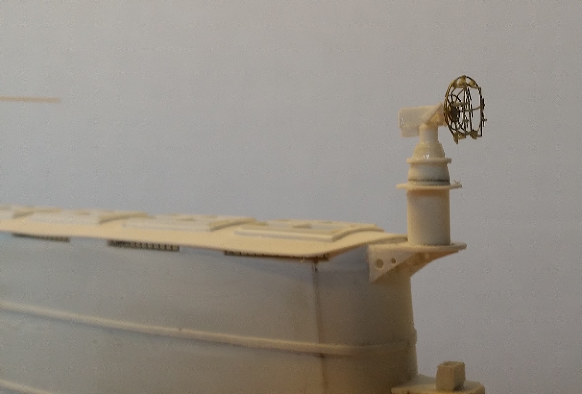
The SM radar dish is a Gold Medal Models SP radar dish that perfectly matches photos of Saratoga's SM dish. The dish is composed of four PE parts. The GMM part comes from GMM's Essex set. An SC-3 radar screen is needed to install on a mount at the aft end of the top of the funnel cap. I'll need to procure one as I used the GMM SC screen on a model of USS Yorktown CV-10. Hoping to find a spare SC in the stash somewhere...
-
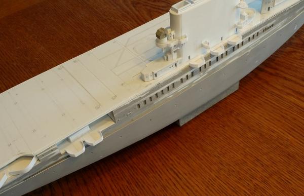
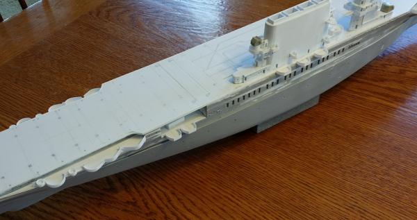
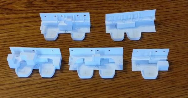
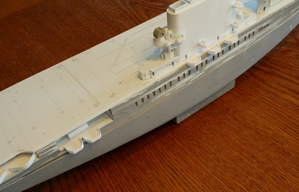
Taking a break from the conning tower and funnel, turning to heavy AA gun positions, here are some photos of initial work done on the 5-inch single mounts' and all but four of the quad 40mm Bofors mounts' positions. (Additionally, there are two twin 40mm Bofors tubs not yet fabricated.)
For the AA positions arrayed within the ship's former boat bays, I've begun fabricating these multi-level structures as inserts. Although not yet complete, the major structures, composed mostly of 40mm ammunition clipping rooms and vents on the actual ship, are visible.
The splinter shielding, not yet complete, is composed of 0.010" styrene strip. It will receive outboard vertical stiffeners later and the tubs will receive supporting girders/trusses where indicated in plans and photos.
Note also that the portholes on the bulkheads at the back of the bays are shown quite large in plans and photos so I have assumed them to be standard 16" ports. By comparison, the portholes in photos and plans along the hull's shell plating are probably the smaller 12" standard US Navy ports so I have sized them accordingly.Aft 5-inch and Bofors platforms are located at a level equivalent with what would be the gallery deck on later carriers. This siting of 5-inch mounts is quite high compared to later classes (Yorktown and Essex). When the AA guns are set in place, their tops will be nearly flush with the flight deck.
It would be interesting to know whether this height made crewmen and aircraft on the flight deck vulnerable to blast effects from mounts sited here, and mounts vulnerable to damage from aircraft accidents. Various publications indicate that these damage vulnerability problems were among the considerations in the siting of 5-inch mounts well below flight deck level in Midway class ships. In the Yorktown and Essex classes, the flight deck was a deck higher than Saratoga's flight deck, and the 5-inch single mounts were sited a deck lower than the gallery deck.

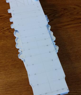
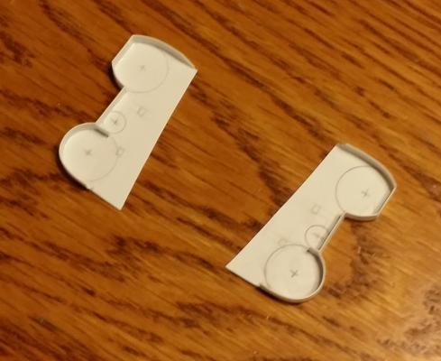
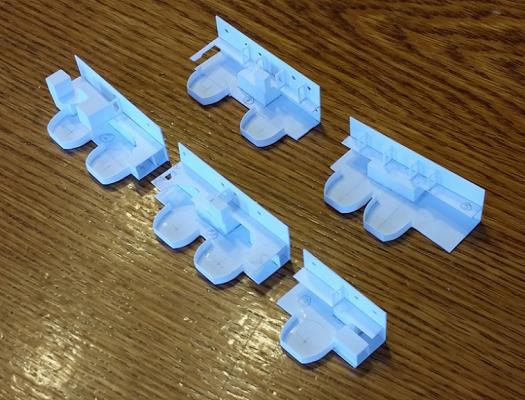
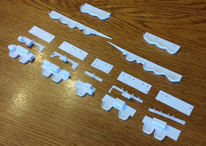
Work on the two remaining quad Bofors platforms has begun. The penciled larger circles are the Bofors tubs. The smaller circles mark the locations of future director tubs. The gentle curves of each platform are where the platforms conform to the side of the hull.
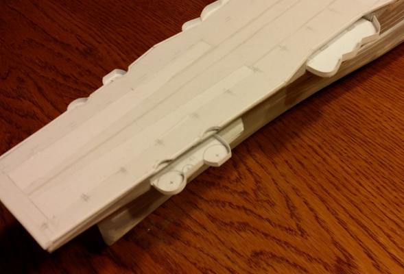
Here's where those Bofors platforms go, on hull sponsons right up near the bow. Cutouts, seen in the flight deck, will be cut into the hull soon. The sponson's rearward extension is a paravane platform. There is another mirrored on the starboard side sponson identical in shape. There are just two more Bofors platforms to construct: two twin mounts were positioned in individual tubs on the port side of the ship forward of the boat bays.
-
Taking a break from the conning tower and funnel, turning to heavy AA gun positions, here are some photos of initial work done on the 5-inch single mounts' and all but four of the quad 40mm Bofors mounts' positions. (Additionally, there are two twin 40mm Bofors tubs not yet fabricated.)
For the AA positions arrayed within the ship's former boat bays, I've begun fabricating these multi-level structures as inserts. Although not yet complete, the major structures, composed mostly of 40mm ammunition clipping rooms and vents on the actual ship, are visible.
The splinter shielding, not yet complete, is composed of 0.010" styrene strip. It will receive outboard vertical stiffeners later and the tubs will receive supporting girders/trusses where indicated in plans and photos.
Note also that the portholes on the bulkheads at the back of the bays are shown quite large in plans and photos so I have assumed them to be standard 16" ports. By comparison, the portholes in photos and plans along the hull's shell plating are probably the smaller 12" standard US Navy ports so I have sized them accordingly.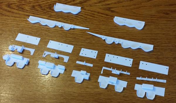

- qwerty2008, GrandpaPhil, hexnut and 2 others
-
5


LPH-11 USS New Orleans by Spaceman Spiff - FINISHED - Iron Shipwrights - 1/350 - RESIN
in - Kit build logs for subjects built from 1901 - Present Day
Posted
Just let me know how many sets of 3 you need and I will add them to your existing order. I'll have PayPal send you an invoice.
Thanks so much!