


Roger Pellett
-
Posts
4,519 -
Joined
-
Last visited
Content Type
Profiles
Forums
Gallery
Events
Posts posted by Roger Pellett
-
-
-
-
-
Simon,
You do have a drawing board, the plywood sheet that you are using to cut the bulkheads. I would suggest that you visit an office supply store (Stationer?) to buy an inexpensive French curve. You can use this to draw your bulkheads without “jiggles.”
On a broader note, you are trying to transform a 2D drawing into a 3D object. 250+- years ago shipbuilders developed the system of “Lofting,” to solve this problem. Lofting involved redrawing the ship’s entire lines drawing full sized on a large flat floor. The purpose was to check all views to ensure that everything matched. This would ensure a fair hull; one with smoothly flowing lines. Full sized patterns for the various structural elements could then be developed from the lines drawn on the floor. Note that every time that the lines drawing is redrawn, including the lofting process, subtle changes in the hull’s shape occur, as the draftsman or loftsman adjusts things to ensure that the 3D hull will be fair. There is, therefore, no “definitive” model of an old wooden ship as each draftsman’s interpretation will be slightly different. CAD does not eliminate this issue. It just means that the computer is making these adjustments. In your case, you are making bulkheads without doing the lofting. This will likely cause problems throughout your build.
So, what to do? First of all, start with a good set of drawings that you are not trying to expand with a computer printer. A set of lofted drawings exists in the MacGregor archives. I believe that they can be bought from the SS Great Britain People. If CAD is your thing, get the drawing scanned and lift and print the bulkhead shapes. If like me, you are not interested in using CAD trace the bulkheads directly from the drawing using your French curve. Tracing half a bulkhead and folding it to cut it is fine. An architectural printing house that makes contact prints, not photographic prints can make copies and even change the scale. Making smaller scale copies from large scale drawings is preferable to going the other way as minor drawing errors are reduced rather than expanded.
Roger
-
Kevin, Not sure that I understand the “hatch question” but possibly this helps-
In cases where cargo holds were located below other spaces, access was provided by “cargo trunks.” These were shafts passing from the hatch through the upper space into the hold. Cargo would be lowered down the shaft and then manhandled into position in the hold. I can understand why these might be necessary in passenger vessels where owners did not want to waste upper level spaces by filling them with cargo.
Roger
-
-
-
Very nice work, Dan!
Roger
- Keith Black, Canute and mtaylor
-
 3
3
-
If you look at the mechanics of a lever, I believe that the single/double bank issue is like gearing in a car. Boats intended to travel at high speeds benefited from two oars per thwart. On the other hand, heavy workboats like longboats and launches benefited from the added leverage gained by one oarsman per thwart using the breadth of the boat to gain leverage. At least that’s how I arranged thole pins in my Longboat model.
I also see no reason why these boats could not have been converted back and forth from single to double banked and vice versa as needed as thole pins could be added or removed from holes in the gunwales.
In researching these boats carried aboard warships IMHO there are many details that we know little about.
Roger
-
It is also interesting that they don’t tell you where
she is, although maybe the owner figures that after spending $100,000+ getting her where you can use her is just loose change.
I also cannot imagine that anyone would buy her prior to a survey. These repairs/rebuilds often involve building a completely new boat.
Roger
- Keith Black, mtaylor and thibaultron
-
3
-
A suggestion for building the hull of this demanding model. I would add carved wooden blocks to help define the shape of bow and stern. At the bow, the planking can run over a carved block at either side of the keel. The stern is more problematic. You might want to terminate the planking by running it into into a rabbit at the forward end of a carved stern block.
Roger
- Keith Black, mtaylor and Scottish Guy
-
3
-
-
-
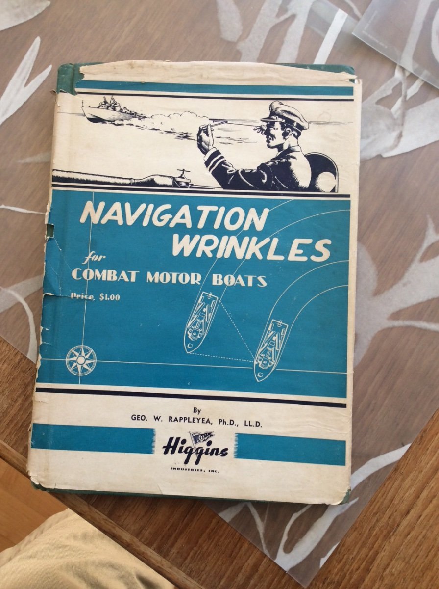
I was about to donate this book to our library’s used book sale but decided instead to offer it to someone who might appreciate it.
The title of the book is Navigation Wrinkles for Combat Motor Boats and it was published during the war by HIGGINS INDUSTRIES. It was apparently supplied to PT Boat crews. The book is exactly what the title says. It is not a modeling guide for PT Boats but as an authentic piece of PT Boat lore would go nicely with a model.
Price: FREE delivered by US mail to a US destination.
If you want it send me a PM and I’ll put it in the mail.
Roger

-
-
-
Kevin,
There seems to be two questions here:
1. Can you produce an accurately shaped hull using just the information on the drawing that you posted?
Answer- No you cannot. The drawing does not provide enough information. In addition to the shape of the midships section, you need more hull sections both fore and aft.
2. How to design a series of ships’ boats to allow scaling up and down as needed.
Answer- Difficult. First of all what you want to do is highly dependent on period. The hull shape of a boat for Cutty Sark is much different from that of 100 years earlier. For that reason Whole Moulding is inappropriate for a late Nineteenth Century vessel.
It might be possible to design a series of “Lifeboats.” Only one boat in the photo that you posted, the double ended one is a lifeboat. As I posted above these boats were designed to meet Board of Trade Rules, and post Titanic SOLAS rules. The starting point was human capacity, specified to be 10 cubic feet per person. The overall dimensions of the boat were then determined using the formula: (L*(4A+2B+G))/12
L= Length In feet
A= Area of forward quarter length section
B= Area of midship section
G= Area of aft quarter length section
This formula provides the boat’s available capacity in cubic feet. This capacity must be greater or equal to the number of people X 10 cu ft per person.
This still does not determine the shape of the boat and this is not entirely up to the designer. The book, Ships’ Boats by Ernest W. Blocksidge c1920 provides additional rules for hull shape, stability, and strength.
You need to solve a Naval Architecture problem, not a computer problem.
Roger
-
Ship’s boats, naval and otherwise are a particular interest of mine.
On a sailing ship like Cutty Sark, all of the boats that she carried were not “lifeboats.” She would have carried one or more transom sterned workboats for ship to shore service while in the harbor. Actual lifeboats, number and design, carried by British Flagged vessels were governed by British Board of Trade Regulations. I have a book published in the 1920’s that provides detailed design information for lifeboats meeting Board of Trade rules. The name of the book is Ships Boats. I’ll post the author’s name later.
The National Maritime Museum’s Branch in Falmouth (UK) recently built a replica of one of Titanic’s lifeboats. I visited the museum in 2018 and talked to the boatbuilder. He told me that they had been unable to find any drawings for the actual boats carried by Titanic. The hull lines, the drawing that you need to determine the shape of the hull formers, were based on a drawing from an old technical paper. I’ll post a copy later.
The size of a lifeboat was determined by the number of people that it was supposed to carry. This determined cubic capacity: Length x Width x Depth x A Factor. True lifeboats tend to have similar characteristics, whether very large like Titanic’s or much smaller ones that would have been carried on a ship like Cutty Sark.
Roger
-
I’m afraid in my workshop practices I’ve never lost the “beat to fit” mentality from building things as a teenager! Cutting the glass ahead of time and then building the case to fit it is great idea.
Roger
- mtaylor, Ryland Craze and Bob Cleek
-
3
-
Bob Cleek’s post is right on. If your workshop includes a full sized table saw glass cases are not difficult to make. I rip the wood from hardwood stock, my favorite is American Black Walnut. I have a set of “vintage” Sears Molding cutters that fit on my table saw. I have never had good results with a router. The glass groove is made with a regular table saw blade. My cases are not works of art, joints are simple 45 degree miters.
Unlike Bob, I have not felt the need to use UV resistant glass, but I don’t live in sunny California😁. I take careful measurements and let someone else cut the glass. Cut single strength glass from Ace Hardware was inexpensive.
Roger
- Cathead, Bob Cleek and Ryland Craze
-
3
-
Were Optimists always fiberglass or were the early ones wooden?
Roger
-
-
I believe that the Mariners Museum in Newport News VA owns the plans from the Chris Craft Archives.
WoodenBoat Magazine also sells planks for a “Chris Craft type” runabout. Since you live in Korea I believe that WoodenBoat can provide Ecopies to download.
Ron is right. Use actual builders plans .
Roger
- modeller_masa, Canute and mtaylor
-
3
-
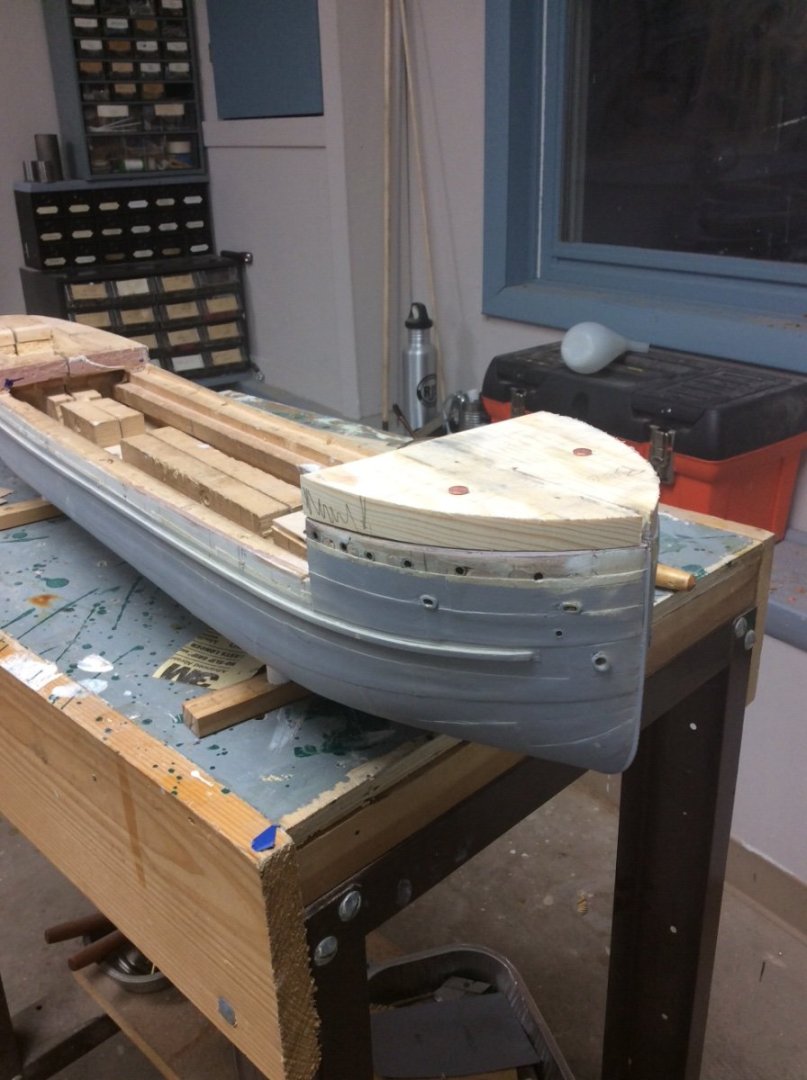
Since my last post I have been trying to complete the poop deck assembly for the ship. It seems like every time I make some progress, I have to take a step back to fix a problem.
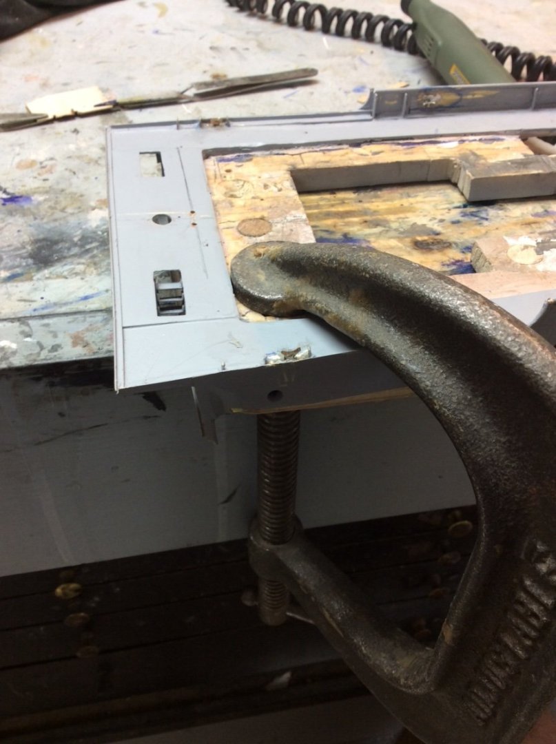
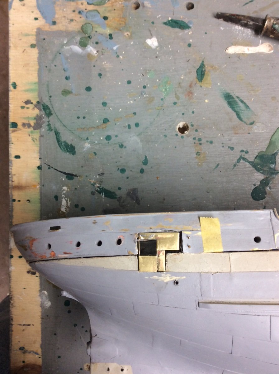
The first step was to join the poop deck assembly to the bulkhead. This was a simple matter of soldering the two deck edge angles to the brass deck plating. The next step was to locate and drill the many holes for attaching the fittings to be later installed on the deck.
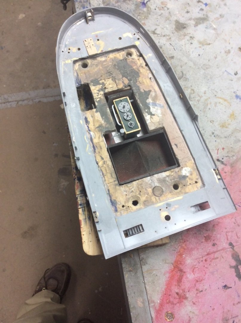
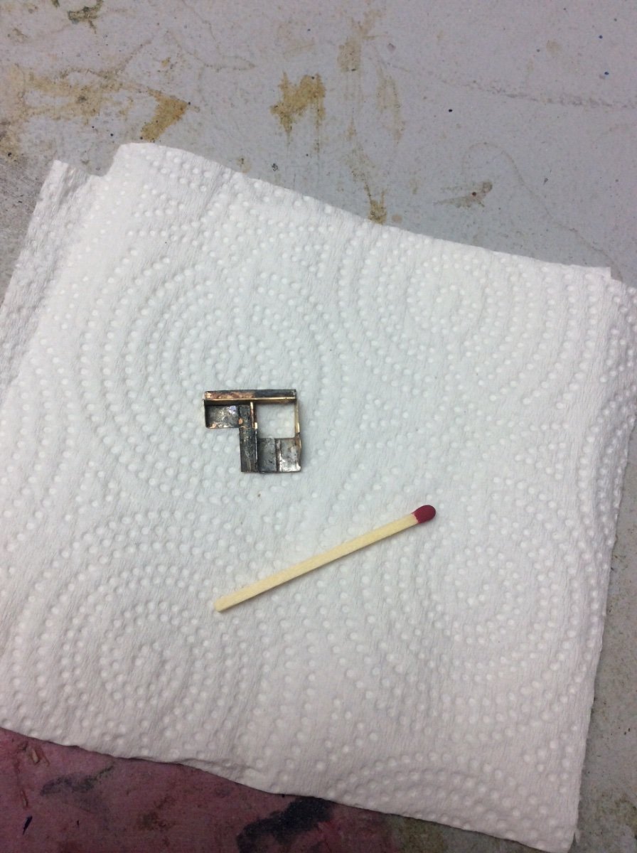
There is an an opening in the center of the poop deck stern rail. This could be used to tow another vessel or to assist in docking the ship itself. Since this could transfer considerable loads to the poop deck fantail rail the general arrangement drawings show a reinforcing structure. Although there is a plan view of this there are no elevations shown. The structure shown in the photo is my best guess of what it might have looked like.
Photos of Great Lakes ships in the lumber trades often show them with long wooden fenders. These were a baulk of square or round section timber hung from one end over the side of the ship. A rope was attached the other end to allow the fender to be hauled up when not in use. This was before the time when old tires were available. Although photos do not show them in use, Benjamin Noble was fitted with chocks and cleats for four of these fenders per side. One chock and two cleats per side are located on the poop deck. The chocks, shown in the last post, were easily epoxied into holes. Likewise the cleats were soldered onto the inside of the bulwark or to the deck plating.
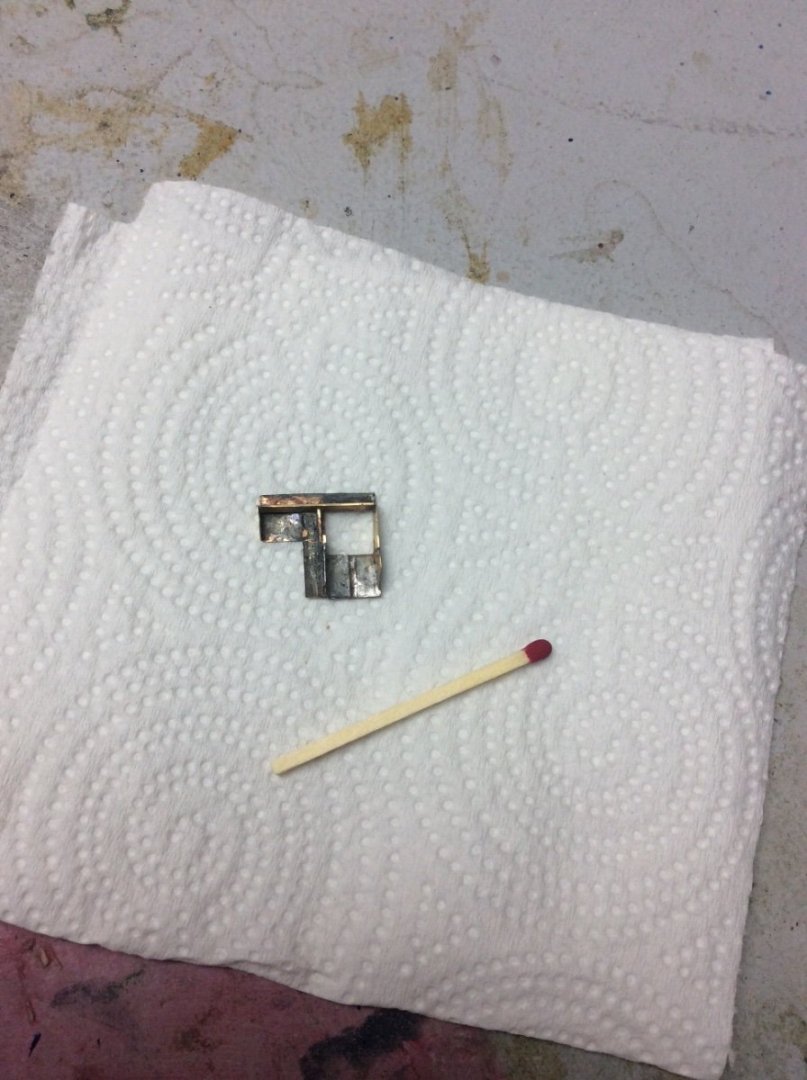
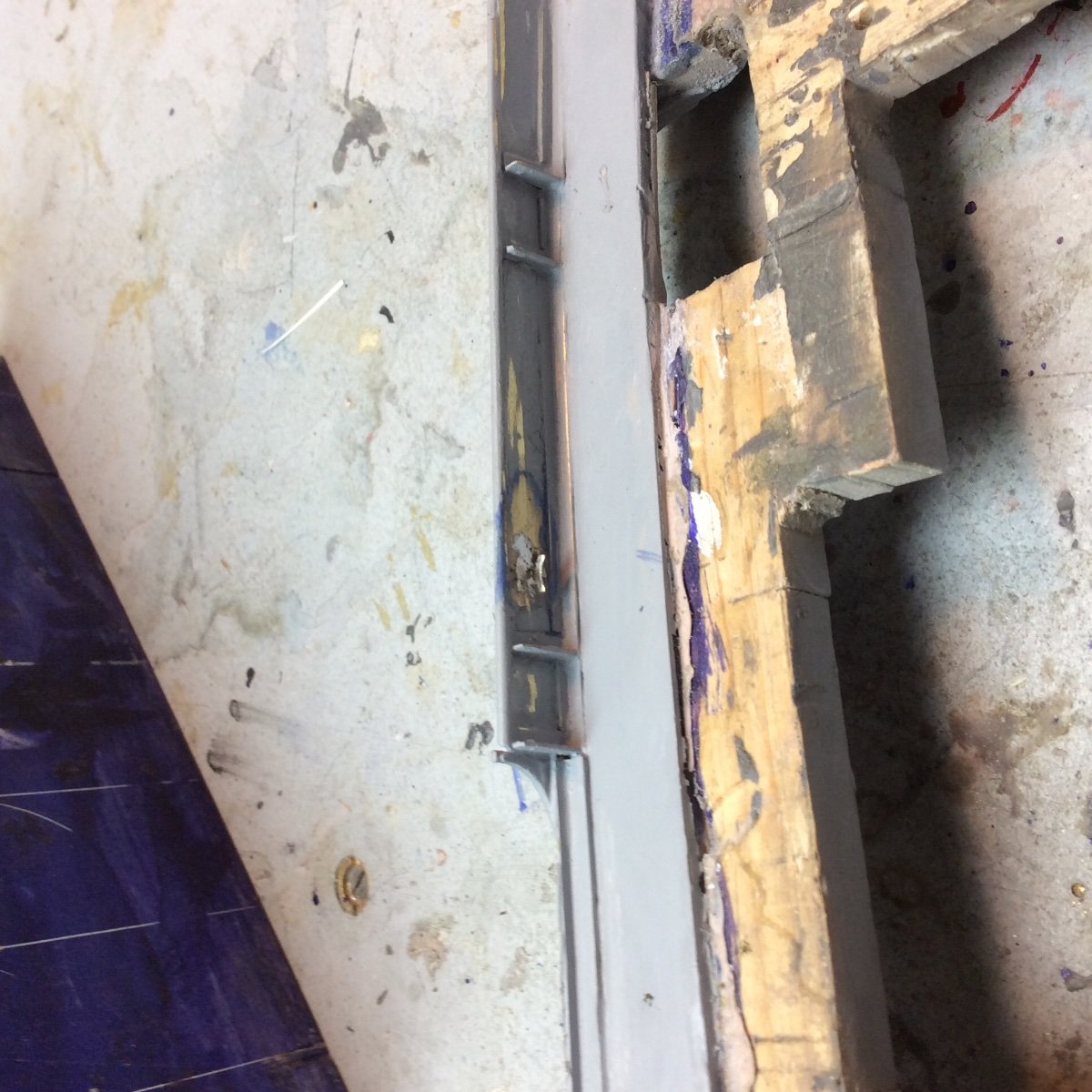
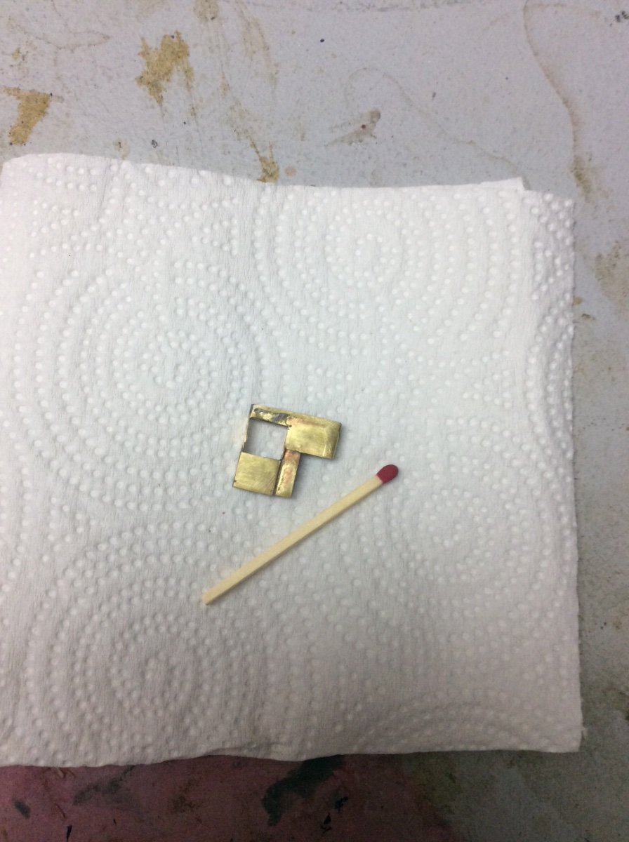
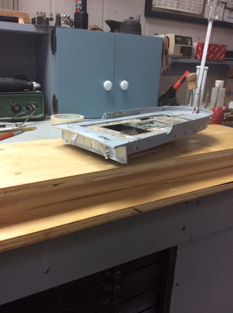
Just when I thought that the assembly was finished I noticed that the brass plating around the gangway door had pulled loose. This has been a problem area ever since I decided to show the upper half of the gangway door open as is often the case with Great Lakes vessels sailing in fair weather. Rather than patching things up I decided to bite the bullet and to fabricate a proper door frame. The resulting frame made from soldered brass was then epoxied into the hole and the whole thing faired with Bondo. The door frame assembly includes the bottom (closed) half of the gangway door that fits into the hull when the poop deck and hull assemblies are joined.
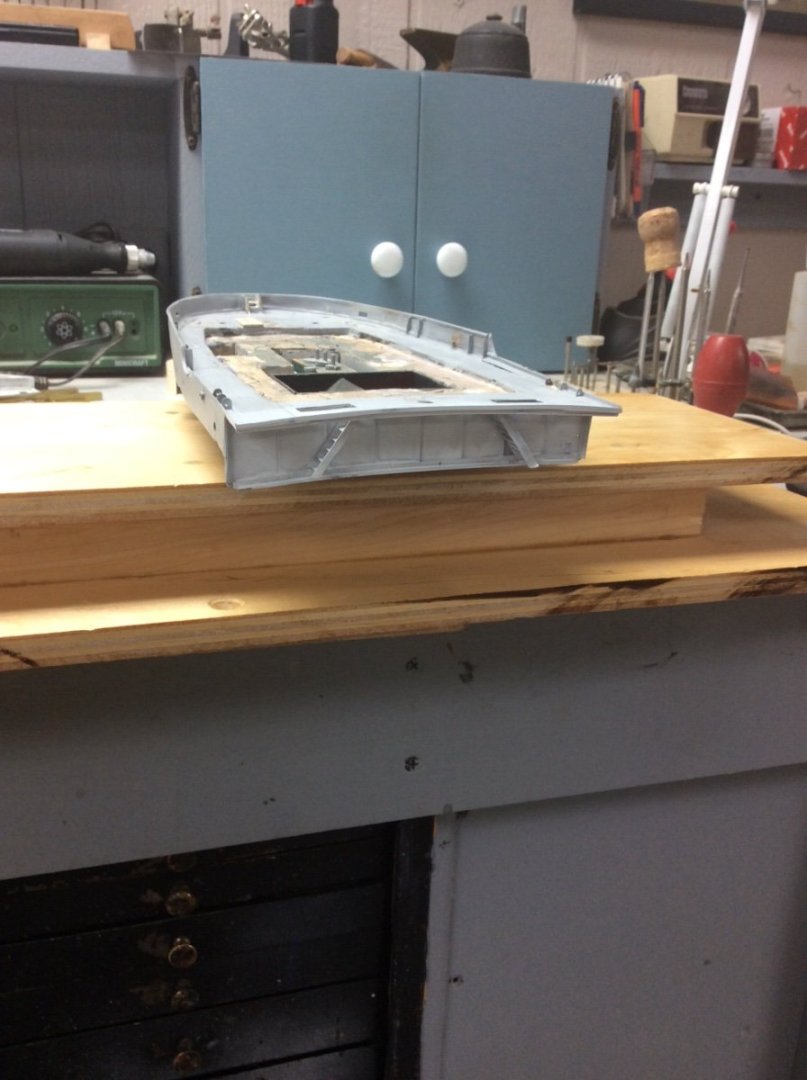
Cleaned up and coated with primer the poop deck assembly is finished. Whew, a major milestone!
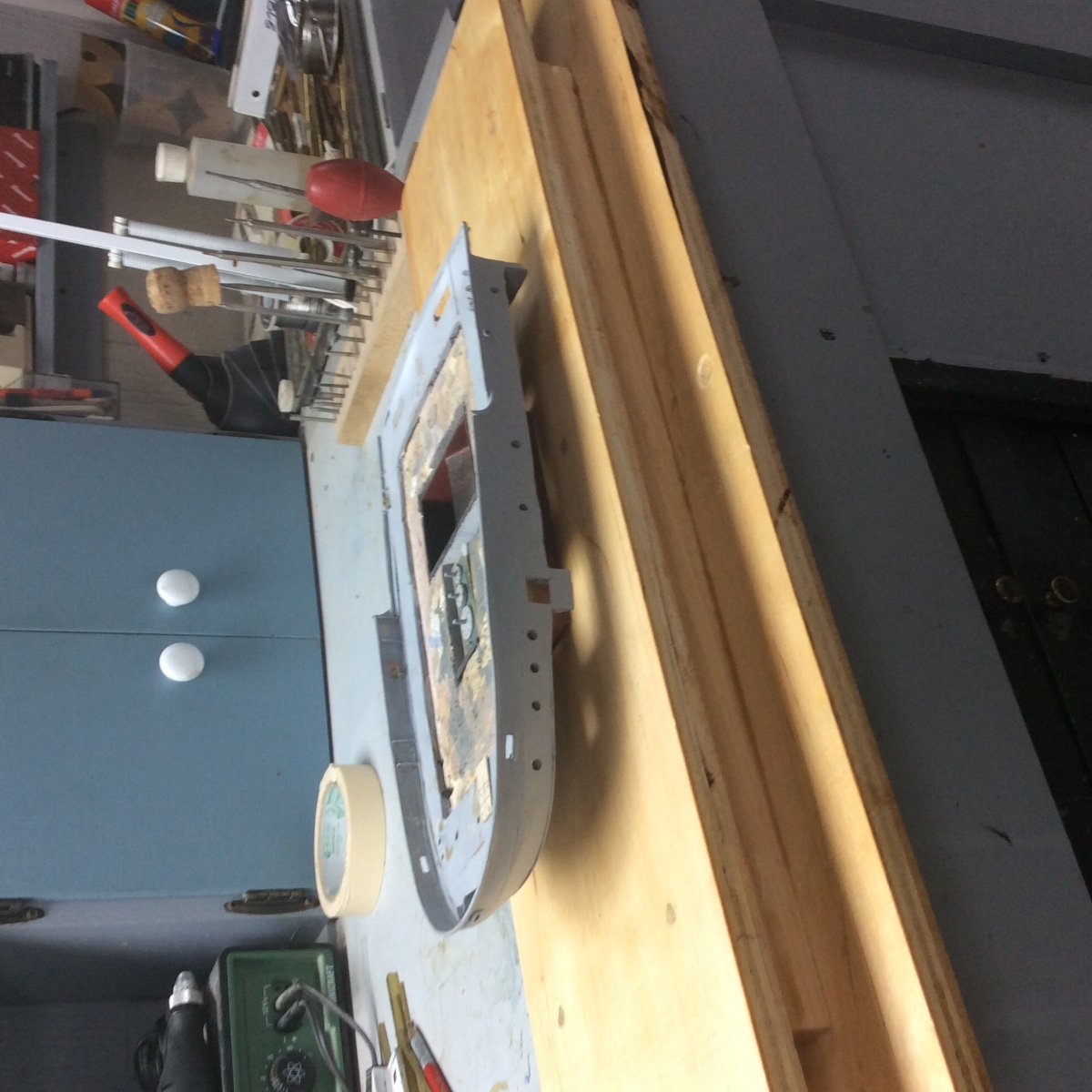
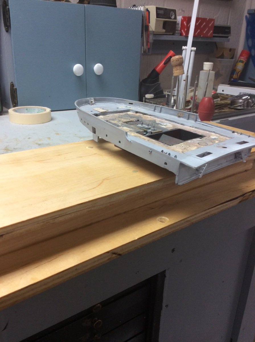
Next is the fabrication of the forecastle rail, deck, and bulkhead.
The last photo shows the wooden former for this. Since the assembly must mate with the hull the former is upside down.
Roger


- mbp521, TBlack, Keith Black and 12 others
-
15


USS Cairo by Cathead - FINISHED - BlueJacket Shipcrafters - 1:192
in - Kit build logs for subjects built from 1851 - 1900
Posted
Ouch! Hatchet and axe injuries are scary. Good to hear that you have recovered your dexterity.
Roger