


Roger Pellett
-
Posts
4,519 -
Joined
-
Last visited
Content Type
Profiles
Forums
Gallery
Events
Posts posted by Roger Pellett
-
-
Great photos of a rarely seen piece of equipment!
- Canute, mtaylor, thibaultron and 1 other
-
 4
4
-
Old tools are often a good buy if you’re at the right place at the right time. The trailer was nice too. It had been built as “Government Work” at the nearby Duluth, Messabe, and Iron Range Railroad maintenance shop. It had detachable racks for hauling four canoes. Unfortunately my wife and the next door neighbor lady quickly got tired of seeing it parked outside so I donated it to the fund raising auction for our local sailing assn.
Roger
- Keith Black, mtaylor, mbp521 and 1 other
-
4
-
From the first two photos that you posted it appears that the bulkheads are too widely spaced to properly support the planking and to properly define the shape of the hull. How to proceed?
Decide to push ahead and build the model- As Johnny suggests you can glue blocks between the bulkheads, then carve them to produce a fair hull. Then plank the resulting solid hull. You will wind up with a model, but probably not America. George Steers, America’s designer was a talented Naval Architect and his hull forms, particularly the sterns, are distinctive and beautiful. I doubt if even a highly skilled model maker could duplicate America’s hull form with this kit.
Trash the kit- Building a beginner kit is certainly good advice. Both Bluejacket and Model Shipways offer these. BUT! The kit needs to hold your interest. If there was a compelling reason that you wanted to model America, Bluejacket offers two America kits and the company has a good reputation.
Roger
-
If “digital replacement” becomes a selling point, you need to replace that Craftsman full sized table saw with a SawStop table saw. That’s a Rabbit Hole involving $$$$!
My full sized table saw is a 10in Delta Contractor’s saw bought for $150 from a local canoe builder who upgraded to a SawStop. The sale price included a trailer to haul it home! 😁
Roger
- FriedClams, Canute, mbp521 and 2 others
-
5
-
Our hobby involves handling tiny parts. As we get older, this gets harder as our hands get less steady and, at least in my case we loose feeling in our finger tips. Rigging blocks top the list of this as sometimes handling them is like trying to grip a watermelon seed.
To help me, and to minimize things lost to the Floor Gods, I have learned to minimize the number of “moving parts.” This means whenever possible securing parts, however small, in some sort of vise or fixture. The last time that I did rigging, I built a small simple rigging vise that gripped a block in an alligator clip. The head of the vise that held the block was a piece of aluminum that slid up and down on a steel rod, and was secured by a set screw. This allowed the block to be fixed at eye level, with me seated. A purchased fly tying vise would have worked too.
Wherever possible, I clamped the block in the alligator clip, brushed a tiny dab of clear fingernail polish on the end of the line, and poked it through the hole in the block. Sometimes it helps to trim the end of the stiffened line with a pair of SHARP scissors to get rid of loose threads that might interfere with threading the block. When I finished the model I put the scissors away until the next rigging job.
Roger
- thibaultron, mtaylor and Ryland Craze
-
3
-
Before I began to buy dedicated ship modeling tools, I outfitted my shop with full sized hand and power tools. This is true for two of my vises. I have a very large machinist’s vise and a carpenter’s vise mounted under a workshop top. Like a Jaager and Bob, I have never felt the need for a dedicated keel vise. In fact, it se me to me that clamping a model by its keel is courting disaster. An unintentional knock or even forces applied to build the model and the keel is broken.
Save your money to buy real tools.
Roger
-
I used silkspan to make furled sails for my Longboat model. Here’s how I handled it:
I built a wooden frame and taped the silkspan to it. I used regular blue painter’s tape and taped it continuously around the frame.
Next, I sprayed the silkspan with water. I used a spray bottle, Not a squirt bottle. An airbrush would have worked just as well. The next day the silkspan was drum tight.
I placed the frame with the silkspan over a wooden plug. I put a piece of wax paper between the plug and the silkspan.
I rolled a coat of acrylic paint onto the silkspan using a short, small diameter foam roller.
The coated silkspan could then be cut from the frame to make the sails.
This scheme avoids the need to handle loose pieces of wet silkspan.
Roger
-
Hi Keith,
Hopefully tomorow I’ll be able to take the saw blade off to see the description. It needs to be cleaned as it’s not cutting well. The Byrnes saw blades, at least for me, are not easy to change. So, I’ve been putting it off. Then I have to decide whether to put it on backwards!
Roger
- mtaylor, Cathead, FriedClams and 3 others
-
6
-
Several years ago the Nautical Research Journal published an article about a model of USS Arizona built for the visitors center at Pearl Harbor. A good bit of the article involved her surprisingly complex paint scheme at the time of the attack. It seems that there is debate even for this well documented major warship sunk 81 years ago.
The chances of finding a definitive paint scheme for a small vessel that sailed 270 or so years ago would seem to be nonexistent.
Roger
- Canute, Charles Green, mtaylor and 4 others
-
7
-
I like working with brass. I find copper too soft and in fact don’t anneal the brass for the same reason. I was concerned about the longevity of plastic. When I started the model, I was not familiar with Bakelite coated paper. I also avoid anything that requires use of CA glue as I am allergic to it.
Roger
- Canute, mbp521, Keith Black and 4 others
-
7
-
The very first issues of the now defunct magazine Model Shipwright featured a series of articles by the South African model builder Bob Litchey (sp?) about building a model of Grenado. I am quite sure that this is the same model that Allen posted above from the RMG collection. It dates from c1975.
Roger
-
Eric, Thanks for the kind words.
As you well know from your stunning riverboat models, a good and sometimes lengthy part of scratch building is figuring out how to build things. This often requires building something several times to get it right. I am also not one of those people who can render the entire ship in CAD, virtually dissemble it, and build to print. I do not have these abilities. Each part, becomes a separate model. Working from builders plans rather than “Model makers plans” also slows things as information must be assembled from several sources. Yesterday afternoon was spent laying out windows, doors, and ladders on the after end of the forecastle bulkhead to make sure that everything would fit. Hopefully, I can continue to maintain interest and not get sidetracked.
As the Noble was a steel ship, I feel that metal in the end will provide a more realistic model. Brass also provides a number of advantages. At 1:96 scale, 1in equals approximately .01in. A ship like this used little if any plate as thick as 1in. Most plate used in structural applications was 1/2in or less; scale .005in. For the fantail stern bulwark, I used .005in thick brass sheet, and as posted previously, it was too thin to hold up. For the forecastle bulwark I used .005in sheet for the deck which will be epoxied solidly to the wooden hull below but switched to .010 thick material for the bulwark itself. Since both the top and bottom edges of the bulwark are hidden the thicker material is not apparent. It would be difficult for me to fabricate wooden materials as thin as .010 or .005 in.
Brass also provides other advantages. It cuts cleanly, and there is no grain to hide. Like other copper alloys it is easy to solder. Soft soldered joints, either lead-tin or lead free provide adequate strength for a static model. Actually, the most difficult part of soldering is often clamping tiny parts together. I have a drawer full of 1/2 and 3/8in steel brads. I do not hesitate to drive these through the brass deck to temporarily secure small parts for soldering. Later a dab of Bondo will fill in the hole. With a Byrnes saw with a fine toothed blade, brass sheet and K&S square and rectangular tubing can be cut into the structural shapes that were used to build riveted ships. .005in and .010 thick brass sheet can be cleanly cut with ordinary scissors. For long straight cuts I use a guillotine paper cutter.
Roger
- Keith Black, Cathead, mtaylor and 3 others
-
6
-
The months since my last post have passed too quickly. We made a September trip to Southwestern Indiana to visit my son and his family who we hadn’t seen for over a year and also enjoyed Duluth’s beautiful Autumn weather. We have also enjoyed our Michigan Wolverine’s 11-0 football season. Tomorrow’s game with Ohio State will be the real test.
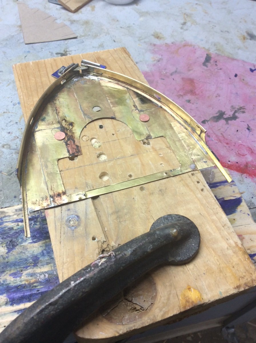
Time in the shop was spent fabricating Benjamin Noble’s forecastle bulwark. Again the material is soldered brass. The process began by carving a wooden former (last photo, previous post). Complicating this process is the need to think “upside down” as the forecastle deck is laid on top of plug and the sides of the bulwark are bent around the sides.
Photo 1 shows the plug. The angle between the deck edge and side shell plating has been bent around the plug and the center deck plate has been laid. The angle was ripped from a square brass tube using my Byrnes saw. Bending an angle is difficult as it always tries to twist. The little aluminum angles allow short sections to be bent and secured sequentially.
Photo 2 The individual deck plates have been laid and soldiered to each other and to the brass deck edge angle. Material is .005in thick brass. The photo shows the underside of the deck.
Photo 3 This is one of the two bulwark pieces. These had to be “spiled.” Station lines perpendicular to the vessel’s centerline were drawn on the plug and on the outboard profile drawing. A piece of paper was wrapped around a side of the plug and the station lines transferred to the paper. The elevations of the bulwark at each station could then be transferred from the outboard profile drawing to the paper. Material is 0.010in thick brass. The round piece atop the bulwark is a piece of 1/16in dia brass tube slit on my Byrnes saw abs soldered in Place.
Photo 4 The bulwark piece has now been wrapped around the former. I carved a groove in the former side to accept the round top piece. The bulwark has been soldered to the brass deck edge angle.
Photo 5 The bulwark assembly has been removed from the former.
Next post- Finishing the assembly.
Roger


- Keith Black, shipmodel, Canute and 13 others
-
16
-
Industrial paints, the kind used to paint commercial vessels and workboats, might have a slight sheen but not high gloss. Their job is to prevent corrosion. Companies might specify certain colors, but that is secondary. Here on the Great Lakes , hull colors historically have reflected the trades that the ships sailed in- iron ore, dull red, coal, black, limestone and cement, grey.
Roger
-
-
An essential tool that I use every time that I go into my workshop is a vise. In fact I have four: a large heavy machinist vise with custom smooth faced jaw inserts, a carpenter’s vise, flush mounted to my workbench edge, a 50+ year old model makers vise, and a seldom used swivel vise. I can’t imagine doing quality work without one. Each of these needs to be solidly mounted to a bench top, and some benefit from access to a bench edge. So, your computer desk would quickly get scarred up mounting a bench top vise, and a clamp on one requires an edge. I, therefore, think that Bob’s plywood idea is the way to go.
As a newly wed, my first “shop” was the spare bedroom in a two bedroom apartment and my workbench was a 2ft x 3ft Sears wooden drawing table that I now use for laying out my plans.
Roger
-
Looking good!
Steam bending wood seems to be a major mystery for many model builders. Years ago a friend gave me an old wood canvas canoe. Restoring It involved replacing a number of steam bent ribs and planking. I rigged up a steamer on my driveway using a camp stove. I was fortunate not to have caused a fire or to have scalded myself.
After restoring that canoe, I restored three more. A friend gave me a wallpaper steamer he had used for a home renovation project. It turned out to be perfect for steam bending wood. It produces lots of hot steam quickly, and with our cold snowy climate is safe to use indoors. Several years ago, WoodenBoat reviewed a wood steamer offered by a premium tool supplier (Festool?). It looked exactly like our wallpaper steamers.
Roger
-
-
Depending on your objectives there are several different choices for building small boats. I know a builder who carves the outside and hollows the inside to form an amazing thin shell. His boats are models in and of themselves. I have read about laying up layers of old fashioned gummed paper over a form and have seen beautiful POF examples.
If you are happy with the outside shape of the kit boats and are willing to use plastic you could easily vacuum form the boats using the kit boats as a form. This is an easy way to produce a thin walled shell for a hull. A shop vacuum provides plenty of vacuum, a cheap hot plate or oven provides heat and a few other things that you will need can be knocked up from scrap materials. If this interests you, using the forum search function you can find a tutorial on vacuum forming that I wrote some time ago.
Roger
-
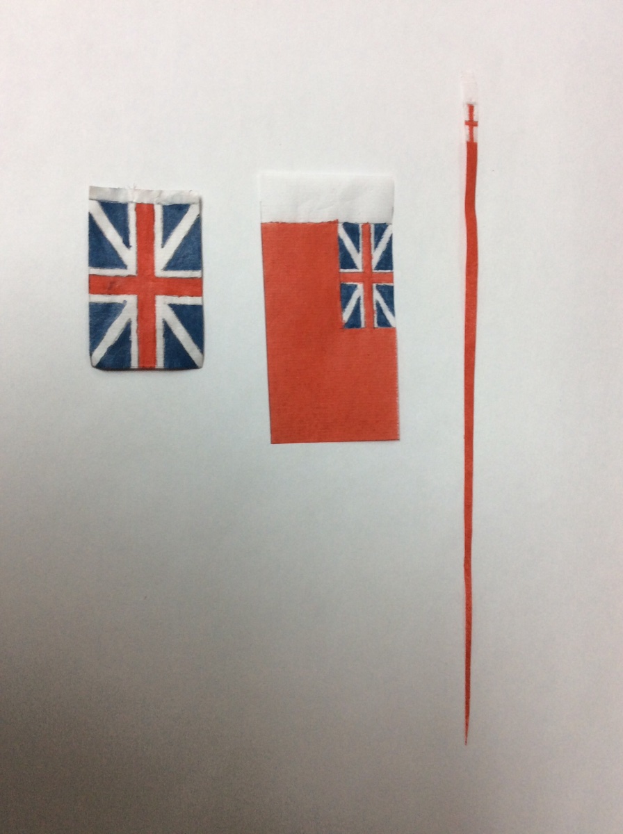
Stiff paper flags can ruin the appearance of a well built model and your beautiful model deserves lifelike ones.
Following techniques published years ago in the NRG I made flags that I an happy with for a Longboat model.
I used Japanese Rice paper. I suspect light weight Silkspan would work too.
I taped a xerox copy of the flag onto a hard surface; in my case, a homemade light table. I taped the rice paper over the xerox copy. With a sharp 4H pencil, I traced the flag on to the rice paper. I painted the flag onto the rice paper with thinned acrylic paints. I then turned the rice paper over and repeated the process, including pencil tracing of the flag. The pencil provides a little crease in the paper to help you paint a sharped edge. I did not paint white areas of the flag, instead I used the natural rice paper color. These flags can be teased into various natural shapes with a wet paint brush.
Keep in mind “scale distance.” In your case viewing the model from 1ft is equivalent to viewing the real thing from 48ft. At 48ft the stars in the flag would not show up with crisp 5 points, so you can cheat a little. I don’t know when sewing machines were invented or became common but I suspect that these flags were not machine made. Actual photos of old flags show that their geometry is not as exact as we might expect. Below is my attempt with shaky hands.
Roger

-
Glad to see this model found a good home!
In today’s Wall Street Journal there is a supplement dealing with retirement issues. The first page includes an article: Why Hobbies Are Crucial In Retirement. The article points out both Cognitive and Physical Health benefits gained through hobbies. Probably worth cutting out to show to wives complaining about “time spent in the shop, ship models cluttering up the house, money spent, etc.”
Roger
-
20 years ago, I decided to experiment with a simple 2D CAD system (Generic CAD) to see if I could a model of a Passaic Class Monitor. The body plan is included in a GPO booklet.
After drawing and printing a complete lines drawing , I cut out a section of hull for each body plan section and formed a stack- Jaager’s stack system. I then shaped the hull. Doing this was easier than the horizontal or vertical lift method. I simulated plating with paint; masking alternate strakes.
All went well well until late in the build tiny cracks began to appear between sections. Had the model been plated over the carved with some sort of material this would not have been a problem.
Moral of the story: This system works well, but make sure that you have sound glue joints between sections.
Roger
-
If you don’t have a shop and can’t or don’t want to set one up try to find some sort of shared shop space where you live. Adult education comes to mind. Go to your local lumberyard and buy a nice 1” straight grained pine board (actual thickness 13/16”). With your CAD system lay out 13/16” longitudinal slices through the hull either vertical or longitudinal. Print these and glue each to your pine board. Bandsaw out each slice, and glue up a the stack. Using hand tools and templates cut from the body plan, carve the hull. This is exactly how professional model makers have built ship models for 100’s of years.
There are companies that machine carve custom gunstocks. I don’t know of any specific ones. You might try checking them out. In the old days their machines duplicated a pattern. Today ai would think that they use CNC. Even these will require some final shaping.
Roger
OOPs. Bob Cleek said it better than I did. I didn’t read his post before writing mine.
-


Stuart Engineering Lathe by Rik Thistle - FINISHED - late 1800s - 1:12 (est)
in Non-ship/categorised builds
Posted
Instead of calling it machining, maybe they should change the name to “holding.” 90% of the effort seems to be set up and holding things rigidly.
Roger