


Roger Pellett
-
Posts
4,519 -
Joined
-
Last visited
Content Type
Profiles
Forums
Gallery
Events
Posts posted by Roger Pellett
-
-
-
I believe that you are over thinking this. If you have a set of mould loft offsets or the actual lines drawing, either of these will yield the moulded hull. In other words, the shape of the hull without its plating. The hull of the Missouri that you mention has been built to these dimensions.
The plating is added to this moulded shape. In the case of the Missouri model, the plating is so thin in relation to the size of the ship to be insignificant. If you want to add plating for realism pick a material and standard thickness. At a scale of 1:200, 80# plate is still only .01in thick and 17.5# about .002in. When you start worrying about the differences of .001in you’re in the realm of a coat of paint.
Roger
-
-
-
The different plating thicknesses and plating seams that you see on whatever drawing that you are using shows how steel ships were actually built. Different plating thicknesses reflect structural engineers using heavier thicknesses only where required by local hull stresses. This saved both weight and cost. If you are building a battleship, armor plating was added only in certain areas. The armor was so heavy that its extent was a major design factor. In any case the moulded line is the actual shape of the frame. The frame is not joggled ( shaped) to reflect different thicknesses of plating. The hull of a real steel hulled ship is therefore not smooth. There are steps in the hull reflecting different plate thicknesses.
Riveting of shell plating introduces more laps in the hull plating as the least expensive plating system was the “in and out method” where the joints in alternate plating strakes overlapped. Flush riveted construction requires heavy and expensive butt straps backing up all seams and except for some high end yachts was almost never used. In riveted construction the frames were still formed to moulded lines and Where the “outer” strakes crossed a frame, a backing plate was sandwiched between the frame and inboard side of the strake and rivets were driven through all three thicknesses. As late as the 1950’s even welded ships had some riveted joints.
The usual way to build a model with a plated hull is to build a smooth hull to moulded hull lines and to then plate the hull with material of your choice. If you look on the scratch build logs (1901 and later) my Benjamin Noble Lake Freighter model features a plated hull. For the plating, I used shellac saturated paper.
Roger
-
-
ABS rules require repairing a hole in a hull by first inserting a new plate extending at least 1ft from the old hole. While this makes sense for large diameter penetrations, applying this rule to old rivet holes made a riveted hull impractical if not impossible. ABS classification was necessary for insurance coverage.
Roger
- mtaylor, KeithAug and Keith Black
-
 3
3
-
I would contact Andy Davis at Tri Coastal Marine. I had a very slight contact with him when hiring a Naval Architect for work on SS Meteor Museum ship here in the Duluth Harbor. They were the Naval Architects and Marine Engineers for the Cangarda project. Still in business, I found them easily on the web.
The third paper describes the engineering plant though not in any detail. The interesting thing is that they are running a triple expansion engine and all of its steam driven auxiliaries with an unmanned engine room. They have overlayed 120 year old machinery with a computerized control system. The boiler is new. What I don’t understand is lubrication of the engine. He mentions using the old drip lubrication pots but old engines using these old lubrication systems required constant monitoring.
Roger
- Bob Cleek, mtaylor, Keith Black and 1 other
-
4
-
Keith,
Should you decide to build a model of Cangarda, SNAME and the Herreshoff Museum have published three collections of papers given at three Classic Yacht Symposium in the early 2000’s. Each of these includes a technical paper about the restoration of Cangarda. Much of the information is repetitive between the papers, but never less they are interesting. Some drawings made by Tri Coastal Marine, the project’s Naval Architect are included but unfortunately no lines. The hull was completely rebuilt; ABS the classification society would not agree to repair of the original riveted structure. Hull lines, therefore, must exist.
I don’t have time to do it right now but I can provide you with scanned copies of the papers.
Roger
- KeithAug, Keith Black and mtaylor
-
3
-
This may no longer be relevant, BUT: There are, or at used to be, certain projections; orthographic, isometric, etc. that are part of the language for communications between the engineering office and the shop floor.
In the industry that I worked in isometric drawings for piping systems were supplied to the field forces to aid in construction. These were made by our draftsmen from the various orthographic drawings provided by the project’s engineering company. The first CAD designers that we hired announced that they could make “better” pictorial drawings using different projections. They could not understand that isometrics were a product that we were selling to meet a contract requirement.
My son, also an engineer, took mechanical drawing in high school as an elective. This at least allowed him to learn certain fundamental industry conventions that are useful in his work.
Roger
-
Put it in the bathtub and see what happens! 😊
- rudybob, mtaylor, thibaultron and 1 other
-
4
-
-
What size deadeyes do you need? I’ve got lots of store bought ones in my stash.
Roger
- mtaylor and Keith Black
-
1
-
 1
1
-
-
-
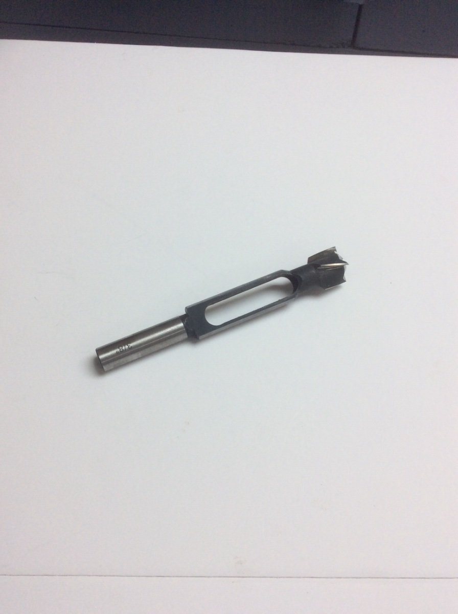
The last time that I made my own deadeyes I bought a Plug Cutter and chucked it in my drill press. I used this to cut 3/8in dia blanks. This method orients the grain correctly; across the diameter of the blank, instead of along the axis of the cylinder. I used a block of pear wood. The particular plug cutter that I found was able to cut a cylinder about 1-1/2 in long.
I then chucked the blank in my lathe and turned individual deadeye blanks to the correct diameter and shape. You should be able to find examples of homemade fixtures for drilling holes on the Forum. Ed Tosti’s Young America posts come to mind.
Photo of plug cutter:

-
If you want to say that it’s a scratch built model with everything built by you then it’s worth it.
- Baker, mtaylor, Keith Black and 1 other
-
4
-
Square stock for making shaft keys, (Keystock) is available from industrial supply stores and even some better hardware stores. I don’t know the exact chemical analysis of this material but suspect that it is ordinary non hardenable low carbon steel. This would work for turning tools intended for short term service and would probably last longer than brass.
I personally find an ordinary bench grinder difficult to use as the circular grinding wheel makes it hard to form straight shapes. I have one of those stationary belt sanders with a 30in circumference x 1in wide belt. I tried using this to form a lathe tool and it worked fine. It also worked better at controlling the temperature of the tool blank during grinding than the bench grinder.
Roger
- Bob Cleek, thibaultron, bruce d and 1 other
-
4
-
-
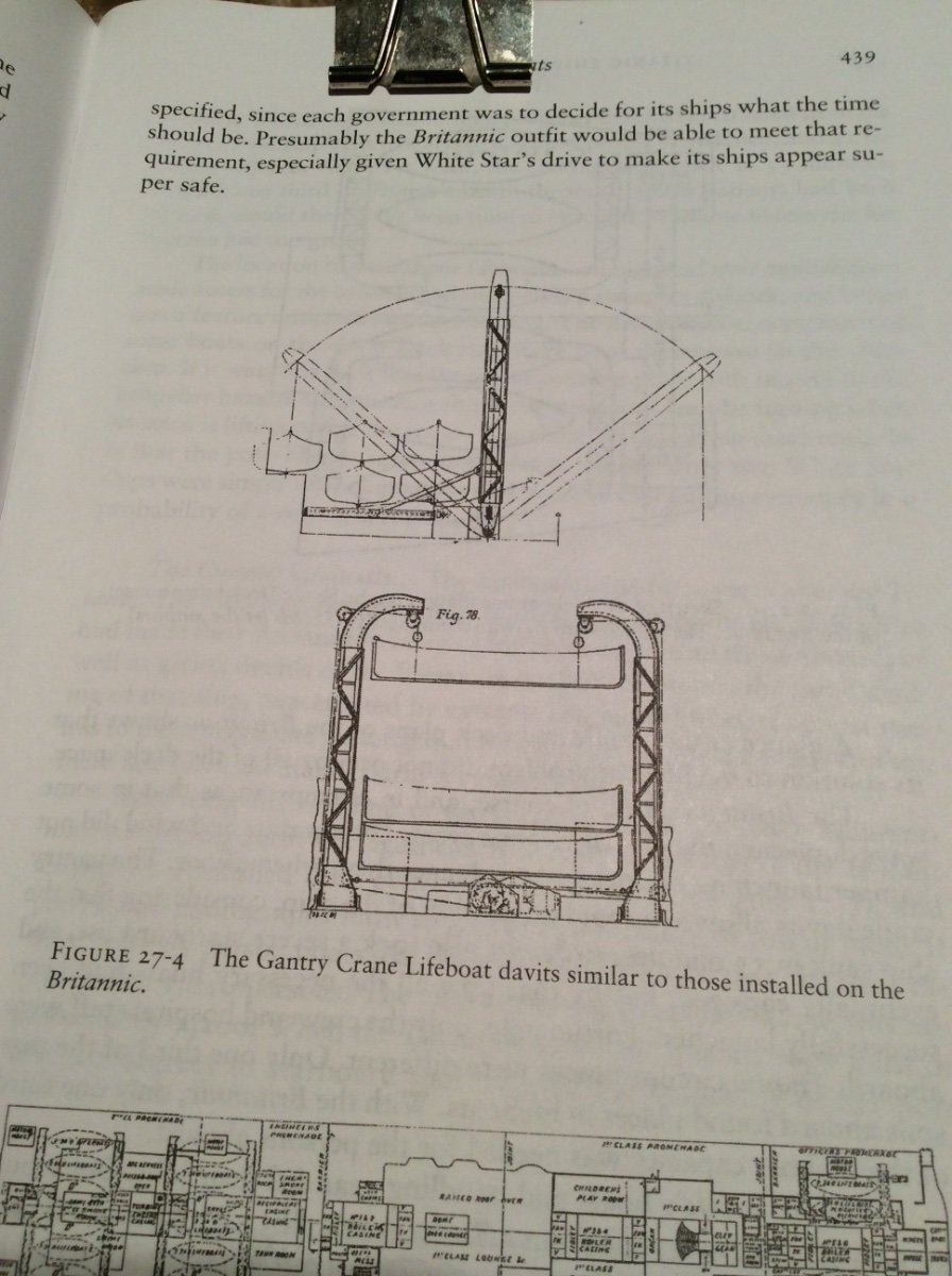
I believe that a major loss of life occurred when a full life boat got tangled up with the ships propellers. This of course happened after it had been launched. The lifeboat launching system worked as intended.
Roger
- mtaylor, Old Collingwood, Canute and 1 other
-
4
-
-
Kevin,
It could be one of any number of engine room vents.
Roger
- Old Collingwood and Canute
-
2
-
Kevin,
First of all, your model is beautiful and your doing a great job turning Titanic into Britannic.
I have one quibble! Like Titanic, I assume that Britannic’s fourth stack was a dummy. If so, would the dummy stack still have the relief valve piping running up its forward side?
Roger
-
Better to produce a model of a Baltimore Clipper that actually sailed in the early 1800’s than the Pride of Baltimore. The current Pride of Baltimore differs considerably from the original vessels as the underwater hull lines were modified to increase transverse stability following the loss of the original Pride.
Roger
- catopower, chris watton, Canute and 3 others
-
6

Ship paintings
in Nautical/Naval History
Posted
Pheasants are not supposed to be native to the Midwest USA. Supposedly they were imported from China. I thought those in Britain might be non-native too. That’s why I asked the question.
Roger