Roger Pellett
-
Posts
4,519 -
Joined
-
Last visited
Content Type
Profiles
Forums
Gallery
Events
Everything posted by Roger Pellett
-
If you are looking things up, another name for stealers amidships as Wefalck describes are “dropped strakes.” In this case the stealer amidships is considered to be the strake but is terminated as it approaches the end of the hull with shorter girth hence a “dropped strake.” Roger
-
"Sand Pebbles" motor Sampan from 1966 movie
Roger Pellett replied to JRB's topic in Nautical/Naval History
First of all the Sand Pebbles is one of my two or three all time favorite movies. The book which I have read several times is great too. Although, Steve McQueen did a superb job of playing the part of Jake Homan, his celebrity and classification of the movie as Action Adventure tends to hide the fact that Richard McKenna intended the book as a serious piece of literature. To try to help answer your question. On page 422 of Norman Friedman’s book Small Combatants there is a line drawing by A.D. Baker III of the Yangtze gunboat Mindanao. There are two motor sampans shown. The port rigged as an officer’s gig and the starboard as a utility boat. By blowing up the picture with a xerox machine you can get a top view and profile of these boats. Unlike the Sand Pebble movie boat these appear to be flat bottomed. The book is expensive so try an inter library loan. The forum moderators are touchy about posting copyrighted material, but if you send me a PM I’ll see what I can do. BTY Valiant Miniatures makes a great 54mm (1:32) cast metal kit of a Steve McQueen type figure with a BAR. Roger -
Johann, My apologies if you have already covered this elsewhere in your posts but do you make your own brass castings? Roger
-
An interesting topic. I have nothing to add directly to the question but I have wondered where these gunports were located close to the rail, how were they operated. How were the lids opened and what held them open. Where there was hull structure above the gunports, a rope pendent would have a sufficient angle to raise the lid. This would not be the case with ports just below the rail. Roger
-
Try successfully finer grits of polishing compounds applied to a motor driven rag wheel. If you’re not familiar with them they come in sticks that are held against the spinning wheel to load it up. You will need a new wheel each time that you change grits. Your shop must be free of any carbon steel filings shavings etc. that can contaminate the wheel or the part that you’re polishing. These will leave rust booms on your polished surface. Stainless steel isn’t really stainless. A cleaned surface will form a microscopically thin corrosion film that prevents further corrosion. This corrosion film is what gives it its characteristic grey color. Once polished, you would have to provide some sort of coating to prevent this film from forming There is also a process called electropolishing that is sort of the reverse of electroplating. That’s all that I remember from my stainless steel pipe fabrication days. You’ll have to look up the process. Roger
-
Re: Post #31, Above At least during the 1960’s the US Navy accepted officers who were not Naval Academy graduates for flight training. I was a 1965 graduate of the University of Michigan’s NROTC program. Like other NROTC units it produced both Reserve (like me) and Regular Officers. Candidates for a Regular Commission were required to make three 8 week summer Cruises. The first and third were at sea but the second was split between four weeks with the Marines and four weeks of flight training at Pensacola. Reserve officer candidates made one cruise, at sea. In 1962 between semesters in the middle of a Michigan Winter we were offered a trip to Florida for Aviation Orientation. Preference was given to Reserve Officer Candidates who would not have the four week summer flight training. They bussed us to Grosse Ile Naval Air Station and loaded us aboard an R4D, a prop driven transport that had a tail support that had to be attached when on the ground. The climax of the week was a flight with an instructor in a basic trainer. As much as anything I think that this was a chance for these guys to have some fun. First, they fed us a big lunch while warning us to be careful of what we ate. Then they took us up and did all sorts of acrobatics until we got sick. Upon graduation all of us, Regular and Reserve had the opportunity to apply for flight training. Fortunately for the US Navy and national security, I instead was accepted into the navy’s Nuclear Power Program where I couldn’t hurt anybody. And then of course there is the movie An Officer and a Gentlemen about a program to train aviators who did not graduate from either the Academy or NROTC. Roger
-
Mast base and sail cloth for a J-Class Yacht?
Roger Pellett replied to Markus16's topic in Masting, rigging and sails
Yes, Bar shrouds were another term for solid rigid rods instead of stranded wire rope. The America’s Cup has always been and continues to be a test of the latest technology. -
Painted Military Figures by Roger Pellett
Roger Pellett replied to Roger Pellett's topic in Completed non-ship models
Thanks, Keith, I spray them with Dulcote. In addition to protecting them it sees to give the finish depth. The difference is quite noticeable. Roger- 13 replies
-
- 11
-

-

-
Mast base and sail cloth for a J-Class Yacht?
Roger Pellett replied to Markus16's topic in Masting, rigging and sails
Markus, The recently published biography of W. Starling Burgess, Rainbow’s designer includes a full page description of her mast. (No Ordinary Being by Llewelyn Howland III, David R. Godine, Publisher, 2015) For her 1934 America’s Cup defense, Rainbow was equipped with an Aluminum mast with a “pear shaped” cross section. The cross sectional dimensions were 30in fore and aft and 18in athwartships. The mast was supported with bar shrouds. So, not only is the kit mast step inaccurate but the round mast that would fit into it would be incorrect too. Roger -
Painted Military Figures by Roger Pellett
Roger Pellett replied to Roger Pellett's topic in Completed non-ship models
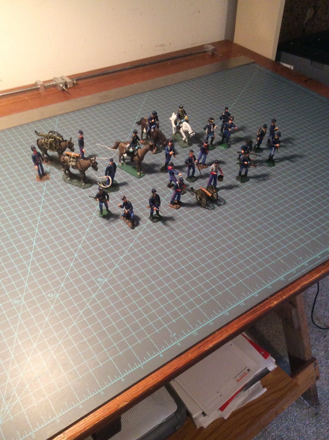
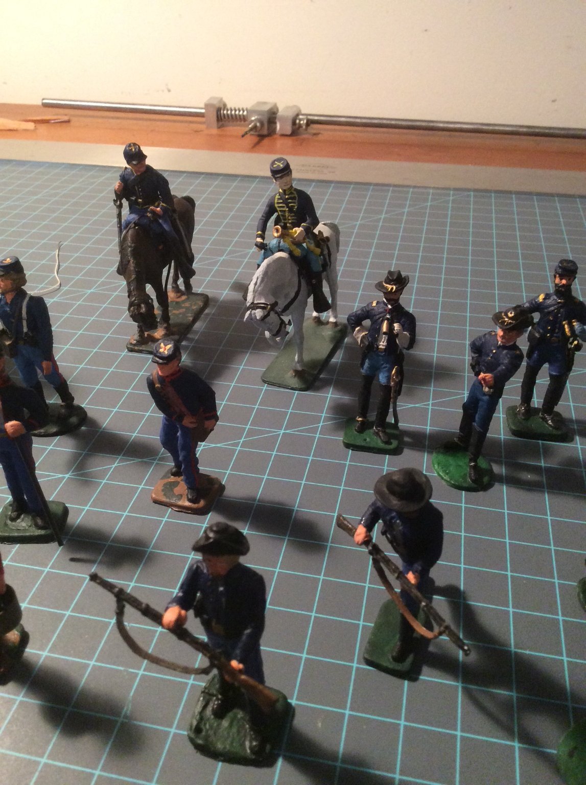
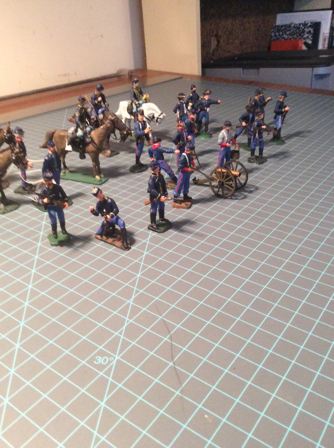
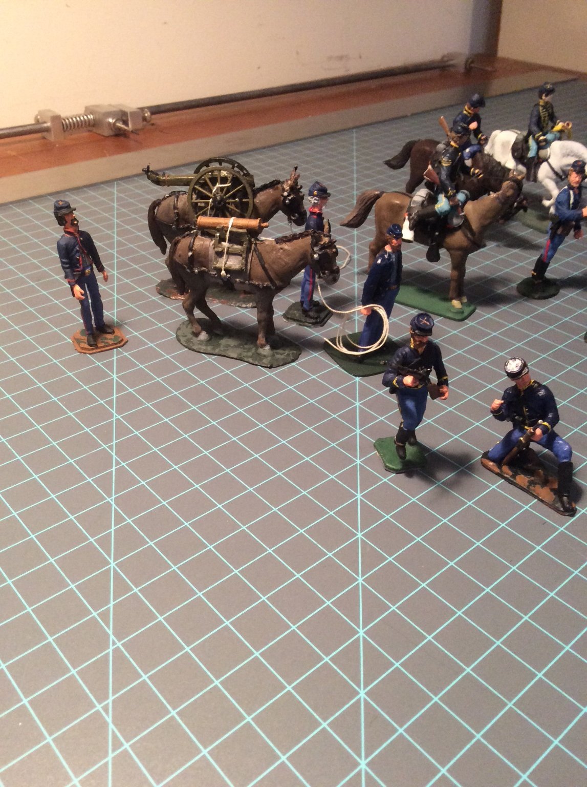
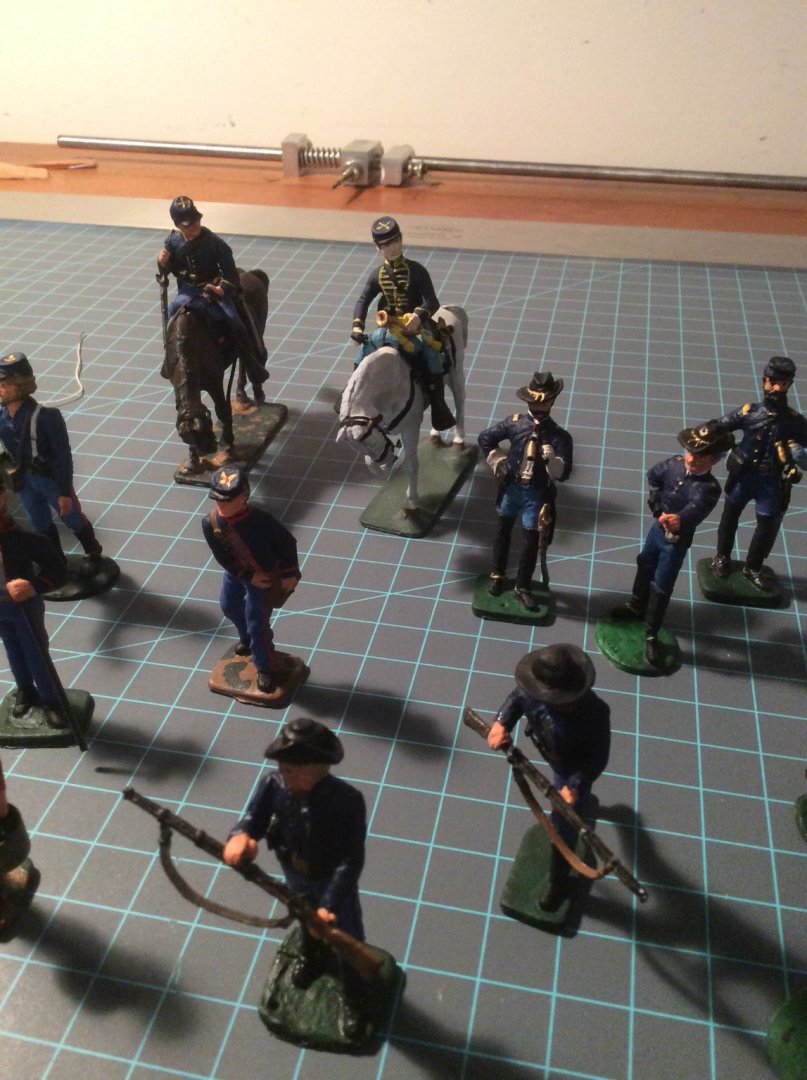
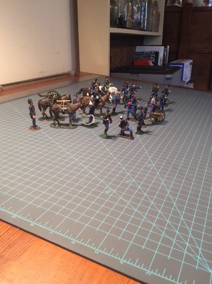
My latest military figure painting project; American Civil War, Western Theatre, Union side. A section (two guns) of mountain howitzers supported by cavalry and mounted infantry. My preferred figures were produced by Imrie Risley of Balston Spa, New York, now sadly out of business. They can be found on EBay but seem to become less available over the past 12 months. The howitzers and mules were produced by someone else.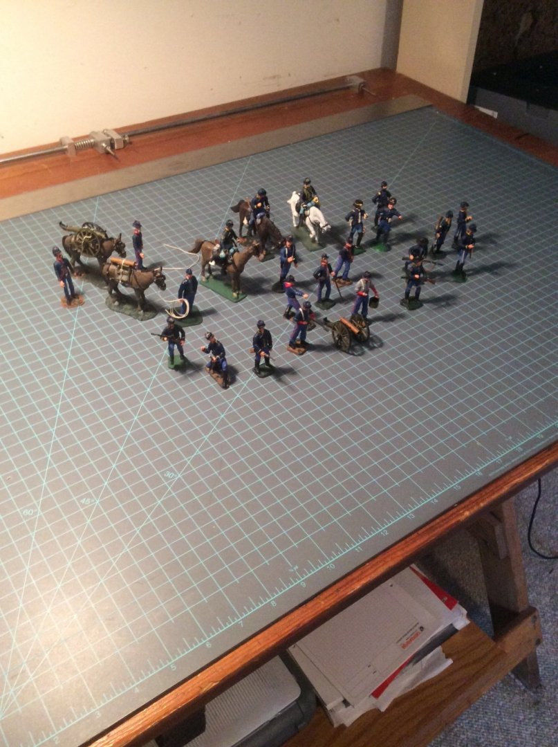


- 13 replies
-
- 13
-
-
As a kid growing up in the 1950’s in a suburb of Akron, Ohio I remember flights of these flying overhead. Goodyear Aircraft built them in a plant at the Akron Municipal Airport. This would have been during the Korean War. Roger
-
Mast base and sail cloth for a J-Class Yacht?
Roger Pellett replied to Markus16's topic in Masting, rigging and sails
In the 1930’s the working sails would have been made from heavy weight cotton duck canvas. Light air reaching jobs and spinnakers were made from Balloon Cloth a light weight tightly woven cotton cloth. I agree with Allan that trying to find a cloth that works for sails at any reasonable model scale is impossible. Silkspan is your best bet. On the other hand, in my opinion, models of these large sloop rigged J Boats look great without sails. Roger -
Rigging the 18th Century Armed Longboat 1/24 Scale
Roger Pellett replied to SeaDoc's topic in Masting, rigging and sails
You have two choices, make the hole larger or the thread smaller.😁 Seriously, first have you waxed the end of the thread before threading it through the hole? Also, before tackling a rigging job I like to arm myself with a bottle of clear lacquer type nail polish. Buy a cheap bottle with the brush in the lid. A small dab on the end of your rigging line stiffens it. While drying, roll the line between your thumb and fore finger to point the end. I personally don’t believe that kit manufacturers spend time sizing the line that they provide with their kits. I would not hesitate to find some thinner line if you need to. Roger -
Re Blackening: All metal work on Arnold’s vessel’s was forged at Skenesboro by blacksmiths working on site. A rough rusty look is appropriate. No was taking time to nicely finish or paint. Roger
- 36 replies
-
- 1
-
-
- Model Shipways
- Philadelphia
- (and 1 more)
-
Nice work! The engine cylinder would be insulated both for thermal efficiency and personnel protection. Wood strips, like those for your boiler were commonly used. Later, cylinders were jacketed with brass, the jacket containing a low pressure steam blanket. The exhaust line from the engine cylinder to the condenser would be considerably larger in diameter than the HP steam inlet line from the boiler to the engine. All steam piping would be insulated; white or very light grey color. Roger
- 26 replies
-
- 1
-
-
- Model Shipways
- Picket Boat
- (and 1 more)
-
My Sherline lathe recently died. Before spending $$, I decided to replace the switch as I found one in my electrical parts drawer that looked like had the right amp rating. The electronic speed control was wired to the switch with wire nut connectors. After struggling to get a good connection, something that should have been an easy job, I dug out my Soldering iron. Soldered joints covered with heat shrink tubing made a much more secure and neater job of things. Why Sherline used wire nuts on what is supposed to be a high quality tool Is beyond me. The new switch corrected the problem. Roger
- 433 replies
-
- 6
-
-
- open boat
- small boat
- (and 1 more)
-
I have had very good experience with onlinemetals.com
-
Great story Johnny! Tall tales are as American as apple pie and many involve transportation on rivers, lakes, and canals, although maybe this one is true?😆 Roger
-
Siggi, You are master of understatement! Drawing those friezes at any scale would be impossible for me, and I suspect others. Those flowing lines are beautiful and reflect skill, determination, and talent. Well done! Roger
-
Micro drill bit sizes
Roger Pellett replied to Peanut6's topic in Modeling tools and Workshop Equipment
Since your daughter not you is buying this, I’d advise you to keep it simple. Tell her to go to MicroMark and buy the round drill stand with drill bits 80 through 60 included. She may not be getting a great deal but the bits will be usable for 90% of the model building that we do. Small drill bits like these are somewhat disposable. They break easily and must be replaced. The drill stand is needed to keep them organized. I agree that you will need a set of pin vices. They usually come in sets of three to accommodate a range of drill sizes. There are also available from MicroMark. Roger -
Michael, More on the way down the road! C. V. Waine’s books are classics. His organization has also published a book by P.N. Thomas titled British Ocean Tramps. Also worthwhile. Roger
-
Ships launched on slipways were NOT constructed with the keel blocks on a level plane. The declivity had to be sufficient to allow gravity to do its job. Eric Ronnberg, a highly regarded model builder and historian of New England maritime history has written that declivity was 3%. When the ship was ready to be launched, the slipways were laid down and heavily greased with tallow. Cradles sitting on the slipways were erected bow and stern under the hull. On launch day 100’s of wedges were driven into a space in the cradles left for that purpose. These lifted the hull very slightly to allow the weight to be transferred from the keel blocks to the cradles. There was some sort of trigger mechanism built into the one of the cradles and when this was released, hopefully gravity would do its job. While it would be theoretically possible to build the vessel on level keel blocks and then launch it on an inclined slipway erected for the purpose, practically this would be impossible to do with the technology available. If the vessel had a keel length of 100ft, the bow would have to be raised by 3ft, the stern lowered by 3ft or a combination of the two. Roger
-
Resistance Soldering Unit
Roger Pellett replied to Roger Pellett's topic in Metal Work, Soldering and Metal Fittings
Thanks, i’ll See if I can find a copy. -
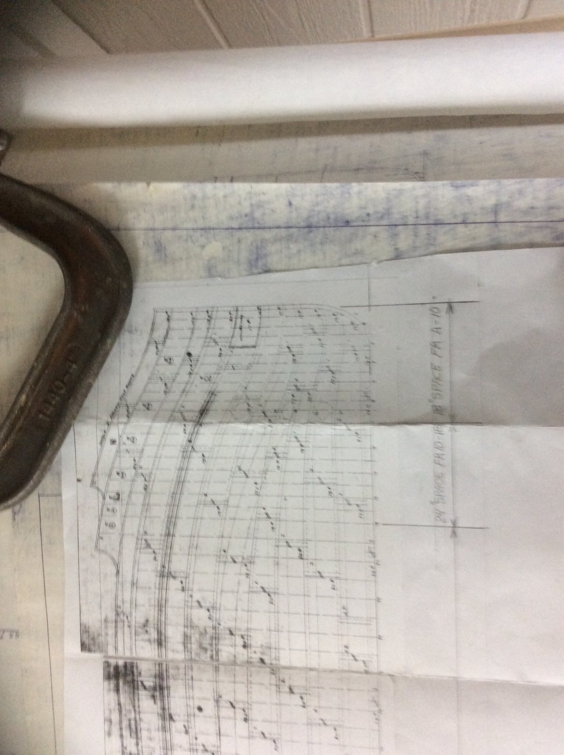
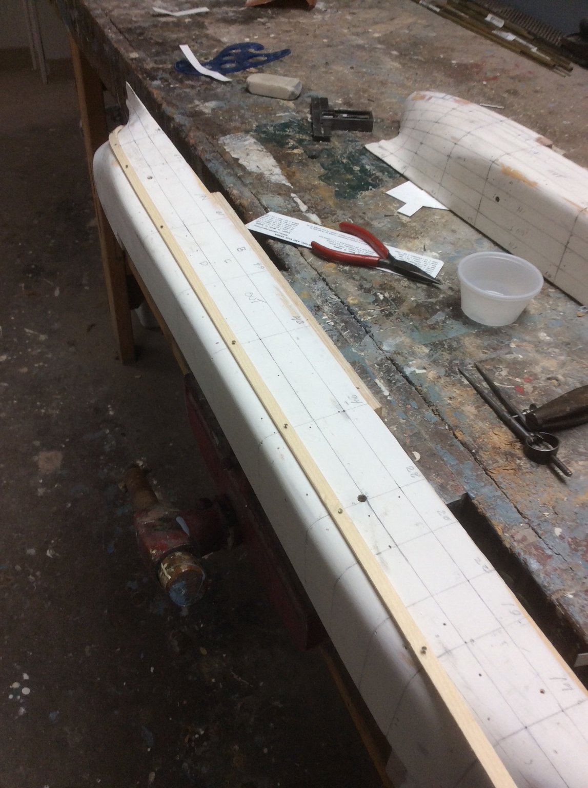
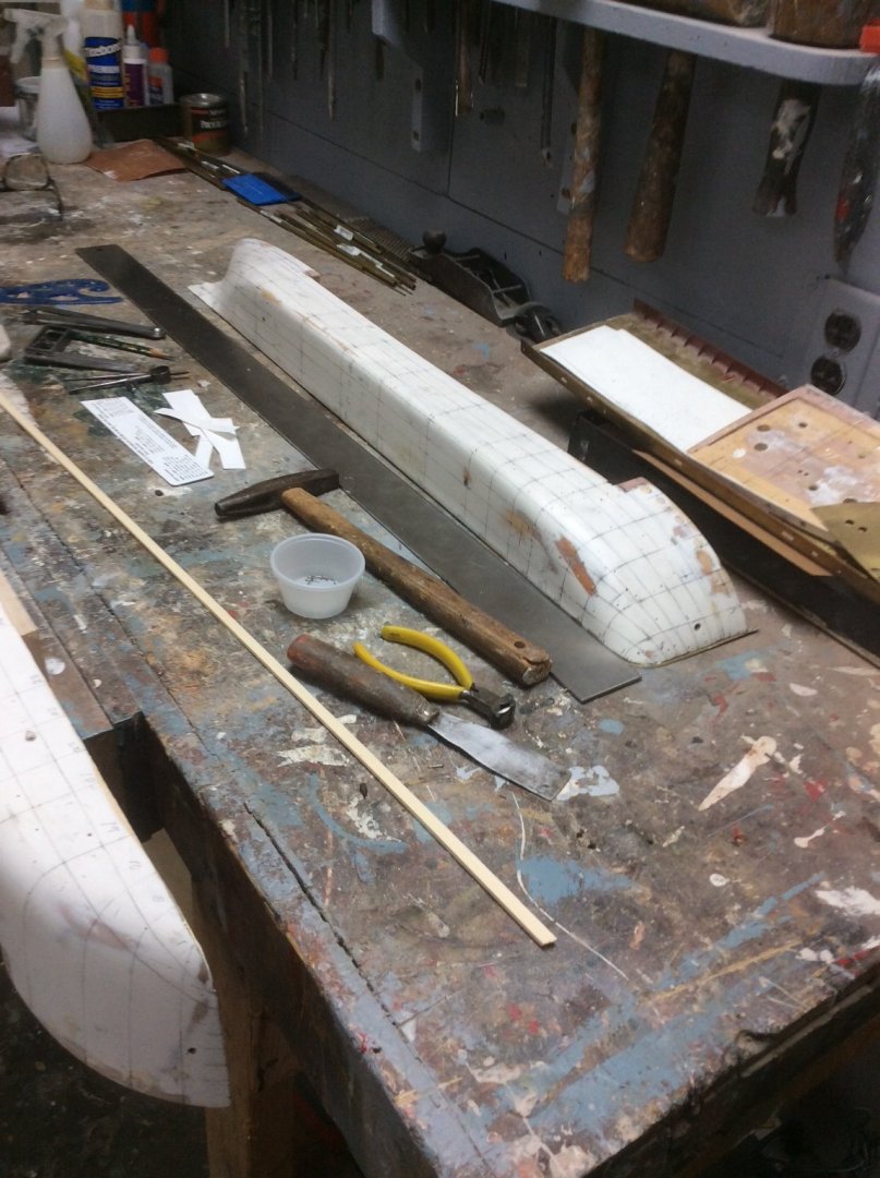
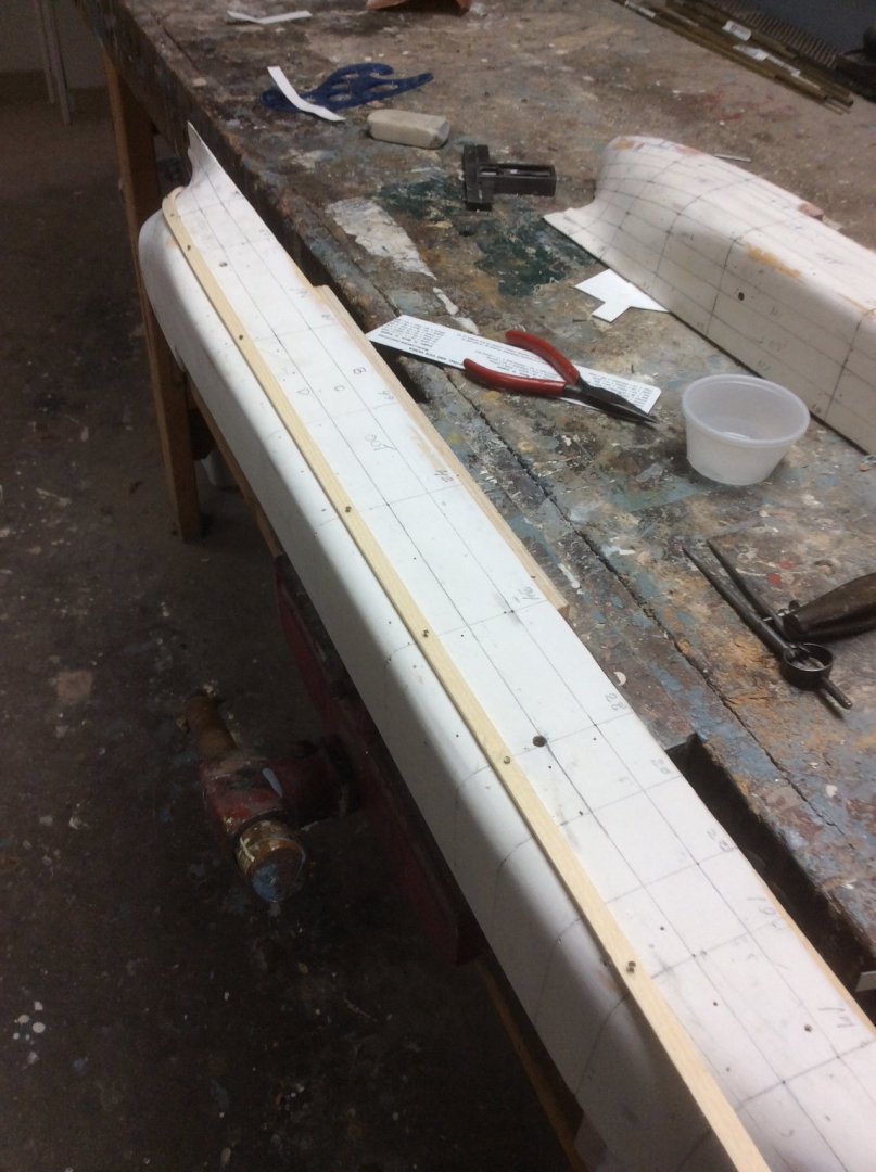
CHAPTER 5. Marking Out the Plating. Unfortunately, with their full lines and slab sided hulls, models of Great Lakes ships can look just like what they are: a block of wood. Before beginning this project many years ago, I decided that the model must include an accurate depiction of hull plating, both to add interest and accuracy. The need for this has interrupted progress on the model several times while I tried out and abandoned different ideas and plating materials. I now think, or rather hope, that I have found a solution and will cover this in a future chapter. Before beginning actual plating, however, the hull must be Marked Out. Marking Out was the ship design office’s name for arranging the individual hull plates on the plating model. That’s right, I said model. BC (Before CAD) a half model was carved and the individual plates inked to scale on the surface. A Takeoff of the plates could then be made and a bill of material created to allow the steel to be ordered. One contemporary author has written that the draftsman’s skill was judged by the amount of scrap created in building the ship compared to his bill of material. From the plating model a Plating Expansion Drawing was also created for use in the shipyard. The plating expansion drawing shows the true location of each frame and vertical plating joint on the X (horizontal) axis but the GIRTH of the hull at each frame location on the Y (vertical) axis. It, therefore, shows the same information as the plating model but in a two dimensional format. Here is my copy of the bow section of the original plating expansion drawing for. Benjamin Noble: The vertical stem is not distorted as it’s “girth” is equal to its vertical height but as we move aft it bulges upward as its girth increases. In marking out the hull for my model, I am going to reverse the process used by the ship’s designer. Rather than use the model to create a planking expansion drawing, I will use the drawing to mark the plates on the model. It is highly unlikely that my model will exactly match in all three dimensions that carved for the ship over 100 years ago. First, I used digital information, a table of offsets, to create a lines drawing then I used the lines drawing to carve a hull. Regardless of my skill or that of the original designers our results will differ however slightly. With this in mind the plating expansion drawing becomes a guide, not an exact design document. I started the process using a homemade arbor, an inverted U, to mark selected frame locations; more closely spaced at the ends than in the middle body. Here the two half models worked to my advantage as I could lay the centerline surface of the hull on a flat surface. I then used Tick Strips, narrow strips of paper to record the girth dimension of each strake of plating at each of my selected frame locations and these were transferred to the model. From my canoe restoration days I had saved several long strips of clear grained spruce. These were ripped into battens with a cross section of 1/8in x 1/4in From another project I had a drawer full of 3/8” very fine steel nails. The idea was to tack the battens along the hull at each frame location and mark out the strakes. My collection of tools for doing this is shown in the first photo. For the most part, my system worked well and I gained confidence as I proceeded. As you can see, the plating makes a sharp turn near the stern and I broke several battens. While some points didn’t line up, in general things followed the drawing. I was also pleased to see that a number of surfaces that appeared difficult to plate worked out quite nicely in 3D. It was not necessary to mark individual plates within a strake as almost all are a standard 24ft long, 3in to scale, so once the registration of each strake is determined one plate follows the next. Roger

-
George. Before the current system of modular construction, ships were built in two phases. Construction before launch, and Outfitting after launch. Construction was done by shipwrights. Outfitting was done by joiners. Building ladders, cabin partitions deck furniture etc. was the job of joiners. My guess is that you are correct. In doing their job, the joiners would build their structures level and square to the ship afloat. The disposition of frames is a different matter, as they determine the shape of the hull. If the frames were not arranged parallel to the body plan sections on the draught, the entire draught would have to be redrawn to shift the orientation of the body plan sections to match that of the frame orientation. Otherwise the shape of the hull would change.