

Chuck
-
Posts
9,079 -
Joined
-
Last visited
Content Type
Profiles
Forums
Gallery
Events
Posts posted by Chuck
-
-
That looks very good. You will always have various lips and small areas to be sanded like that.
Also a Tip…sand both sides of the sheet before you remove the parts in order to clean the laser char spots.
- yvesvidal, Freebird, Stuntflyer and 2 others
-
 5
5
-
I dont use a scientific method at the stem or the stern. For that I use either thin tape or string along all of the other tick marks and just extend them to the bow by “eye”. Its a bit of both art and math when lining off a hull. Adjust the tape or string by eye examining the hull a lot from various angles. When satisfied…mark the locations along the stem post and stern post with a pencil.
- allanyed, Ryland Craze, Baker and 3 others
-
6
-
Excellent work and great start. You have some nice tight joints there.
- Ryland Craze and CaptMorgan
-
2
-
-
beautiful work as always..
- mtaylor, Keith Black, FriedClams and 1 other
-
4
-
-
Manual…pin vice. Takes forever but its the only way I do it.
- KentM, Ryland Craze, sfotinos and 1 other
-
4
-
That looks very good. A really nice start.
- davec and Ryland Craze
-
2
-
The fcastle deck beams were glued into position . The knees, carlings and ledges for the hatches were added as per the usual. The knees are laser cut and just need some sanding to get a tight fit against the frames. The ledges and hatch framing is completed with 1/8 x 1/8 strips. Cut them to length and follow the framing plan.
To finish off the fcastle for now...the ladder was made for the companionway on the starboard side. You can just make that out in the photo. This is as far as I will take the fcastle which matches where I left off on the poop deck.
So this completes chapter six believe it or not. Chapter seven begins with the few cabins and sail room on the forward lower platform. More to come on that soon I hope. But I have to start laser cutting some more chapter sets and making more rope. Having a real job stinks....what I wouldn give to hit the numbers tonight, LOL.
Chuck
-
Maybe...but seriously we need more than two build logs. If we can get that number up to ten or so then yes certainly. But of those who bought the first dozen or so kits, if we see 3 build logs it will be a lot. Lots of solitary builders out there unfortunately.
Chuck
- KentM, dvm27, Ryland Craze and 3 others
-
6
-
41 minutes ago, Jim Rogers said:
Question Chuck, should I wait to install the short frames until after all the tall frames are installed or can I install as they come up in order?
Its up to you. I found it easier to add them as I go. As long as you have a frame on either side you can add the shorter frames. I also added the port fillers as I went but that is something you can wait to do until you have three or 4 ports to make. This way you can use the template to make sure they are all at the same height and spaced accordingly. But its up to you.
-
-
-
-
Indeed it does. That is looking very good. Hopefully we will have more build logs starting soon as well.
- Ryland Craze, CaptMorgan and Mr Whippy
-
3
-
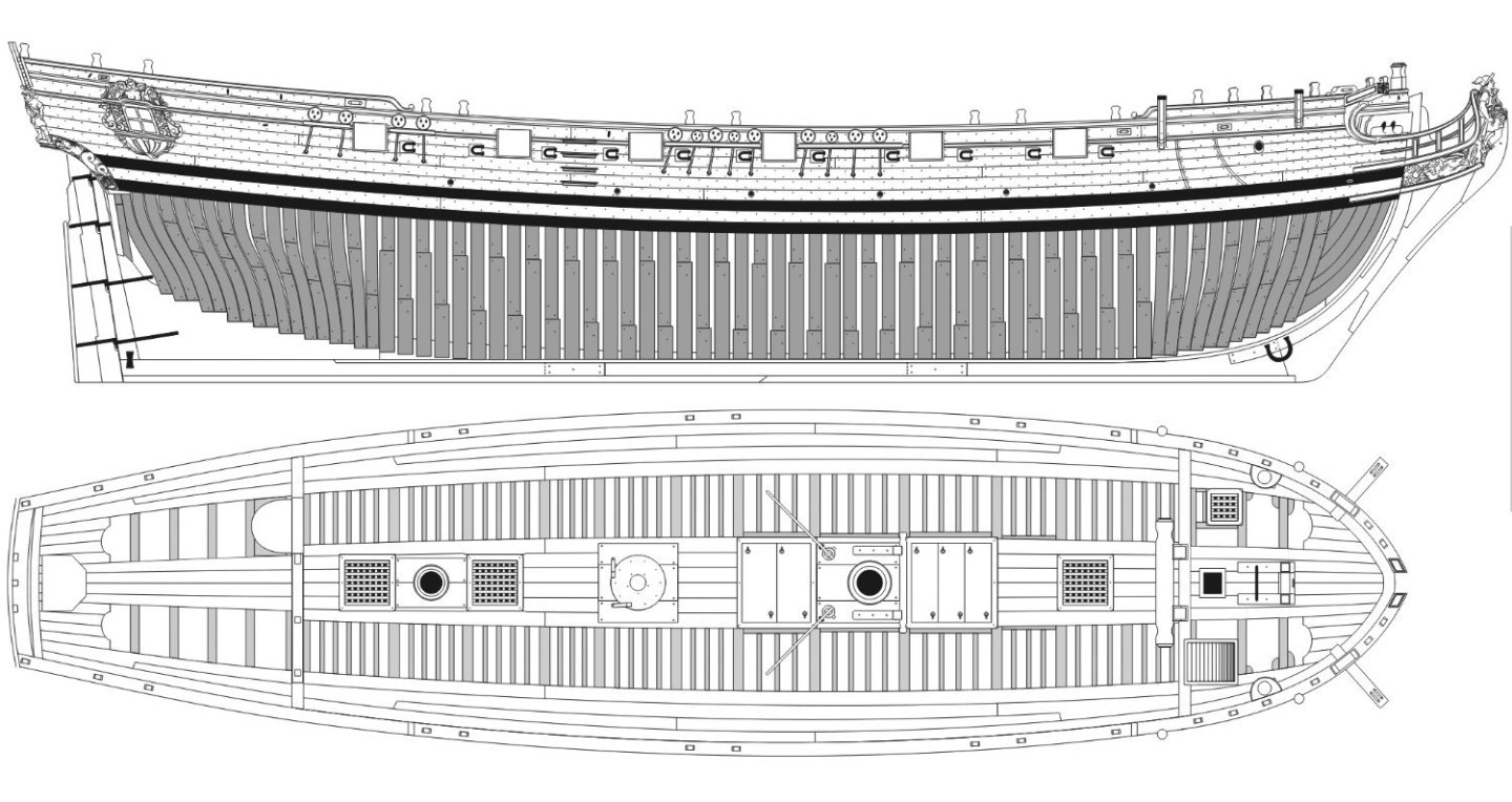
Lots of drafting to do....Deck Layouts almost completed.
-
-
Just a heads up...I have decided to make the plan sheets for this project available electronically. Many have asked for an additional set so they can cut them up or so they can have a clean extra set. Although I am printing them and including them with each appropriate laser cut installment, some folks may be worried about stretching and or shrinking of the folded paper plans provided as well. So to ensure there are no issues they are available electronically and can be printed on your own for a spare set to cut up as well. I routinely cut them up myself to use for templates and such. Since no framing parts are included there really isnt a concern that this will lead to copying of my kit design. Not all laser cut parts are shown on the plans...for good reason.
So here are the first three....plan sheets completed. The remaining will be added to my website once I am sure they are OK, after I build those areas of my prototype.
They are also available on my website
-
-
Just a heads up for those building the kit. Jim Rogers caught a error on the labeling of parts. It is now corrected. But you will find that there are two sets of frame parts AF.....The taller set is actually AF. The shorter set is mislabeled. Those are actually 10A. Good catch Jim....thank you. The parts are actually fine. The one set is just mislabeled. So grab your parts and correct the label on the shorter set before you get that far. Label them as parts 10a.
You will find them on sheet "M" of laser cut parts. Those need to be relabeled.
Chuck
- Rustyj, mtaylor, FrankWouts and 11 others
-
14
-
Work continues on the forecastle area. With those first two beams in position I can now start working on the bulkhead that sits against them.
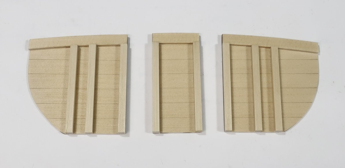
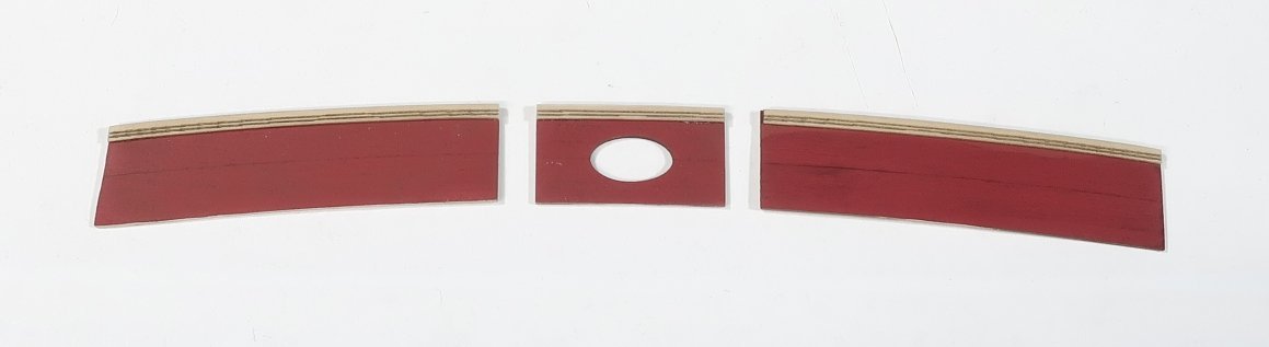
In this first picture, I am just test fitting the three sections of laser cut bulkhead. These (like all others) are laser cut slightly wider and taller than needed.
First...work on getting a nice fit on the center section between the riding bits. Only worry about the width on both sides...dont worry about the height of these yet. The two pieces on either side are next...sand the outboard side ONLY to reduce the width and get a tight fit against the riding bitts. There will be a space between the frames and the bulkhead where the inboard planking would have been. Try and make it a consistent width. Again dont worry about the height.
Only after you get the widths taken care of should you then sand the top of each bulkhead section down so the height is flush with the top of the lower beam. The photo shows the three sections with a proper fit all around...now its time to detail them.
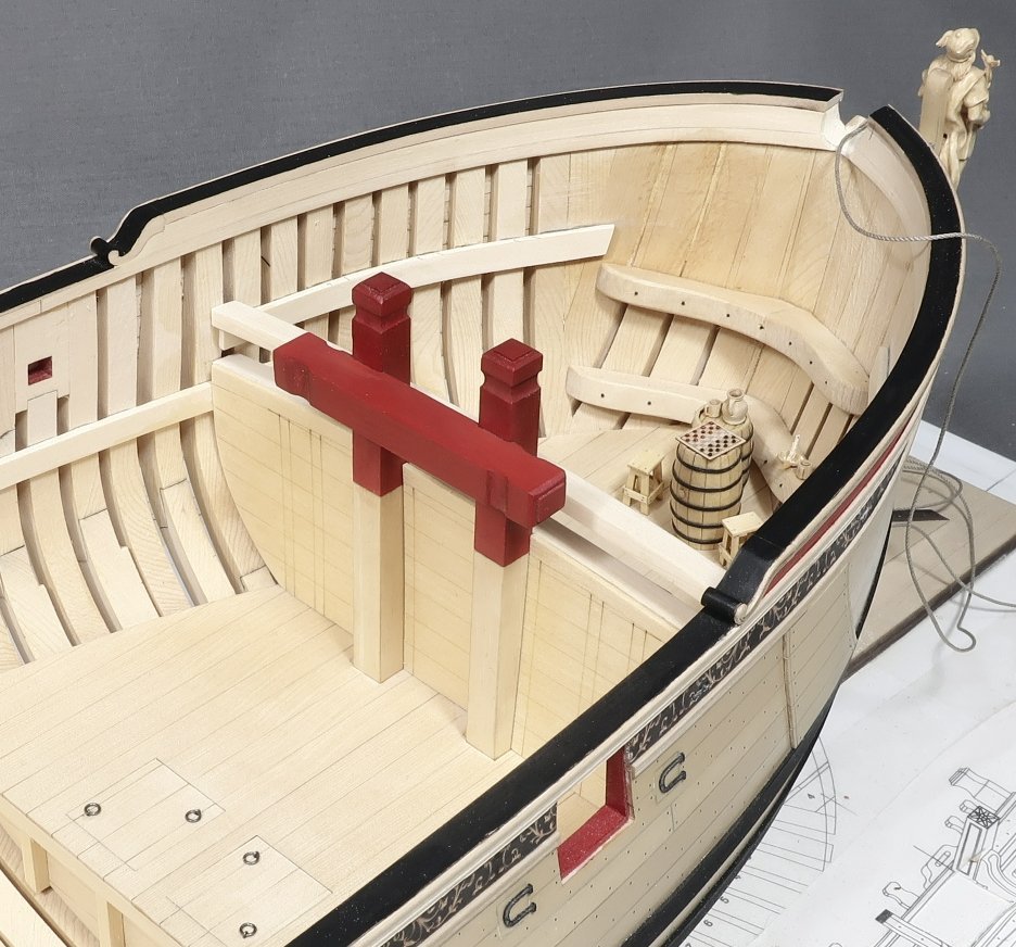
Remove the three sections so you can add the uprights and simulated deck beam. First up...sand the char from the laser cut beam pieces. These are glued to the top edge of each bulkhead flush. They are laser cut longer than needed so you can sand the sides flush as well.
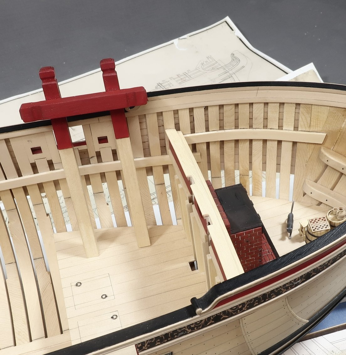
Then the uprights go in position. These are the uprights for the cabins on the lower platform. We will be adding them a little later. But it is easier to add these now. They are just 1/8" x 1/8" strips cut to length and glued in place. There are laser etched lines that show you exactly where they should go.
Then glue the three sections in position permanently on the model. Note the riding bitts will not be glued on permanently yet. They will just get in the way when we are doing so many other things in this chapter. So make sure you can remove it after the three sections are glued in place.
Riding bitts removed.
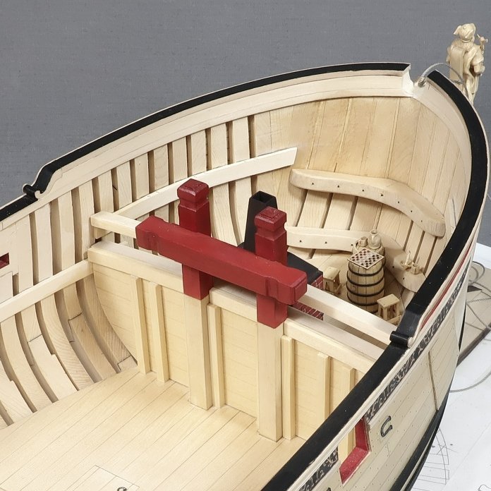
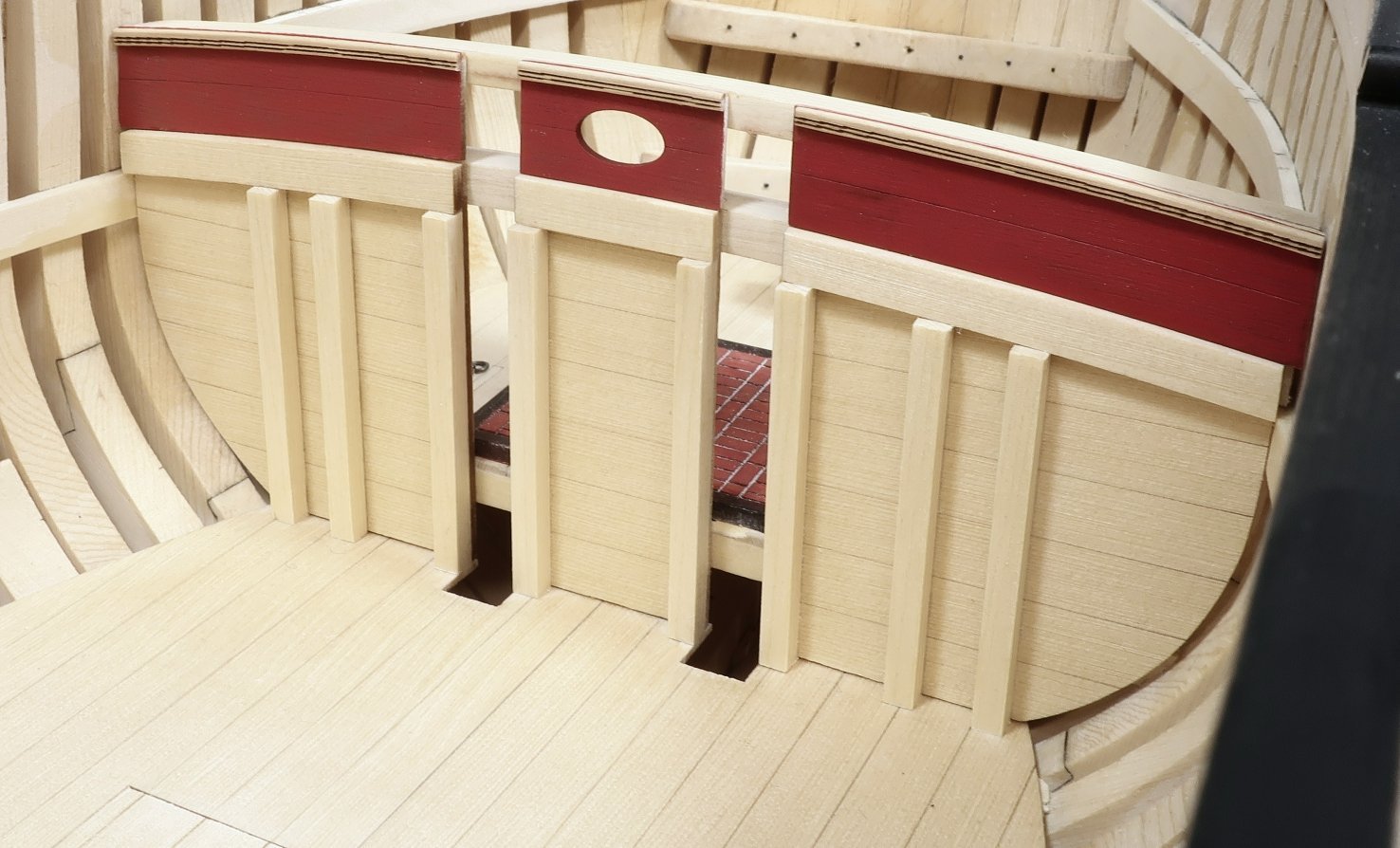
Now for the next layer above that. this is handled in the exact same way. I could have just included these on the first three section only a bit taller, but I wanted to be able to paint them cleanly and get a crisp edge. But the same principle applies here. Sand the widths of each first....then get the heights done. These are flush with the top of the fcastle deck beam. Then remove them.....
Paint them red. Then add the laser cut and etched molding along the top edge. The molding was rounded off on top and bottom. You could also scrape your own if you want to.
Then sit this on top of the lower sections of bulkhead as shown below. The riding bitts are still removable but you must use them to get a good fit. Glue these bulkhead sections in position now as well.
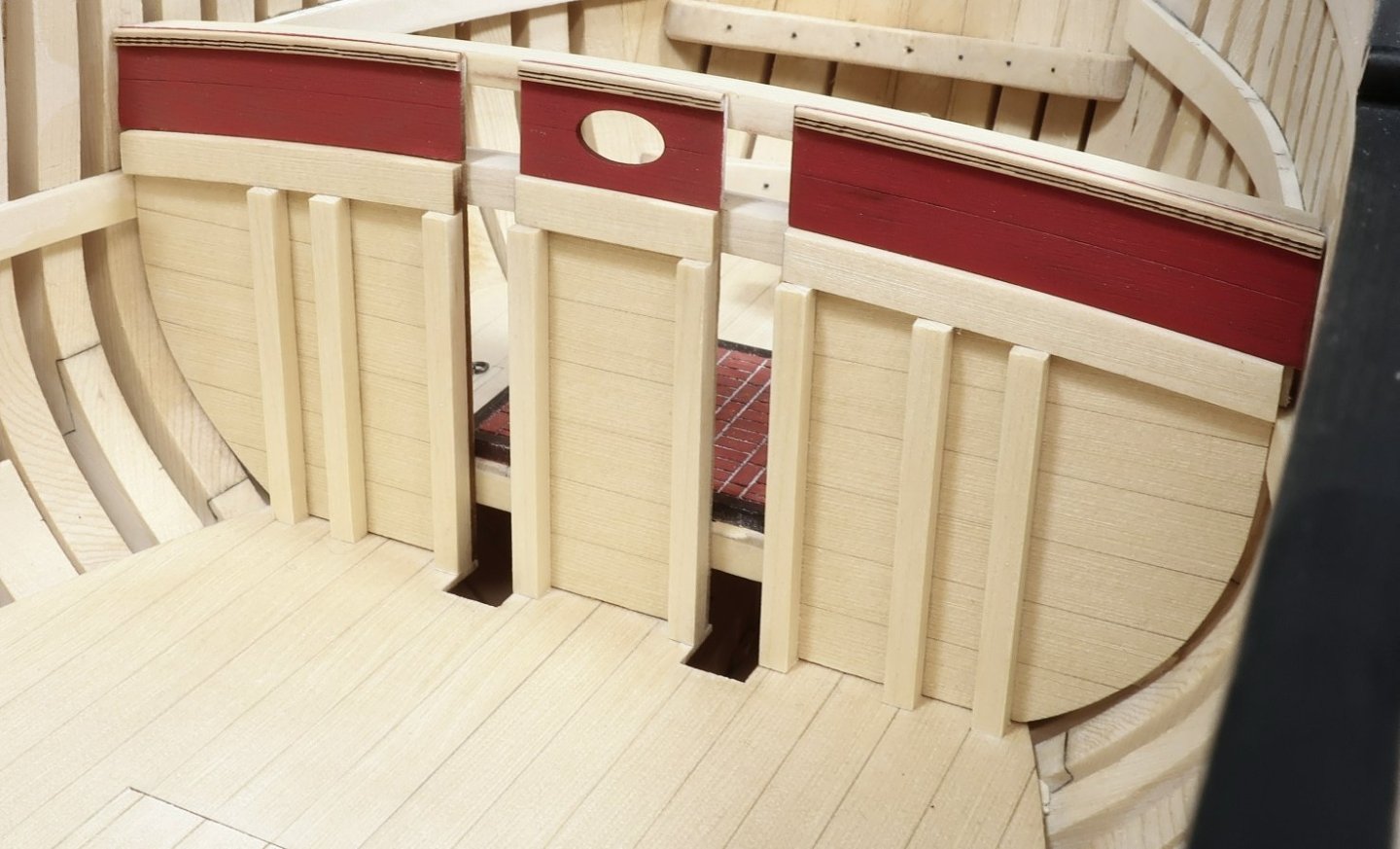
Top this off with the margin plank along the beam. Cut a 1/4" x 3/64" strip for this. Basically, just like you added for the quarter deck margin plank. It hangs over the bulkhead a little bit. The aft edge hanging over is rounded off a bit to your liking. The forward side will leave a nice ledge or rabbet for the fcastle deck planking.
The only difference here is that you must notch out this plank for the riding bitts.
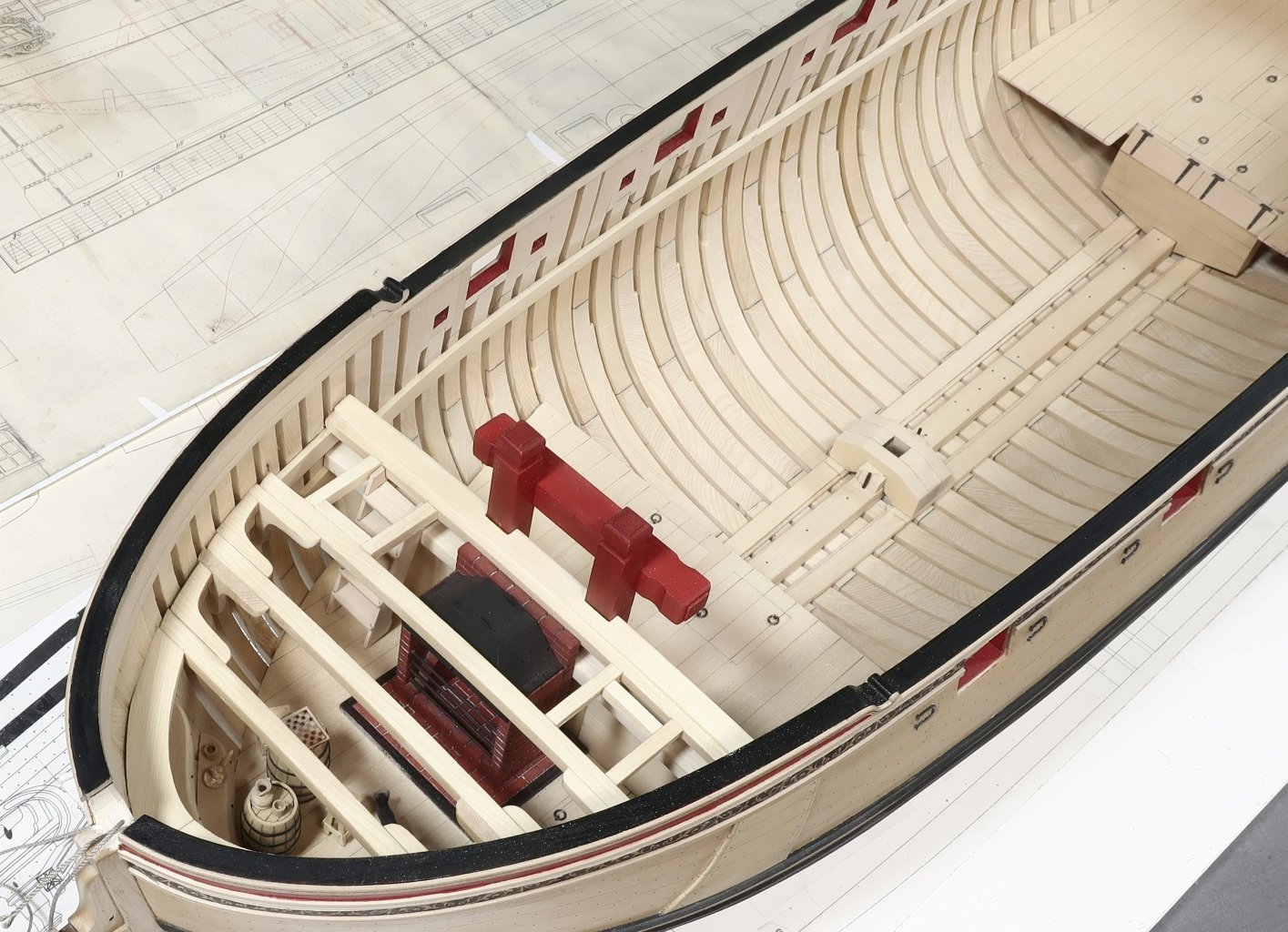
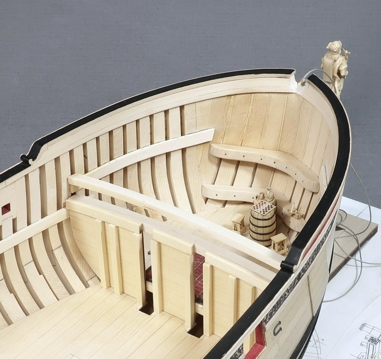
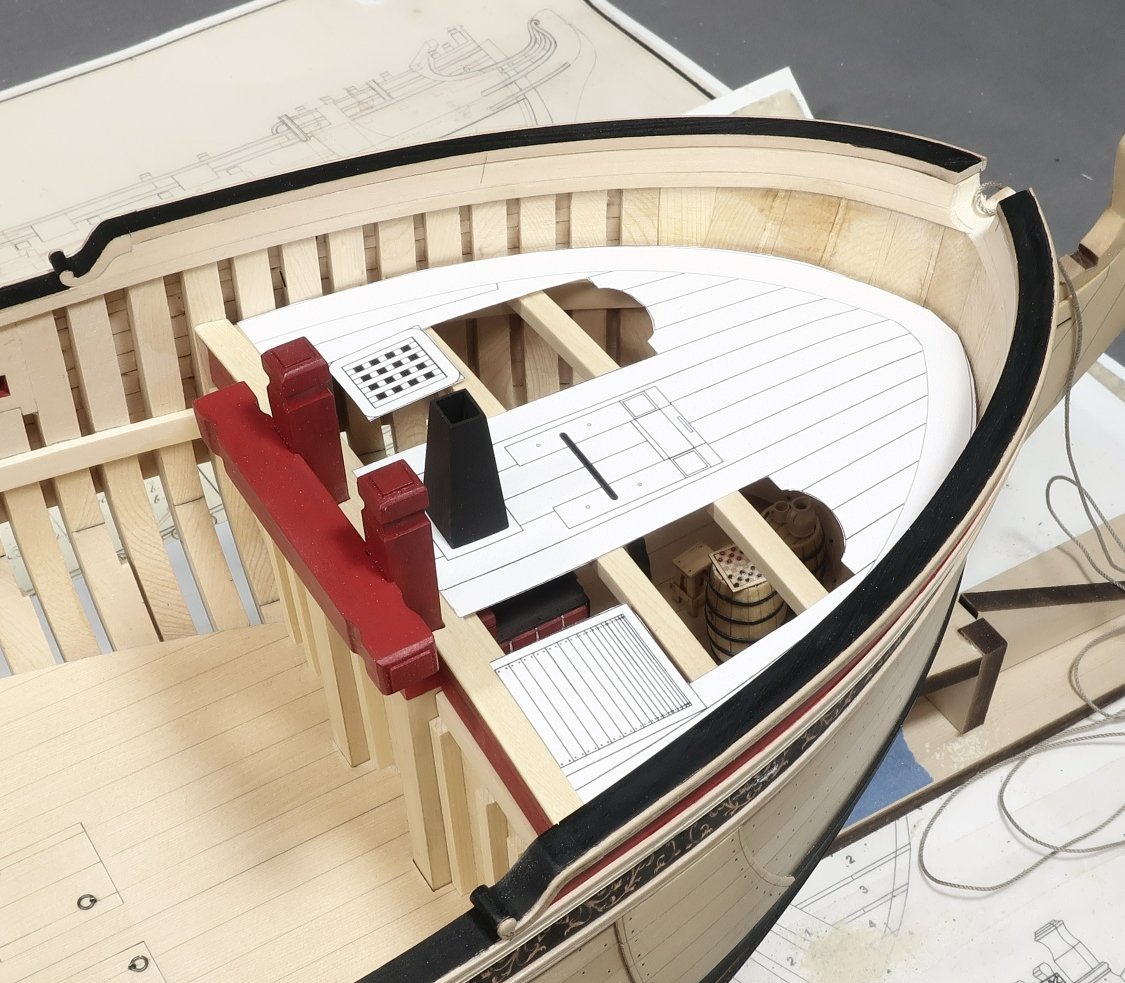
see below. Also the riding bitts are not yet glued in position...I will let you know when its best to glue that in position. BUT I did finally glue the fire hearth in place permanently. Just remember to do so without its stack. That will just break off later without a doubt. And if you want to add anything else to the galley...do it now. We are about to close her up for good with deck beams and knees, etc.

The three fcastle deck beams were cut to length and are just resting on the deck clamps. I must locate their exact positions using the plans.
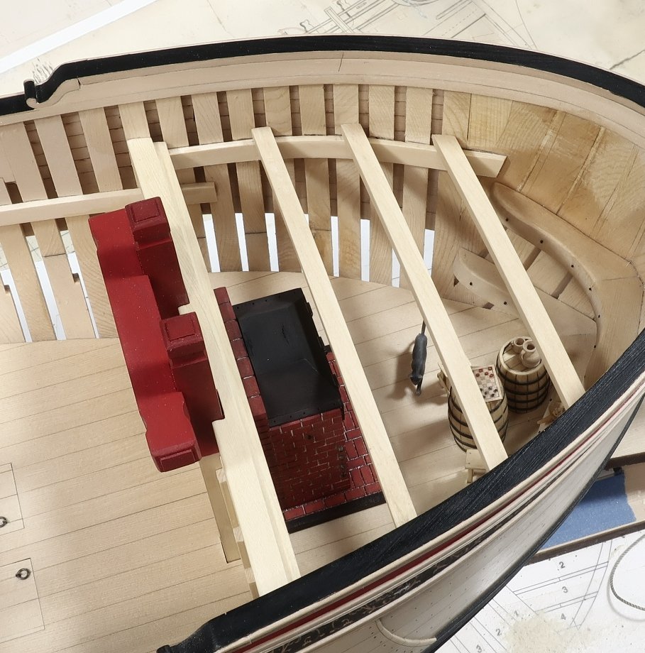
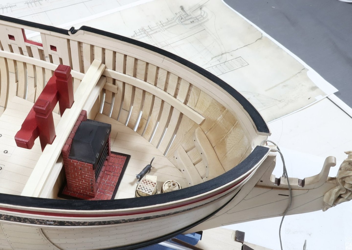
Thats it for now...BUT I did get a chance to cut the plan sheet up to see how my planking design will look. Its always tricky deciding how much planking to add or leave off the model. I think I am liking this particular cut-away with some planking removed. You can still see quite a bit of stuff down there...
The hearth stack was just placed on top for giggles and a test.
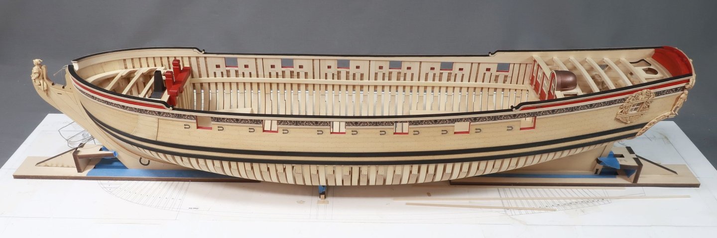
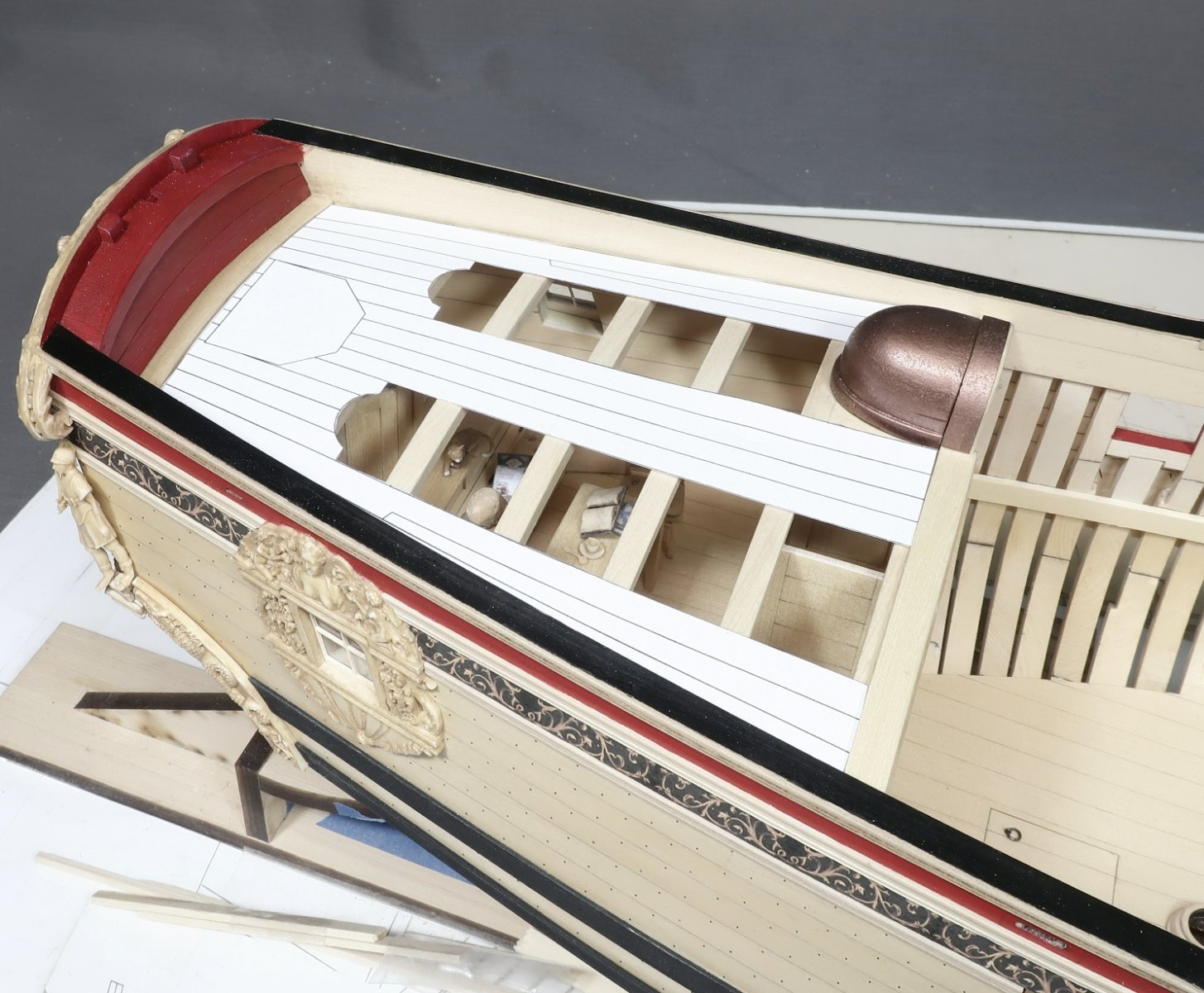
I also did the same for the quarter deck...once again plenty of detail is still viewable down there. I will live with these templates for a while and mull over some other possible planking schemes. But so far I think these will do just nicely. What do you think?

-
Glad to see a build log.
Yes…i actually have a photo of that. Which you posted. The circled areas (on one end or the other of a given joint) need to be sanded to close the gaps. The gaps are intentional and yes you will need to sand the end of the scarph on the opposite side to close the gaps. This will be especially true with each frame segment as the thick wood when laser cut leaves a curved and bevelled edge that wasnt easily remedied by just flipping the pieces on the laser cutter. So each piece will have one end that needs just a hair of sanding.
See the page of the 1st chapter that explains this.
Just a few swipes should do the trick.
Chuck
-
Looking really food Ken.
- FriedClams, mtaylor and KenW
-
3
-
While most folks here are concentrating on the software I would first find out the capabilities of that Library laser cutter. You will want to cut wood ….depending on species that can get pretty thick.
My guess is this laser cutter wont be of high enough power to cut anything more than 3/32” thick basswood. And certainly not ply unless its very thin. So check the specs before you start.
you would certainly need a 60 watt laser at a minimum but that is pushing it.
its far better to use 80 to 100 watt laser. Otherwise it wont cut the thicker stuff at all. Smaller machines for paper and light crafts are useless for ship model work.
- iMustBeCrazy, mtaylor, ferretmary1 and 1 other
-
4


Sloop Speedwell 1752 by Chuck - Ketch Rigged Sloop - POF - prototype build
in - Build logs for subjects built 1751 - 1800
Posted
More details inboard...sneak peak...