HOLIDAY DONATION DRIVE - SUPPORT MSW - DO YOUR PART TO KEEP THIS GREAT FORUM GOING! (Only 13 donations so far - C'mon guys!)
×


Chuck
-
Posts
9,660 -
Joined
-
Last visited
Content Type
Profiles
Forums
Gallery
Events
Everything posted by Chuck
-
 Looking forward to seeing this Ben...
 -
Absolutely beautiful work. You should be very pleased.
-
First print test. I have a few modifications to make and I dont have any clear resin…its on the way. This resin is just plain old elegoo resin which I use for my tests. Then I dipped into some wood stain. When I get my delivery of the good stuff it should make a huge difference as well. But this test proves the parts actually fit...I am pleased about that. Anyways…I will make some tweaks and print again.

-
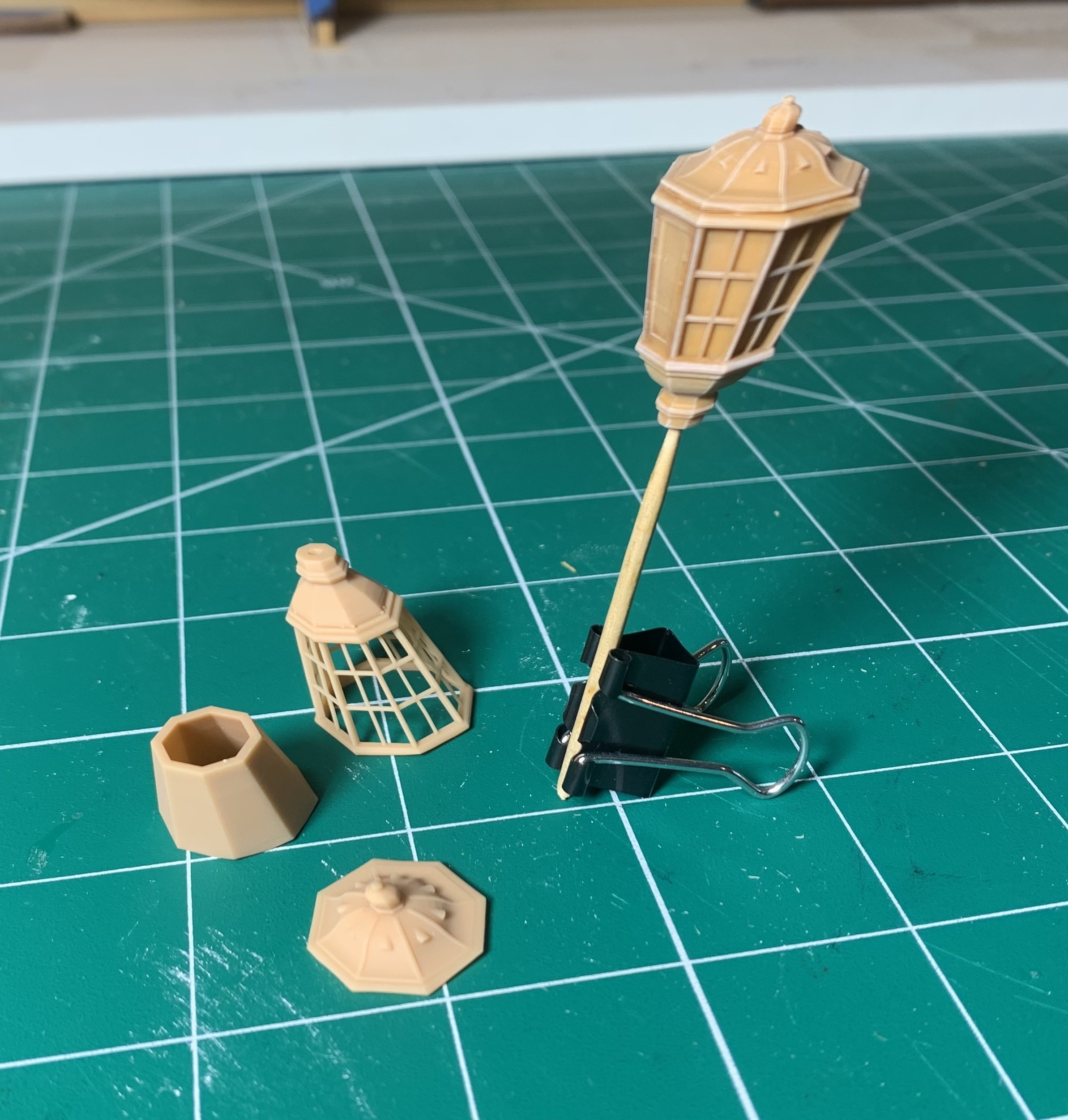
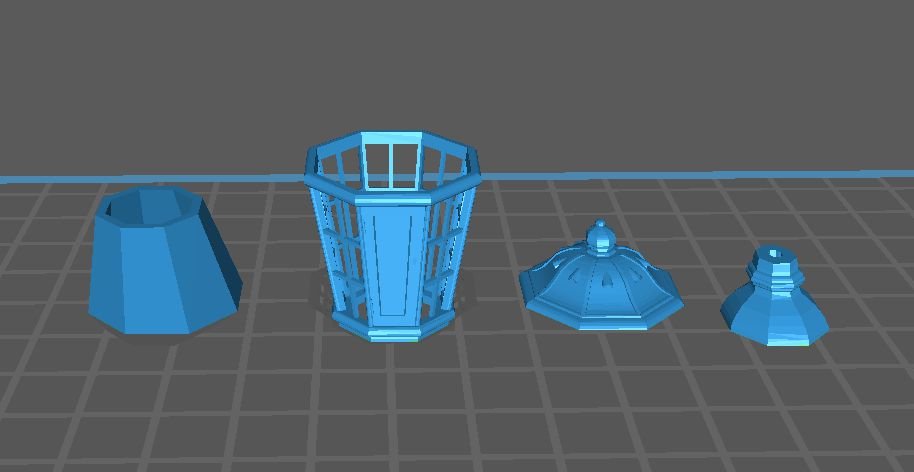
And just to keep me busy...a new Lantern...typical but detailed English Navy circa 1770-1800. I have so much to do and lots of new stuff in the works. This will be printed in four pieces if all goes according to plan. The glass will be an insert and printed in clear resin.

-
Thats what I use...I got this. It just takes time. 1.75 mm are up next.
-
Tried weighing them even with a very expensive scale but there is too much variation. I basically count out my blocks and these like a pharmacist counts pills. These are just very squirrelly. I am used to it but its a pain. Putting them on a pin is fine but that would take three times as long. I have to be quick. Too high a volume. Chuck
-
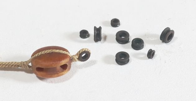
Thimbles are now in stock...only 2mm today but the other sizes will show up over the next few days...a couple of new sizes per day starting tomorrow. Packaging these things are a pain. A massive pile on the table of round items that roll. I count by two's 2, 4, 6, 8, 11....15....25 thimbles. ugh. Repeat. FYI
-
Its a wonderful wood...I use it almost exclusively except for areas that are tiny and might need extra strength.

-
Lovely work so far!! I am quite pleased with how you are making this little project your own. It should look great when completed. I just finished making another dozen of these kits. I will be sure to reference your log when my club starts building them. chuck
- 23 replies
-
- 5
-

-
- Speedwell
- battle station
- (and 1 more)
-
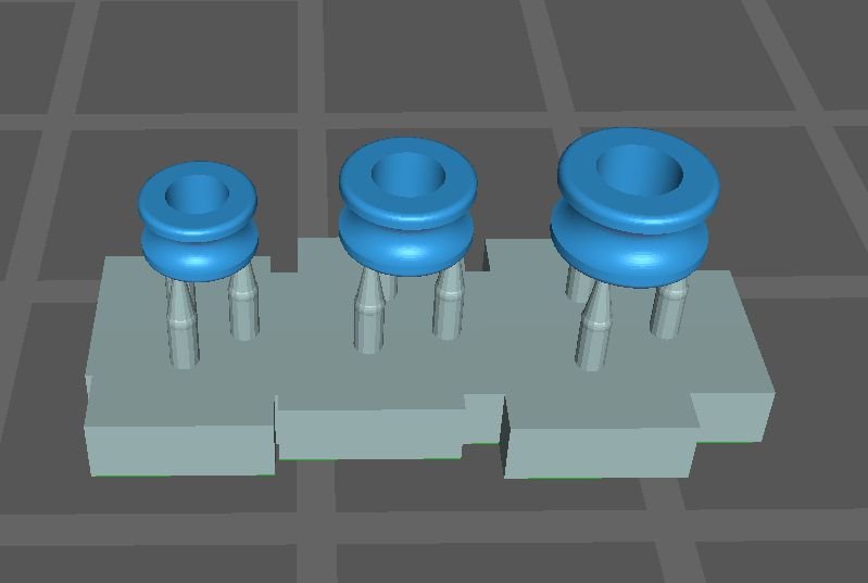
Next up.....3d printed thimbles...I hate making them so I am trying to print these tiny things. Should know by next week if they work. Black resin is the goal. Starting the test with 3 sizes and will adjust from there.
-
Beautiful work Chris!!!
-
I am gonna do some tests on 1:64 pins next week. I am about 50/50 on whether they will work. I know a lot of heavy-handed riggers out there!!!
-
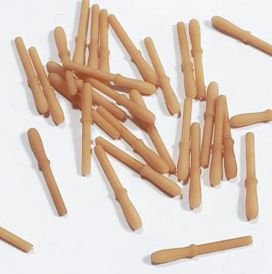
Thank You for saying guys. Some 1:48 scale swiss pear color belaying pins. Just stocked a bunch of them. I am not sure which folks will prefer but I made both colors just in case.
-
Great start...This small kit should take you little time to complete. Just have fun with it. I am busy making the second set of kits as I write this. Chuck
- 23 replies
-
- 7
-
-

-
- Speedwell
- battle station
- (and 1 more)
-
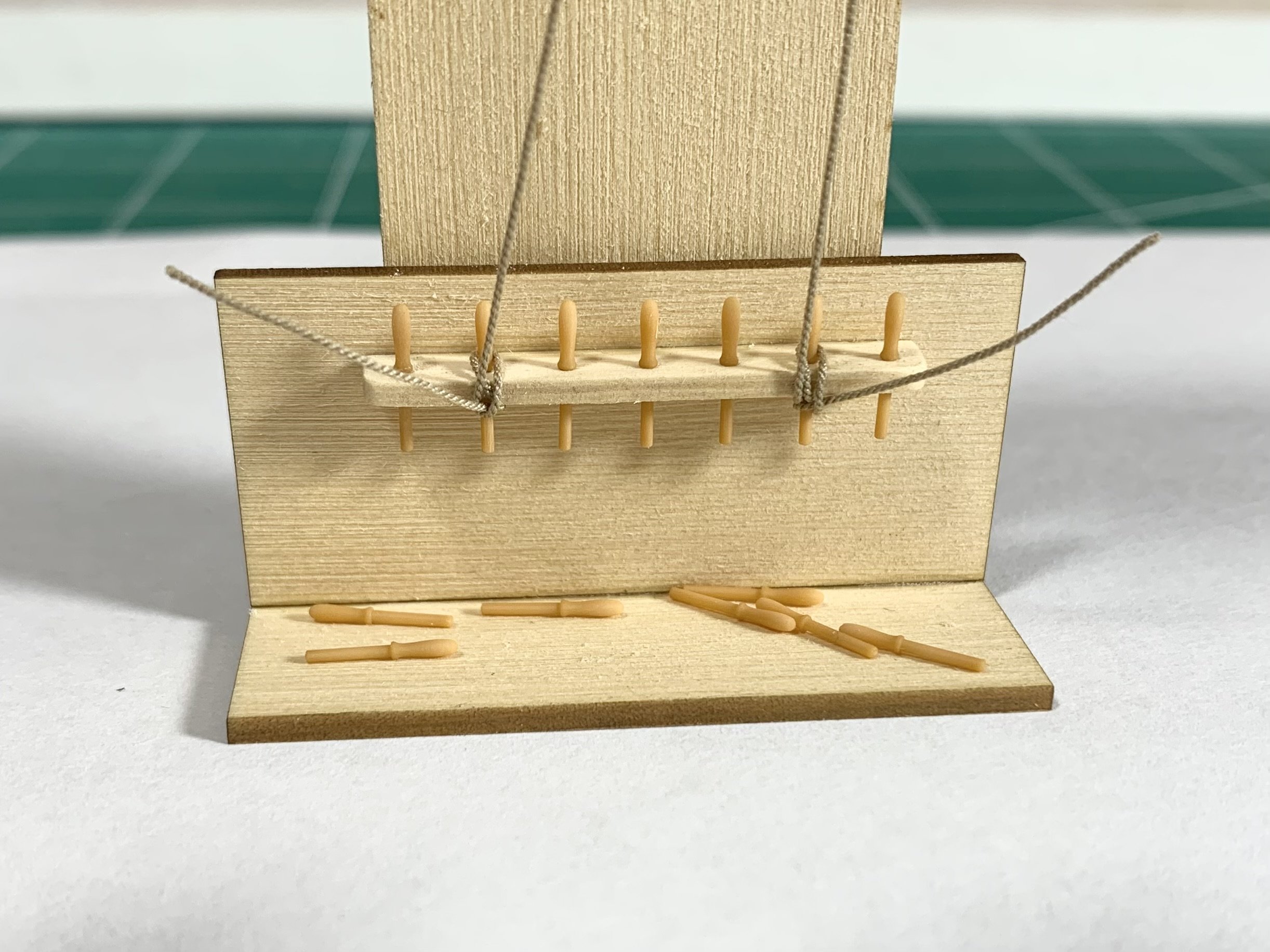
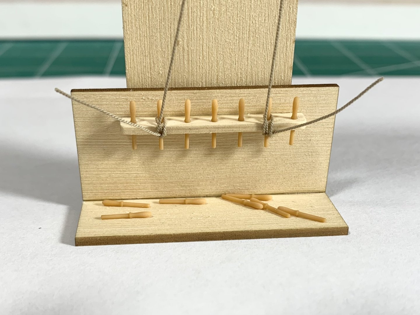
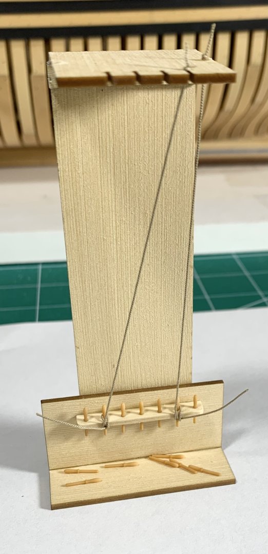
I thought some of you would want to see how I tested the viability and strength of the belaying pins. I made a crude mock up which you see below. This allowed me the opportunity to test in actual use various belaying pin iterations over and over again. I must have tested so Many different resins and resin mixes until I found the correct mix of two that would be strong enough and look good. There is no glue holding the pins in the rack and they are press fit. There is also no glue on the rope. This is the way I actually rig my models. If a pin breaks you can easily remove it and insert another although I never came close to breaking one. They will flex if you over tighten the line ridiculously. But normal rigging tension works wonderfully. These are 1:48 scale belaying pins. It actually is very encouraging and may also test 3/16” scale pins as these worked so well.
-
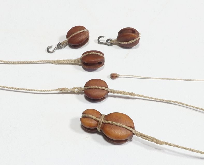
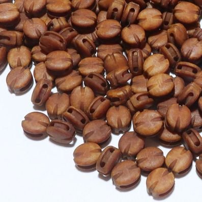
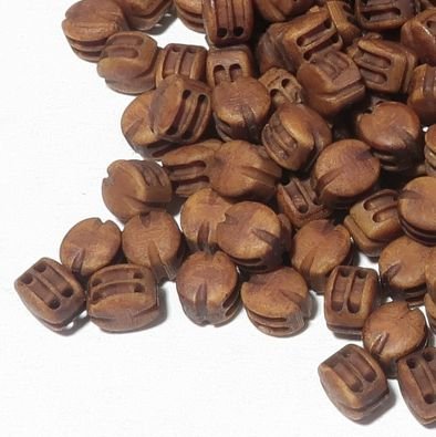
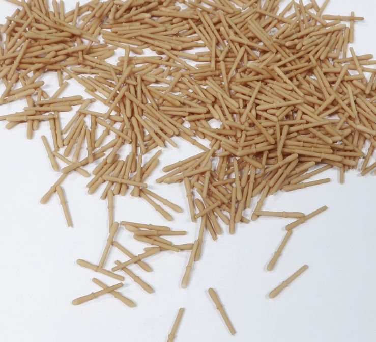
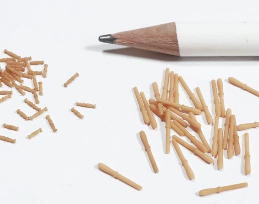
For ships much later in the 18th century for examples...toggles were used to secure blocks under the top. They are also used in other places but are usually too tiny to make and have look good. Even with 3D printing these 3mm toggles are a bear to make. They just get all over the place and its impossible to keep them on the sprues at this size. But I am getting the hang of it. Chuck
-
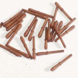
While restocking rope I am trying to take advantage of the downtime to finally make some new stuff... Belaying pins...9.5mm and 14.3mm And some teeny tiny toggles. 3mm, 4mm, and 5mm long To begin with just the boxwood color. The belaying pins are in no way as strong as brass. But they are plenty strong enough as long as you dont over-do the tightness....which you shouldnt be doing anyway. The toggles are also quite resilient. Pictured are some tests in 3 and 4 mm long. So look for them on my fittings page when I reopen next week.
-
Its gonna be a few days. Its always first come first serve. Have to get some stuff made and on the shelf first though.
-
I dont think so. Most of the orders are from the USA and domestic. So it doesnt really matter. Of the 36 orders from yesterday only 5 were international. 2 from the UK, 1 from Canada, and one from the Netherlands and one from Germany. Yes my costs are going up for almost everything but I am trying to hold off on raising prices if at all. I havent raised any prices yet. Having said that...My AYC wood costs have almost doubled. My resin costs are up slightly about 15 to 20%. I just bought a crap ton of boxwood so I will hopefully be good for a while. That was only slightly up as well. Those are my biggest material costs. Other materials are up 10 -15% on average. Not a good thing at all..... But my prices will remain the same as long as I can keep them that way. At least through the summer and into the fall. Unfortunately I have no control over the Tarif tax if you are buying from outside the USA. Its a shame and not great for small businesses like mine. But out of my control. Chuck
-
Well, LOL...you guys actually managed to do it. I thought it would have been impossible. You cleaned me out...literally every package of rope and every package of blocks...swiss pear that is. At 1:45 PM I had to call it, a $620 order for rope from a great customer in Germany. He cleaned the shelves empty of what was left. Approx. 3600 linear feet of rope. Unfortunately this means I have to close up the store to restock. Otherwise they literally sell out as quickly as I can make them. I need to build up some cushion in my inventory so I dont have a heart attack chasing orders while open. Its springtime...its beautiful outside. What are you guys doing cooped up in the shop buying so much ship model stuff? Get outside in the garden and enjoy the great weather, LOL. Seriously though, thank you so much....and sorry about the delay. I am working on it!! Lets see, I think I am working on 5mm pear deadeyes currently and .018 brown rope...a long way to go. I am not going anywhere and I am NOT going out of business, there is no pandemic...so I have no idea why or what seems to be happening. Its mind-boggling to say the least. Crazy

-
It is not a beginner model but it is certainly a challenging Intermediate project. But being the designer it may be hard for me to tell and you are best to seek a builders opinion. On the size...the Winnie is much larger than the three other kits you mentioned. Both in scale and actual size. Chuck
-
I honestly dont know. Because its on the buyers end I wont know until someone tells me. So if anyone out there has some knowledge. I think until May 4th anything under $800 is still good to go but after May 4th its anyones guess. I shipped a few to Canada yesterday and today so maybe will know shortly if those folks let me know. Chuck
-
They are on the honey-do wish list!!! So much to do and just impossible as one person. But yes eventually. Chuck
-
I opened the online store yesterday and at the time was nearly fully stocked. But in two days I have seen a huge upswing in sales....huge. I am not sure why. Maybe the tariff situation but I really dont know. Maybe from folks seeing the rope and blocks at the show? Anyway, I just want to let folks know I am diligently making more blocks and rope...but its going to be a slog. I am down to nearly nothing left in stock right now. I will be working as fast as I can so thank you for your patience. The "swiss pear" colored 3d printed blocks in particular are literally flying off the shelf. The more folks see and use them, the more I sell. I have all my 3d printers working full tilt. Again thank you for your patience.