Chuck
-
Posts
9,052 -
Joined
-
Last visited
Content Type
Profiles
Forums
Gallery
Events
Everything posted by Chuck
-
 Very nice work. Coming along wonderfully!!!
 -
That rigging looks very impressive...wonderful work on that. I am glad you are having fun with it. It is quite challenging but very rewarding too. Chuck
- 1,668 replies
-
- 1
-

-
- syren
- model shipways
- (and 1 more)
-
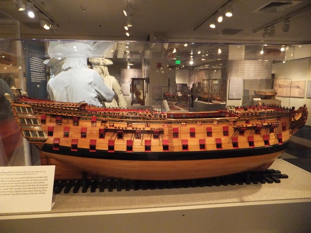
Many contemporary models and admiralty models were not POF either. The method of construction doesnt really matter....its the end result that matters..... Unless you really want to build a ship model as it was actually built, or leave the hull unplanked to reveal framing.....there is no real difference in the final outcome. It just becomes a matter of your preference. Which method are you most comfortable with? For those folks that might look down on one method over another for some silly reason....that is a something they must deal with as it is usually just an attempt to make themselves feel better. Here is a perfect example......does anyone want to guess how this hull was made?? Chuck

-
No not at all...I rub the edge of a sharpened pencil down the edge of the plank and it works fine. You could even use a fine sharpie if you are careful. Chuck
-
I started using this stuff. Works great. http://www.browncor.com/product/B41838.htm?utm_source=googleps&utm_medium=GPS&utm_campaign=GMerchants Chuck
-
By the way....shall I move this to the group build forum....I almost couldnt find it again after first looking there. Chuck
-
Good start...but the spacer blocks you are using look very thick. Those may be tough to remove so you can snap the bulkhead centers free. Chuck
-
You are correct...the upper part being the transom and the lower curved part being the counter. On larger frigates that small band above the counter is angled an extends to become the base of the quarter galleries port and starboard. This was what I was unsure about. I was mistaken now that I see the plan. Rattlesnake didnt have any quarter galleries so I was questioning if it was indeed flat and part of the transom. Based on the plan you show it clearly is. This two pieces of decorative molding that define this area makes it hard to see when looking dead on at the stern. But the profile drawing you show makes it clear that this is a flat area of the bottom of the transom. I wonder if the two pieces of molding were an attempt to make the privateer appear like a larger frigate or if it was merely decorative. Having no quarter galleries would make this tough to pull off such a ruse. I would still plank it as Hahn did with the p&S planking overlapping the counter planks. I hope I didnt confuse you with that. Chuck
-
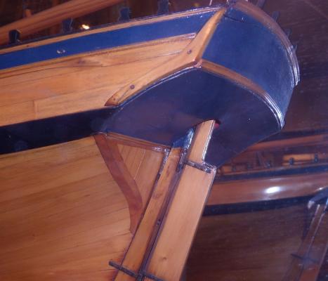
Hahns Rattlesnake...Planks overlap the counter planking. You will also see on most ships like this that there are two counters. An upper and a lower under the transom. I am not sure if the kit simplifies this or if it is in fact a flat area on the same plain as the transom. simply a decorative design. My guess is that it is a simplification for the kit so the one piece cast transom can be utilized. I dont have a copy of the rattlesnake plans to double check...But even if the upper counter was relatively flat I would think it at least angled differently than the transom. Less than normally seen on a ship of this type though because there are no quarter galleries.. Its hard to say without the plans in front of me. BUT...totally unrelated and based on what Druxey has shown. The cutter Cheerful I am working on has this feature of a rabbeted fashion piece. . Its going to be quite a challenge to model it. You can see it clearly in the photo below. This would not have been the case on rattlesnake however based on what I have seen of her.
-
Wonderful job. That model is really shaping up.
-
Well done sir.....Chris that is an excellent model and kit design. And WELCOME BACK. Chuck
-
Its not just the cost issue but that is a big part of it. Its also the ability to get enough of the other wood in significant quantities. Consider the amount of kits that are sold each year. Thats a lot of wood. I suspect that if a kit MFG were to open in South America. You would see boxwood being used. BUT the mfg's in North America have a plentiful and inexpensive source of wood with basswood. Chuck
-
Will do......an announcement will be made right here on MSW. Chuck
-
Very nice images of the frame centers being removed. That shows how it should be done. Nice update. Chuck
-
We would have a look at them and then decide whether to replace those offending cant frames. Other than that we wont post another wntire set of drawings. Just a fix for those that may have been created with errors. Chuck
-
Dont use the gallery to upload your images...that is for completed models only. Use the upload tool on each post. Edit your posts and use teh full editor to add the pictures again. DO NOT USE the gallery and then link them into your log. That is a NO-NO. Chuck
-
Yes I would still only put one. They will get pretty narrow. Here is a site that shows teh Mayflower II being planked. Read through all of the months of construction to see the planking being fixed. There are some good pictures. There were no drop planks at all on teh replica. I would still say its Ok to use one at the bow though. Directly beneath the wales. http://blogs.plimoth.org/captns-blog/?m=201301 Chuck
-
I have seen six pounders that were 9 feet long. For teh small cutter I am working on, they were only 6' long. There were no standard one size fits all. Chuck
-
Thanks Guys....Just have to get the yardwork done first.... I hate yardwork. Chuck
-
Yes the 12 pounders would work for the long guns but I dont have any carronades for sale. Blocks will be ready over the summer. Chuck
-
In most cases both...but only one drop plank at the bow usually. Chuck
-
Drilled and filled....they are just simulated treenails. Chuck
-
Some great looking progress. The transom came out beautifully.
-
Uri....its great to see how you built the pump. I held them in my hands at the show and they are a marvel to look at and feel. The "pump-action" can be felt when you move the crank. Thank you so much for posting. I cant wait to see them on your brig. You should also start a build log for the entire project. I hope to see you again real soon. Chuck
-
Thank you very much Christian.