Chuck
-
Posts
9,703 -
Joined
-
Last visited
Content Type
Profiles
Forums
Gallery
Events
Everything posted by Chuck
-
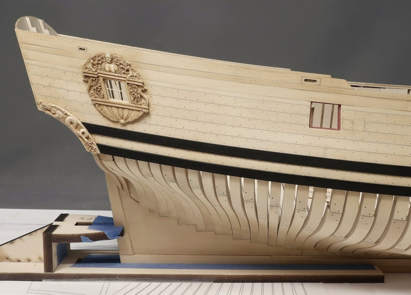
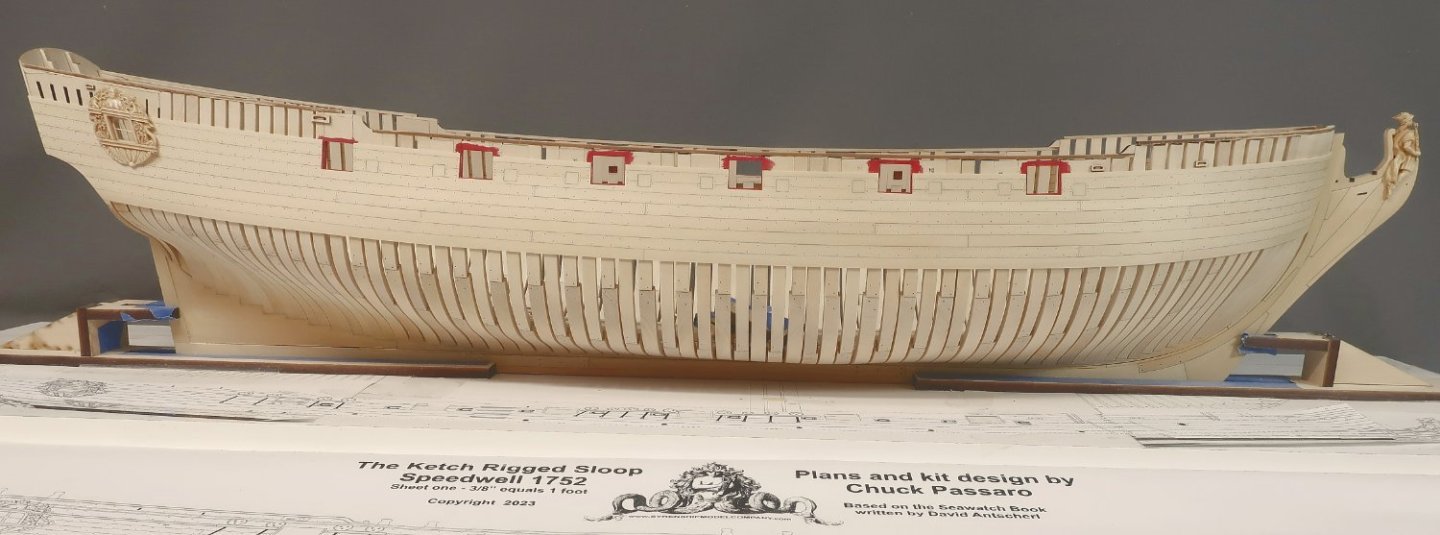
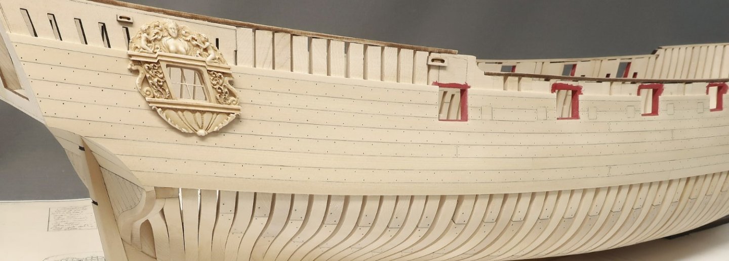
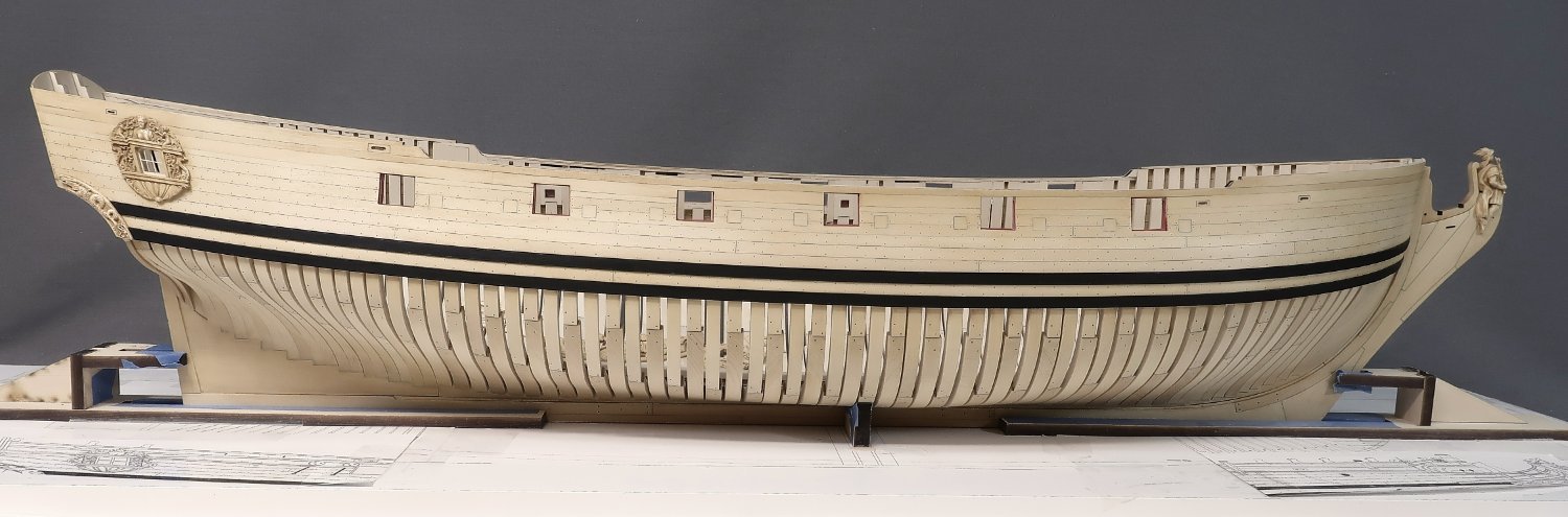
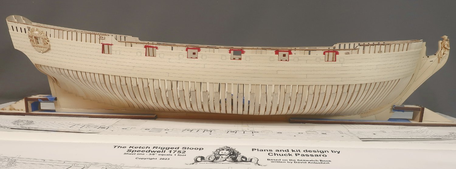
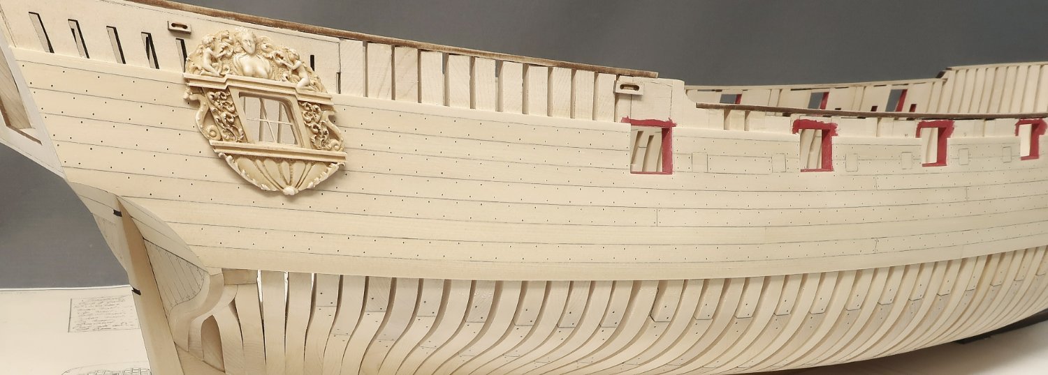
 Thank you guys for saying... In preparation to install the second layer for the wales, the carved fashion piece was added first. This is a resin casting prepared in the usual way with gel stain. Like I did for the Winnie carvings. It is easier and cleaner to add the carved fashion piece first rather than have to cut and shape the back side to fit over the wales. I will add the fashion piece first and then just butt the wales up against the forward side next. The resin carving will bend to conform to the hull shape. No worries there. I glued the lower end in first and waited for it to dry using CA. This locked in pretty good so I could then push the top end of the fashion piece to bend it and secure it with CA as well. I filled any gaps with filler but there shouldnt be many. It should fit pretty tightly. Note that the QBadge is still just temporarily tacked in position. Its not permanent yet. Then I added the second layer of the upper and lower wales. I used 1/32" strips of Yellow cedar. You could use 3/64" thick strips as well but I am personally partial to thinner wales. I did knock-off the top and bottom edges of the wales to just soften them up. No hard edges for me. I also painted the top and bottom edges black before gluing them on the model. This keeps it nice and neat so I dont have to try and paint that edge on the model. It makes a big difference and its finally starting to look like a ship model!!! In addition to softening the upper and lower edges of each wale strip before gluing them on, I also tapered the forward end thinner. It should diminish in thickness to a thin almost knife sharp edge going into the stem. The taper started about 3/4” from the forward edge. I sanded it to a thin pointy forward edge so it appears to enter the rabbet as it should based on contemporary practice. It should appear to be the same thickness as the other planks entering the stem rabbet or nearly so. Then I proceeded to carefully paint the top layer for both wales strakes completely black. I use Utrecht Brand Acrylic...Mars Black this time around. Take your time with this and do it neatly because its a huge part of the overall look and feel of your model. I also finally added the finish to the model using wipe on poly and some "Old Masters" fruitwood gel stain. Up until this point there was no finish applied. This gives the wood a nice natural brushed appearance with some deeper color that I like. The cedar looks great after this application in my opinion. Wipe on poly was added first...then some gel stain. The gel stain was wiped off immediately after applying it so it wouldn't get too dark. By "re-wetting" again with some wipe on poly, and buffing it off you can achieve a nice "brushed appearance". It doesnt look too sterile or yellow in case you want a different look. I wanted to try something different this time around. Just compare the planking and frames in these photos with those in my previous post to see how different they appear. It is subtle, but you can see the difference. Next up some fancy molding....and odds and ends.
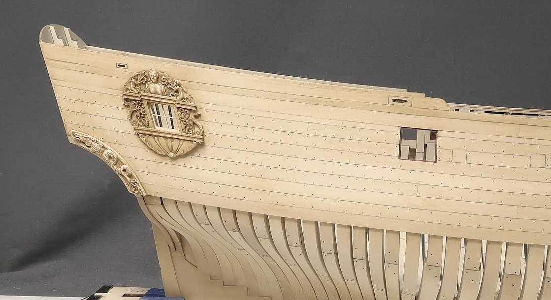

-
Mike...Looking great. Cant wait to see you start making progress. I have seen some of Mike Shanks progress on the development of this project...happy you started a build log here. Allan...this is just a small group of model builders that got together and made a few kits for their little group. It is not a commercial kit. There are about a half dozen participants, maybe a few more. I think Pat...Banyan is also building one but I am not sure. Hopefully he will start a log as well. Chuck
- 47 replies
-
- 3
-

-
- Fubbs
- Weasel Works
- (and 1 more)
-
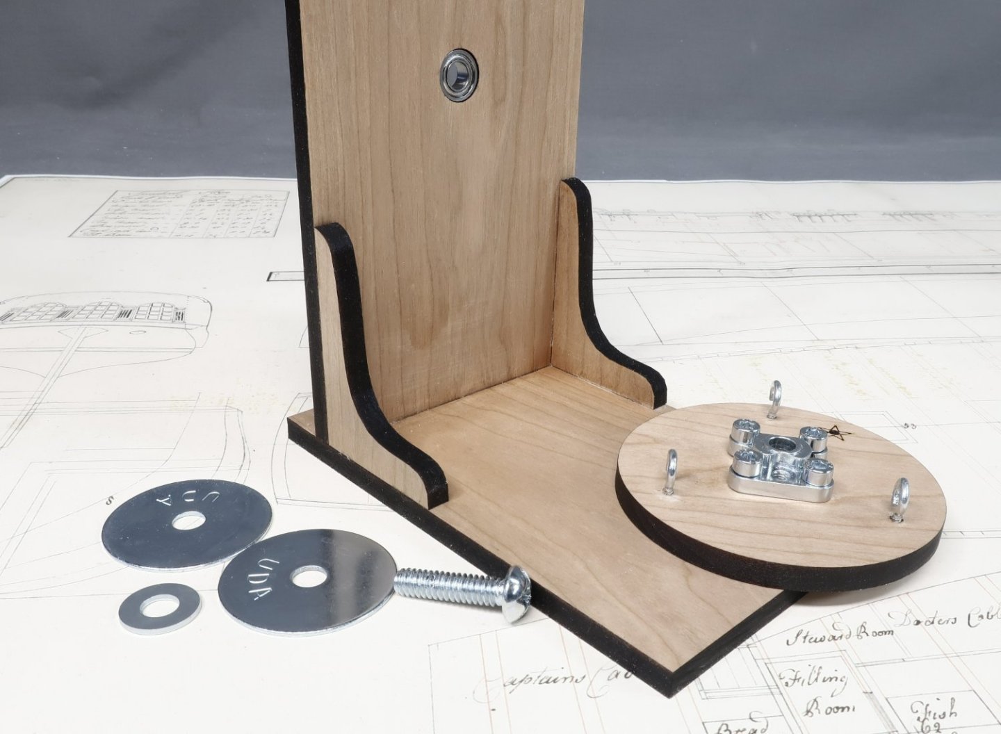
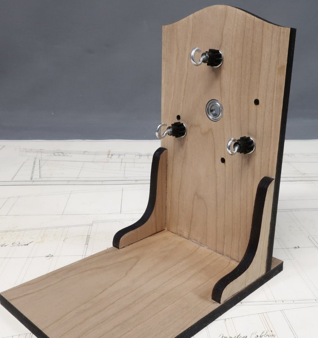
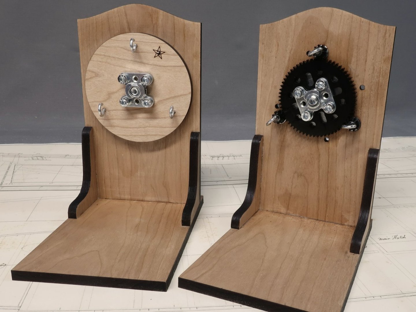
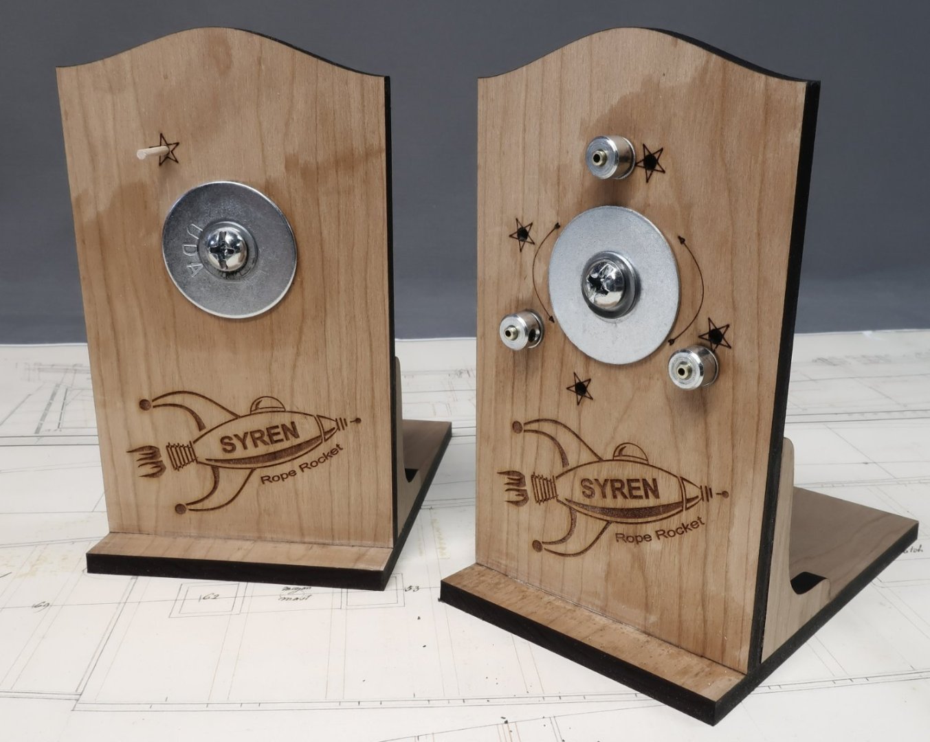
Some of you guys may have noticed the announcement on my website about the ropewalk availability. Its been a while. Long story short, yet another supplier who discontinued making all the gears and all of the hubs and hardware I used to make the ropewalks. No warning...they just discontinued them. But fear not....I have sourced new gears and hubs and hardware. Of course they are a different pitch diameter and with a different hole configuration etc. Basically I had to redesign the entire ropewalk. It is essentially the same machine as the size of all the parts just changed. But new drawings and files were needed. I did make the Rope Rocket a bit taller in this new version 2.0. I also added some bearings. This makes for a quieter machine and imagine it will also extend its life. Although nobody makes as much rope as I do on these things. In fact I am still using my 8 year old version 1.0 machine and its still kicking after hundreds of miles of rope. I am putting the new version 2.0 Rope Rocket through its paces right now. Its all going rather well. Like I said its the same basic machine. The gears are about 2mm larger in diameter this time. Here is a pic of a freshly made machine. I must write new instructions. You can still swap to a 4 strand rope as well just like the original. These two pics show the bearings in position which makes for a smoother ride. So if you were waiting for the new V2 Rope Rocket, it wont be long now. I just have to write the new assembly instructions and make a bunch of them. Same great taste!!! You really wouldnt notice any change if you dont have both versions. Makes pretty fantastic looking rope....same operating instructions. slightly different assembly instructions. The downside....its $8 more expensive than the original version 1.0....Of course it is, LOL That just couldn't be avoided in this day and age. Supply chains is a real tough nut these days. And yes I kept the fun imagery of the Rocket on the back side of this version. I didnt bother adding a finish to this v 2.0 test but its the same beautiful solid cherry. Maybe I will give it a coat of wipe on poly....but mine will get bloody filthy in a few weeks anyways. So it doesnt matter.
-
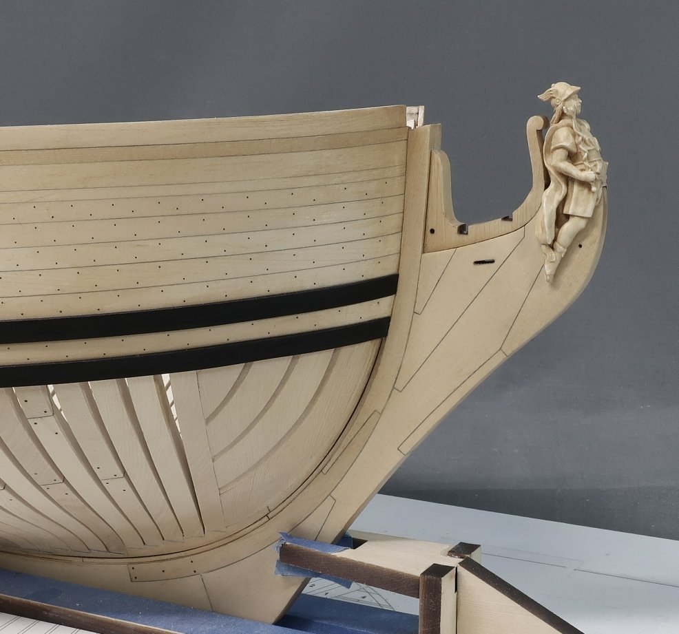
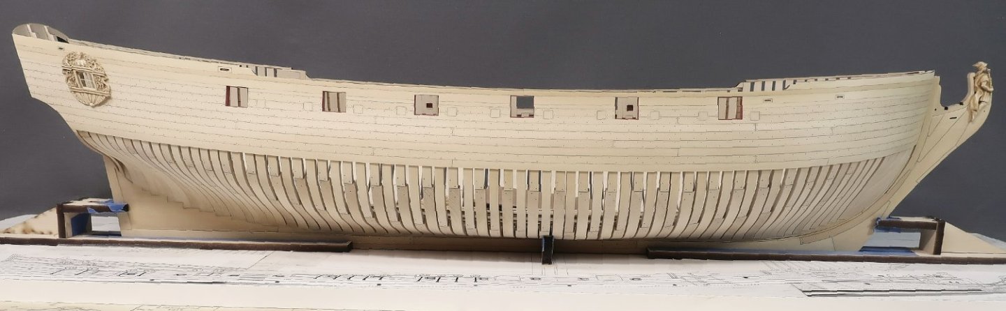
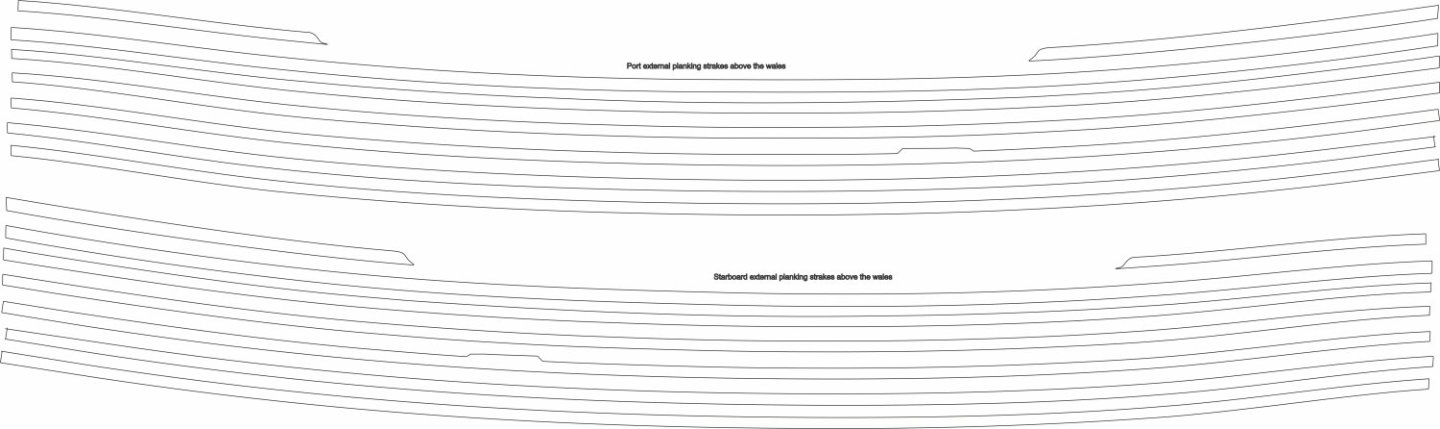
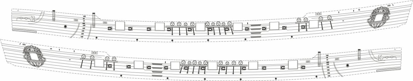
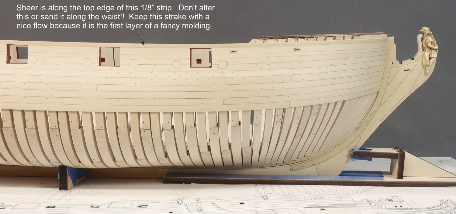
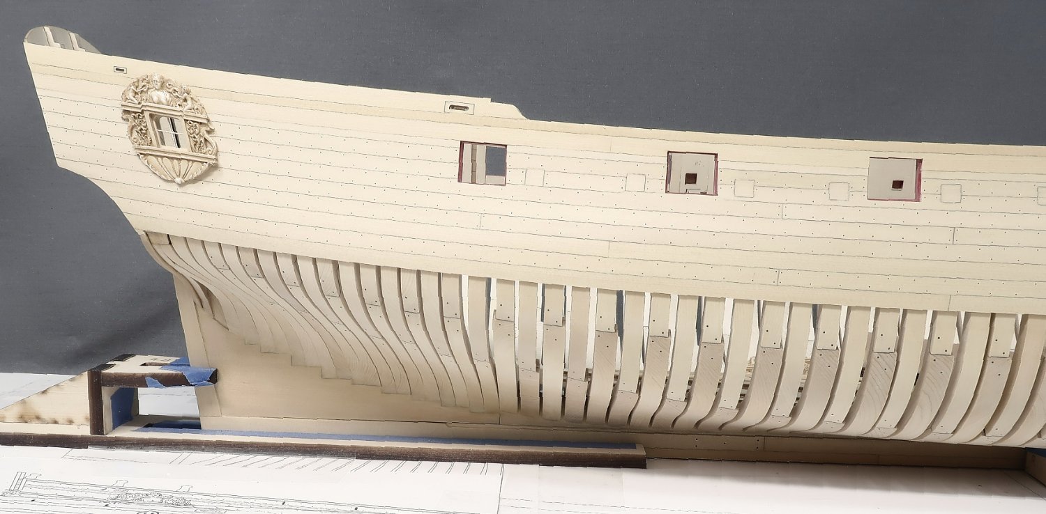
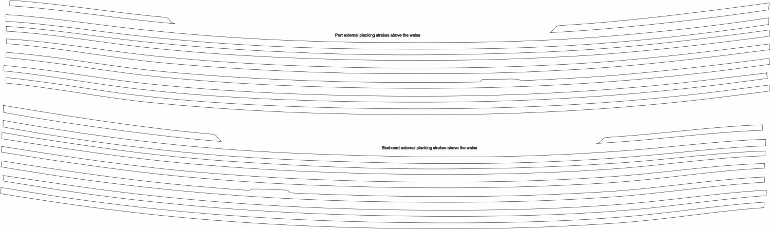
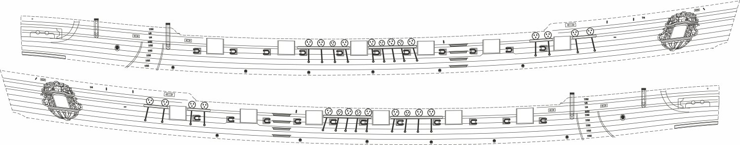
After finishing the treenails...finally, I continued to plank up to the sheer. This meant one more 1/4" wide strake to cut around all those ports. It wasnt too bad to do. Then another stake of 1/8" wide planking which is the first layer for a fancy molding strip. We will add that soon. The top of this 1/8" strake and molding is the sheer. The top of this along the waist should NOT be altered or sanded down. You want to maintain that ice continuous and graceful flow for that molding strip and sheer. If for whatever reason your planking in the waist ends up slightly higher or lower that is OK. This is tough to plan out exactly. The top edge for me along the waste was about 1/64" higher than the sheer I sanded into the framing and fairing cap. Thats is perfectly fine and it is best not to sand the strake down to match. Best to keep a nice flow and even width to what will become a molding piece. Hope that makes sense. Then I planked along the drifts fore and aft to complete the external planking on the starboard side. I will repeat this on the port side next. The Qbadge and window for it are just lightly tacked in place for the photo. That wont be glued permanently yet. Note where you would see the scrolls along the waist. On Speedwell they are different than on a frigate like the Winnie. Therefore a different approach is needed with them. So you will notice how the planking drifts along the waist are stepped. This shape will allow for the addition of the scrollwork later where it will make perfect sense. Once I complete this on the other side I will begin adding the second layer of the wales painted black and the fashion pieces. Then the fancy molding will be added outboard. All of the planking should be relatively easy. Aside from the detailed expansion templates (below), I also created an expansion of every single planking strake above the wales individually. They have the tapers needed on each of them. This can be used to literally cut the exact shape of every strake from a 3/64" thick sheet of Yellow Cedar if you chose to. Even the drifts are included. You will still have to cut them around each gunport and break them into individual lengths depending on where your planking step pattern is. You can use the plans to find those. There was no need to create an expansion drawing for the 3/32" and 1/8" wide strakes that represent the fancy molding. I just ripped those on my table saw as they are not tapered and easy to plank with being so narrow.


-
Its bot braided line. The brand is sunset Amnesia. I am not sure about the material. I dont think it matters. Just has to be smooth and consistently colored.
-
Not yet…I want to get well ahead before releasing this this. Nothing worse than having folks waiting on me for their next chapter.
-
A number 78 drill bit. Although one could use a 79 as well. Its more fragile and more prone to breaking and tougher to insert the fishing line because its a super tight fit requiring no glue at all. So I started using the 78 now. Still no glue needed though. Stick the line i nto each hole…i use a straight razor to slice off flush. Sand the surface lightly with 400 grit paper after a few rows are done. Apply wipe on poly which eventually acts as a glue if ever it needed it to secure the fishing line. I almost used a dark brown fishing line but couldnt see that much difference on my tests so I decided to stick with the black. Chuck
-
It has been a little while since I have posted an update. But I have indeed been working on Speedwell. I have finished planking up to the molding level and not the sheer. I have stopped to treenail the hull planking which takes a while to do neatly and precisely. I am using 10lb black fishing line. Work has been slow because I am taking my time to line everything up with the frames and keep it all neat and tidy. The starboard side is complete, and the port side is underway. Once I am finished with this I will complete the outboard planking up to the shear. Then I will add the second layer of wales and the fancy molding. Its getting there. Treenailing is optional of course but it does make a difference when not overdone and if the treenails are not too large. Even though only a few strakes need treenails, it still takes a bloody long time to do!!!
-
Just beautiful!! Wonderful execution of those head details.
-
Looks great…adding the treenails now is fine and a good idea.
-
Absolutely beautiful. The cherry looks stunning. That is some precise and careful craftsmanship. Bravo!!!!
-
Wishing you the best with that move Ben. You will miss the snow!!!
- 399 replies
-
- 3
-
-
- winchelsea
- Syren Ship Model Company
- (and 1 more)
-
Just an FYI I am headed on a short roadtrip tomorrow. Nothing fancy…headed to Niagara Falls with the Mrs. Never been there so why not take a ride and scartch it off the bucket list. I will be closing the online store in the morning…but it will be back open on Wednesday. I should be back in my shop a few days later.
-
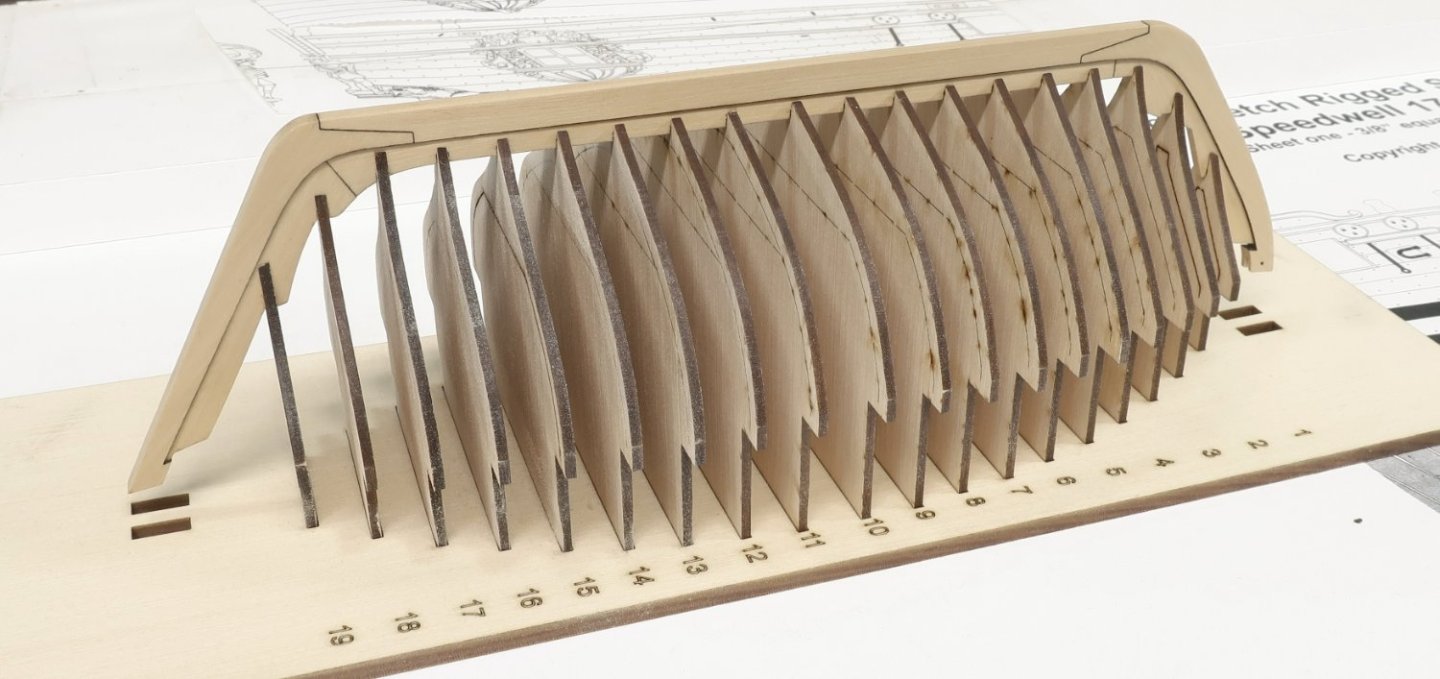
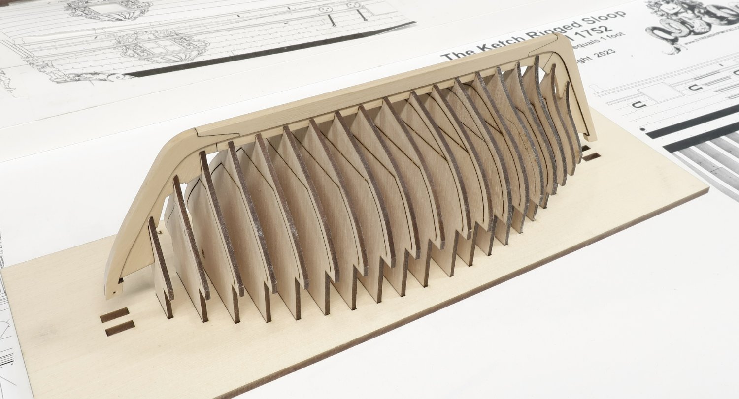
Just a quick test of the frames in position. This is all just dry fit. Everything looks great so far. I am headed away tomorrow morning on a short road trip so no shop time. But when I get back work will resume on the SOPHIA ROSE and SPEEDWELL. These boats were meant to be beached as a fun fact when room at the wharf was not plentiful. Anywhere from 2 to 5 fisherman were on these small boats. Chuck

- 16 replies
-
- 28
-
-

-
- Sophia Rose
- Block Island cowhorn
- (and 1 more)
-
The margin plank will cover all of that even if you leave the deck unplanked on one side. Without the margin plank it would look very sloppy. I dont see what the issue is. Chuck
- 389 replies
-
- 2
-
-
- winchelsea
- Syren Ship Model Company
- (and 1 more)
-
Thankyou…yes I should have them also.
-
I am getting closer .....mass production of CNC blocks...I apologize for my lack of inventory for so long but we are perfecting the process. I havent had blocks in stock for months. It shouldnt be long now. I want to be able to bring you the best CNC blocks possible at a ridiculously low price. A lot lower than you might even imagine. My rope is the cheapest available for the quality and lengths available. I am hoping to do the same with some superior blocks in Boxwood and Swiss pear. Automated so I can concentrate on my ship model projects like Speedwell. I cant tell you how long and hard this R&D process has been. So many experiments and so many failures. Successes are few but we learn from every failed batch made. I wish I could explain what goes into figuring this stuff out. Lots of time and lots of money. Hot out of the oven before polishing and tumbling. Sorry for the lack of inventory but it will be so worth the wait it I promise.

-
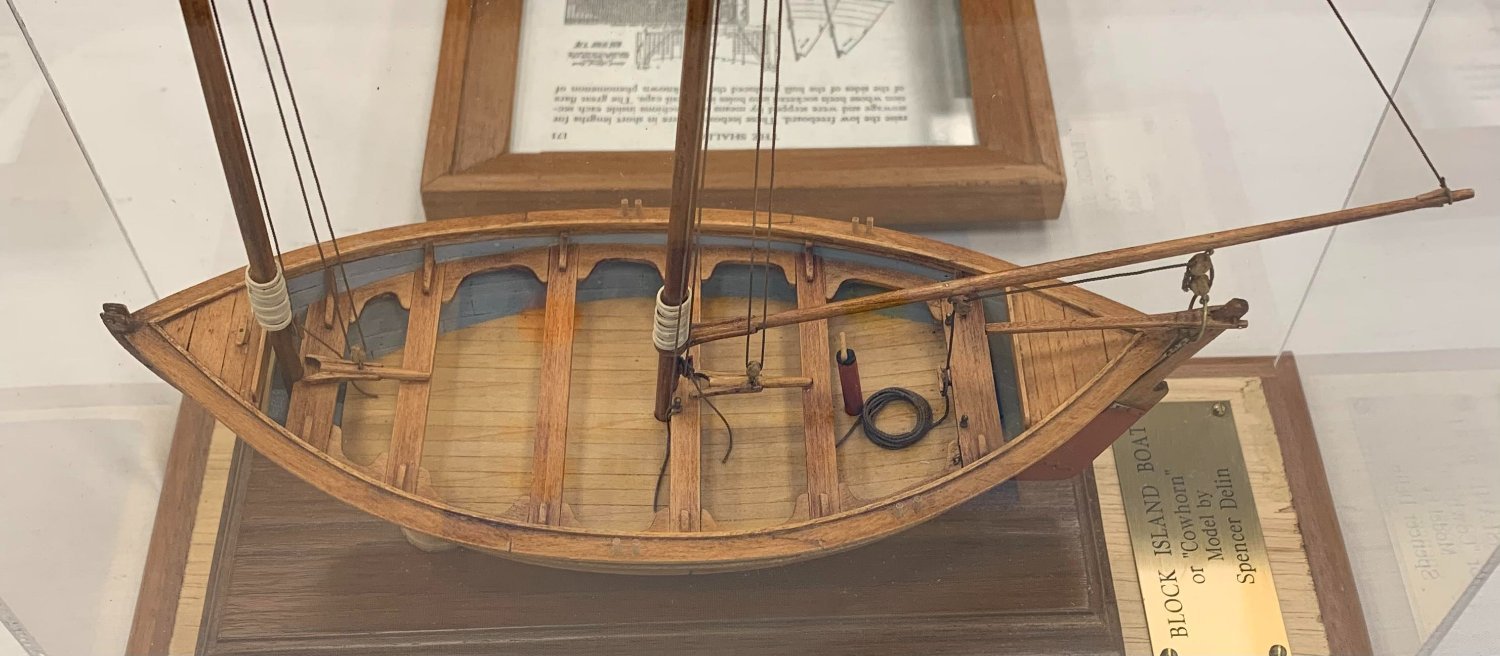
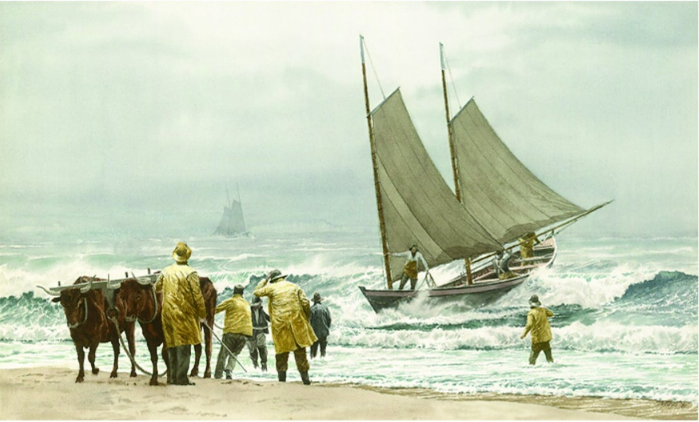
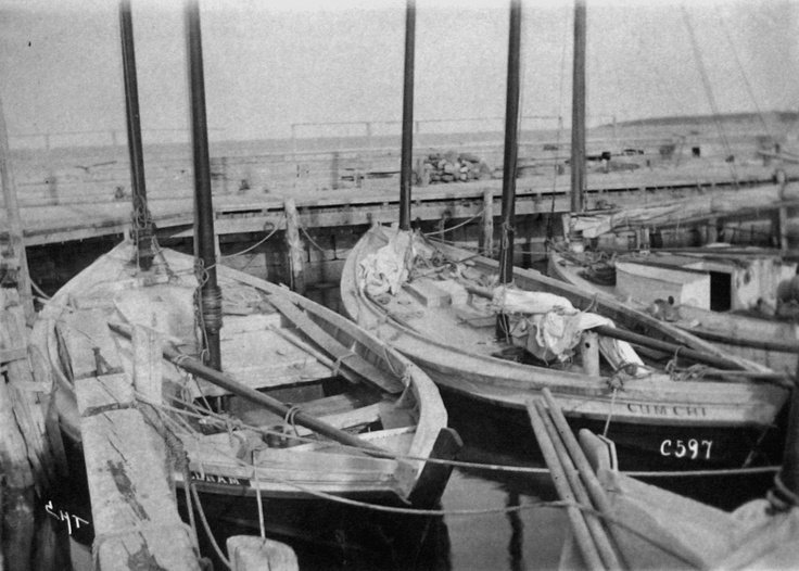
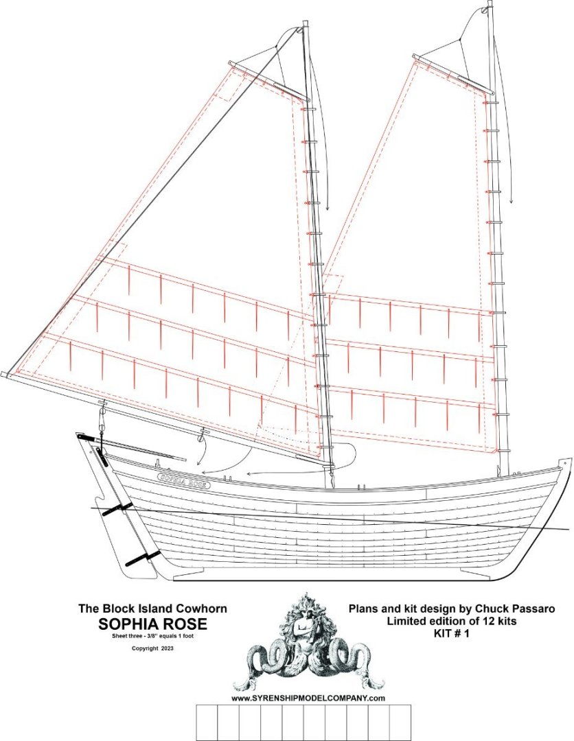
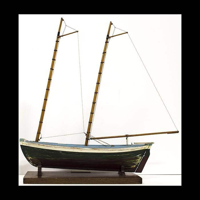
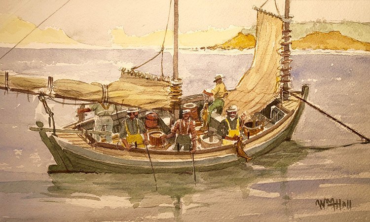
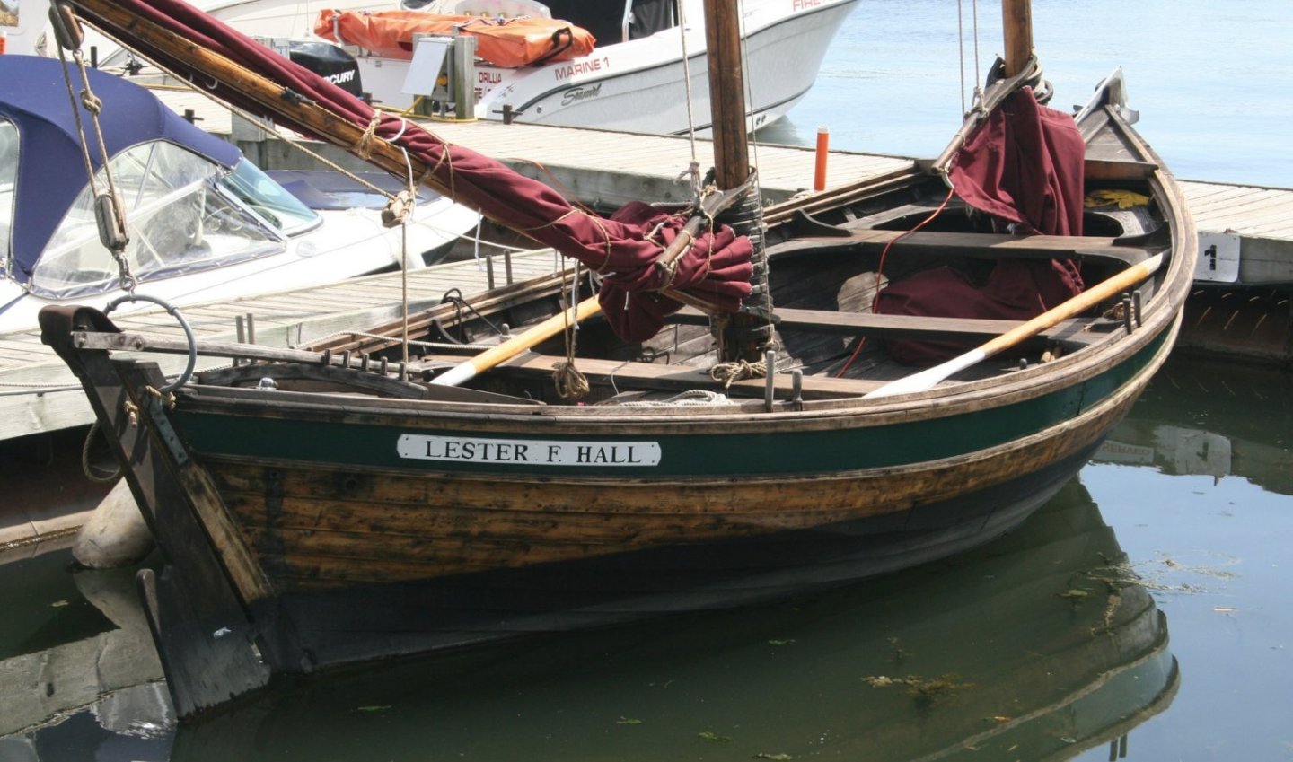
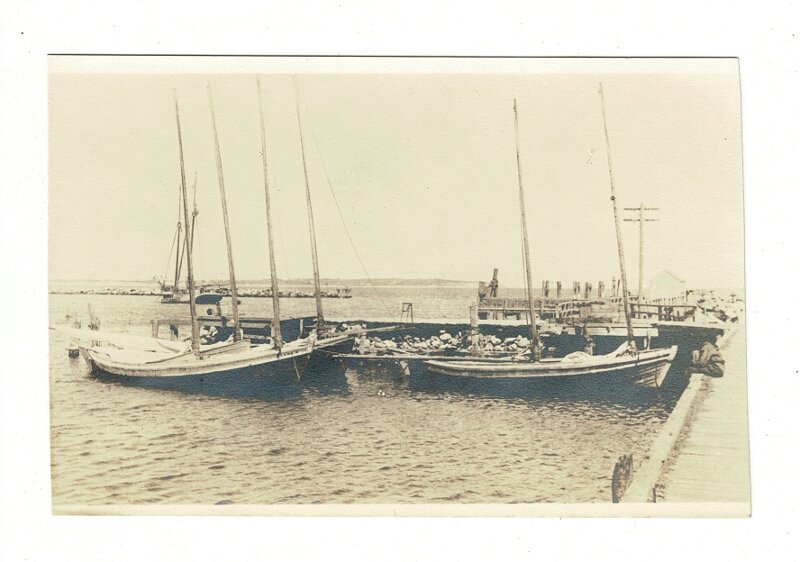
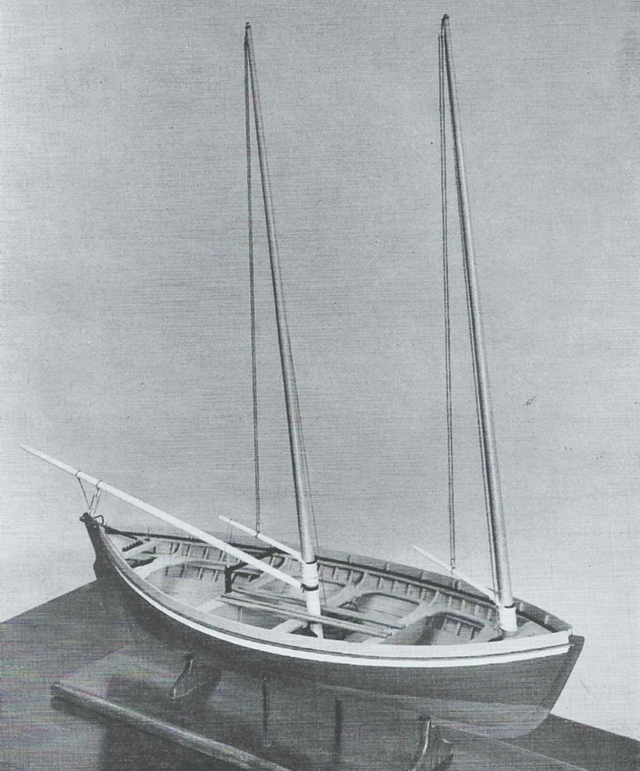
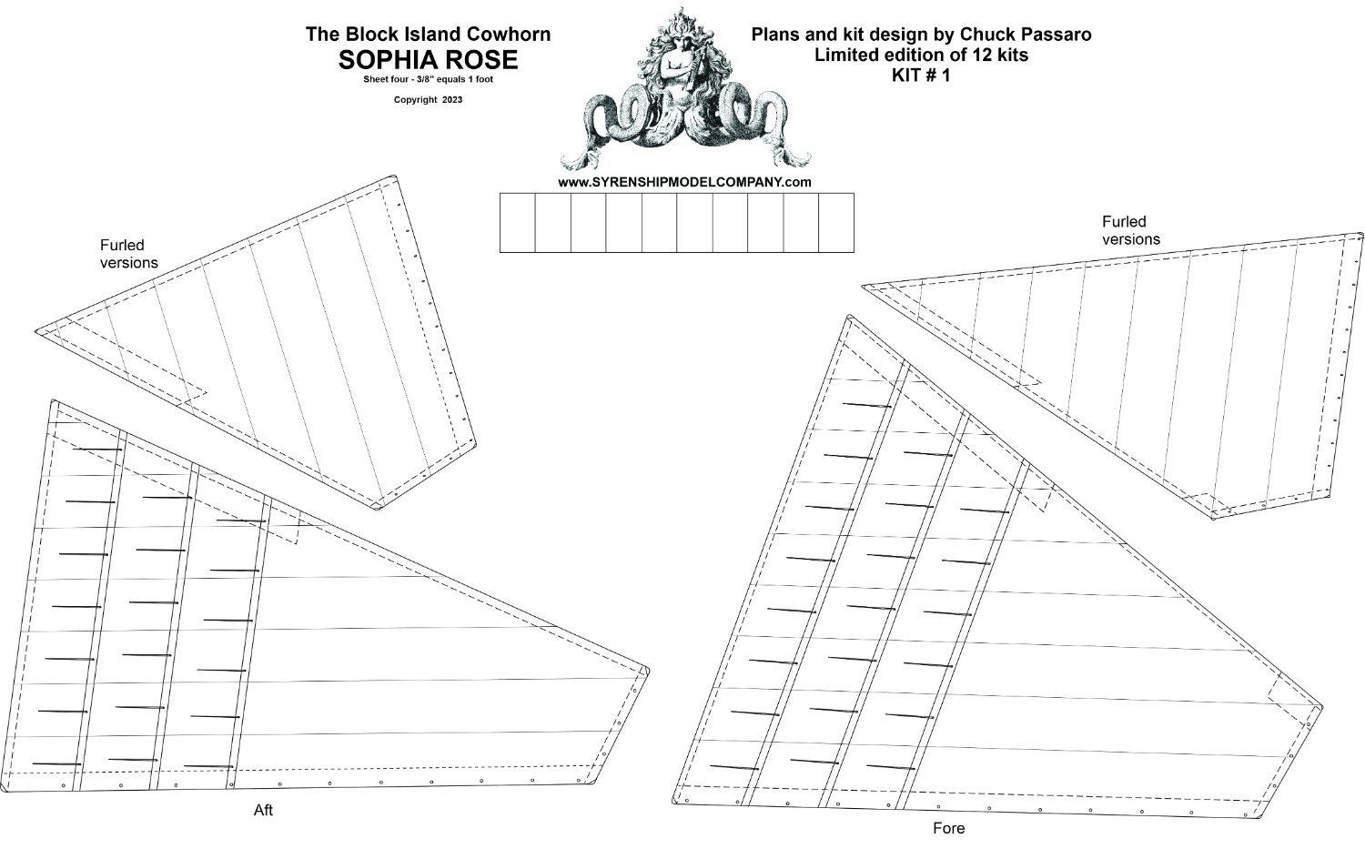
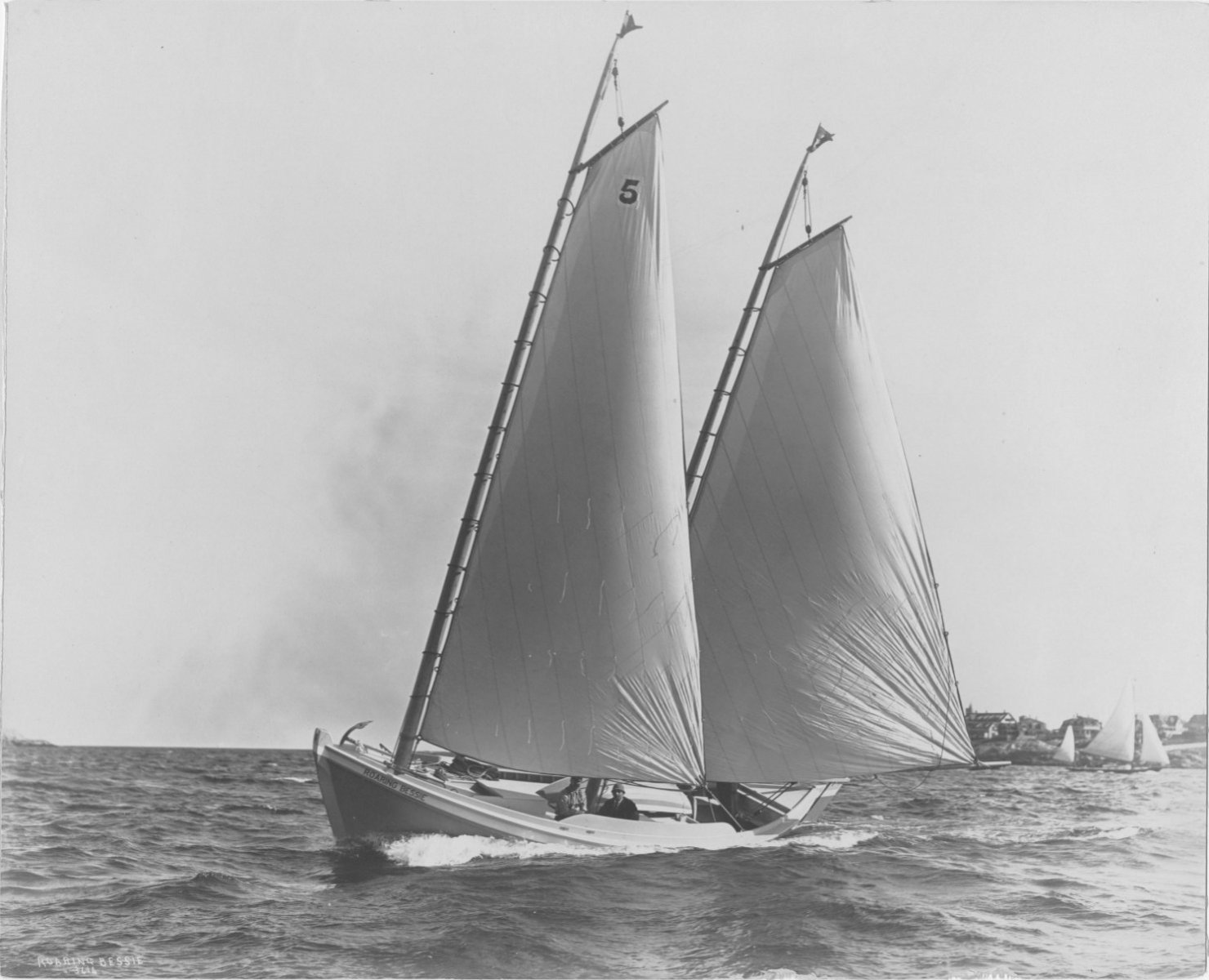
Yes I love these small workboats as well but I am really partial to smaller open wooden craft. I will rig her with furled sails but there are two other options. Here is an Alfred Brownell model of another "Block Island Cowhorn". It is rigged without sails. And also without a topping lift. Many if not most of these small boats did NOT have a topping lift. I have developed plans with a topping lift but it would be very easy to omit it but more difficult to model and show the boom in position without gluing it or pinning it. Normally it would be just left on deck as it was a workboat and they were sloppy unlike disciplined navy sailors. This model also shows the leeboards which I may also include. See how sloppy the decks were on these. The boom was removed from the mast so it could be brought in and left on top of the thwarts. The wharfs were very crowded and this made it easier to cram more fishing boats in there. Notice how they were stacked two deep in the wharf. Plans will include rigging and masting with and without sails... Including a separate sheet with sails drawn with patterns for full size sails AND furled options which are made shorter so they look in scale when furled. Another very interesting way to display these models is rigged without sails but with the bolt ropes for the sails. It creates a nice outline where the sail would be. This enables you to model it without the topping lift. Just like on the actual boat, the bolt rope on the sail raises the boom to its proper height when the sail is set. This model is from around 1900 and is in the Mystic Seaport collection. Although the twelve boxwood kits in 3/8" scale will be given away for FREE at the show and here at MSW, if there is enough interest I will certainly make more but only out of Yellow Cedar.....This may even allow me because of the personal expense to me on those 12 boxwood kits; to increase the scale to 1/2" on the any production runs, but they wont be part of the limited edition of 12 signed kits. But I am aware that there is not as much interest in these as your usual warships...but I can sometimes tire of those and this is a refreshing project for me to fill those gaps in-between while working on Speedwell. A nice painting of a block island boat showing them in use... AND an early photo of the same type but used as a pleasure boat or yacht. No topping lift on the photo. Note why they needed a leeboard....which there were typically 3 lengths from bow to stern on each side.


- 16 replies
-
- 26
-
-
-
- Sophia Rose
- Block Island cowhorn
- (and 1 more)
-
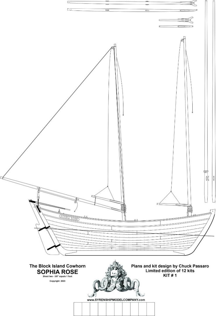
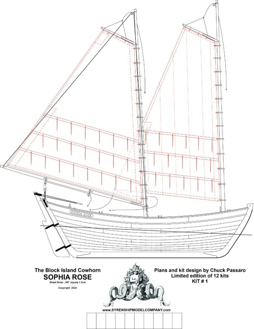
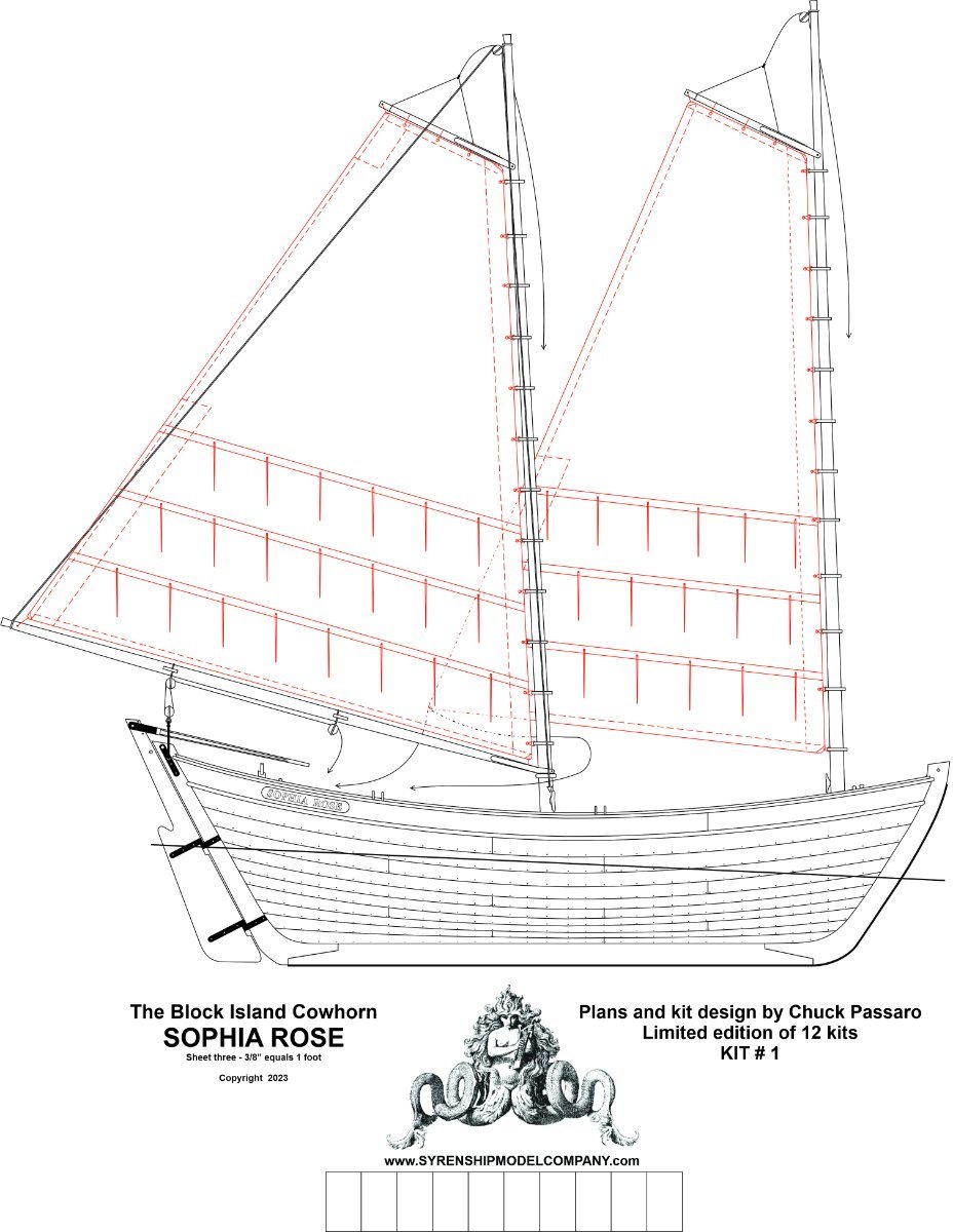
Thanks guys... Here is a look at one of the plan sheets. To show the boat and what it would look like with sails. This is the rigging plan.
- 16 replies
-
- 18
-
-
-
- Sophia Rose
- Block Island cowhorn
- (and 1 more)
-
That looks so good. My you have been busy. It looks great.
- 144 replies
-
- 2
-
-
- winchelsea
- Syren Ship Model Company
- (and 1 more)
-
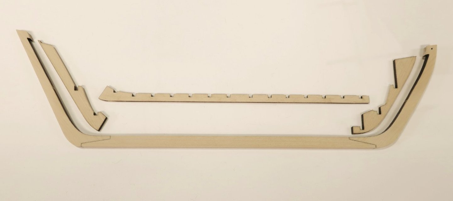
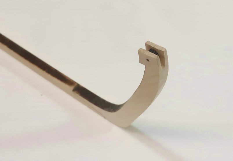
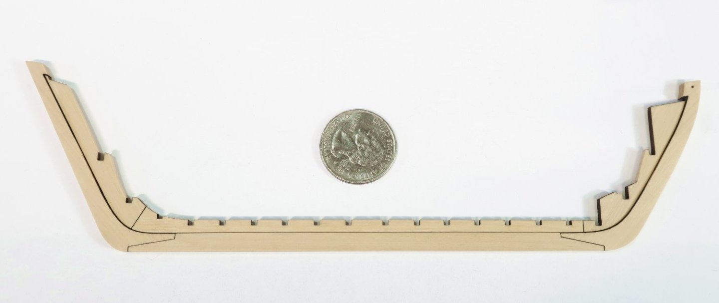
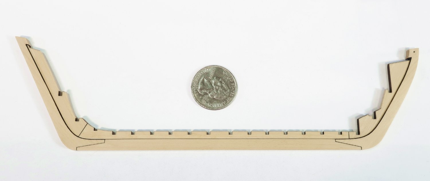
The project has actually begun.... It will be built much like the Medway longboat kit and Queen Anne Barge kits.. More to follow but this is the keel. All finished up in Boxwood. As I mentioned this will proceed very slowly. I actually have over a year to complete it. Dry fit after removing char. Basically just on the outside of the keel and inside of the notched pieces. These parts are precision laser cut so no need to sand or remove the char from the scarf joints. On the stem, there is a sheave for hauling in various lines like the anchor cable. So a slot was filed into it which was centered. I followed the plans for its depth and shape. Then a laser cut sheave was added which is actually a working sheave. Slide it into the slot and stick a length of wire or in my case some 20lb black fishing line. Thats it for now... I hope you will follow with interest. Chuck
- 16 replies
-
- 31
-
-
-
- Sophia Rose
- Block Island cowhorn
- (and 1 more)
-
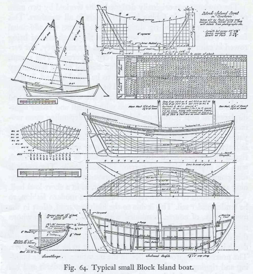
Many of you know that I am building the POF Speedwell currently. I also have several other projects underway but none of those are ready for a build log yet. These extra projects will not be updated very often and I plan on taking my time with them. This particular project is a commission of sorts. It will be made entirely of Boxwood because its a tiny open boat even at this scale. There are few models of these graceful common fishing boats out there. Thats a shame. But one I have seen and admired was made by Spencer Delrin. I have seen it many times and always said that I would build one. Now comes my chance. No two Block Island Cowhorns were alike. These were not built to a plan at all. They were made over and over again locally and each time they were slightly different. There are plans available which were made by who else but Howard Chapelle. These are the plans I am using. I have been researching them for months now. I have chosen to name this the Sophia Rose which was an actual cowhorn on block Island that was lost at sea in 1853. All hands were lost in a gail and the crew died trying to swim back to shore. There is an account of this in the Rhode Island Gazette Obituary from that time period...it was the local paper. It was owned by Barker Burnell and his brother Jonathan. My daughter's name is Sophia so I figured why not, although I wont tell her that the two brothers drowned and were lost at sea. This will actually become a limited edition all boxwood kit which will be raffled off at a future Joint Clubs conference. I will make just 10 of these boxwood kits. Five for the Conference, and 3 for MSW members.....and 2 I will keep. Although I may also release it later in Yellow cedar. The all-boxwood versions will only be made into 10 kits fully rigged. A replica which is actually very accurate.... Chapelle's Plans Spencer's Model...really beautiful...also at 3/8" scale. And some old photos as these Cowhorn double enders were used right up until the 1900's There were dozens on the Island every season (anywhere from 50 - 70) fishing. A common site from the 1820's through their prime in the 1850's and 60's.
.thumb.jpg.7787f1780f59adbb6d49b836cd98dea8.jpg)
.thumb.jpg.32bf032b4aaeed8e49d386c04f6fbaa7.jpg)


- 16 replies
-
- 20
-
-
-
- Sophia Rose
- Block Island cowhorn
- (and 1 more)


.jpg.8493a03281efaf16998fdf76293a7a9f.jpg)
.jpg.1527e47736337b2e26245ab46e65284d.jpg)