HOLIDAY DONATION DRIVE - SUPPORT MSW - DO YOUR PART TO KEEP THIS GREAT FORUM GOING! (Only 75 donations so far out of 49,000 members - C'mon guys!)
×


Chuck
-
Posts
9,674 -
Joined
-
Last visited
Content Type
Profiles
Forums
Gallery
Events
Everything posted by Chuck
-
 Really nice. Those channels look really good. Chuck
- 642 replies
-
- 1
-

-
- winchelsea
- Syren Ship Model Company
- (and 1 more)
-
Lite ply always. Just make sure it isnt warped.
-
Its a good start…
-
They will make several master molds from the masters I send them. But at some point I will need to send them more masters. I have plenty. But I am only tweaking one set for now. It depends on the shapes and how deeply the undercuts and stuff are for how many good castings they can get at a time. The guys I use also suggest injection molding which they can do but that is a huge cost for initial set up. So it would easily double the cost of the retail price of the sets. Unless I plan on making thousands of sets its not really worth the money for the set up. Its better suited for stuff like cannon where I easily sell thousands.
-
Not this time. These are too small to hold any detail using boxwood especially the stern carvings. Unless you carve them by hand that is. Chuck
-
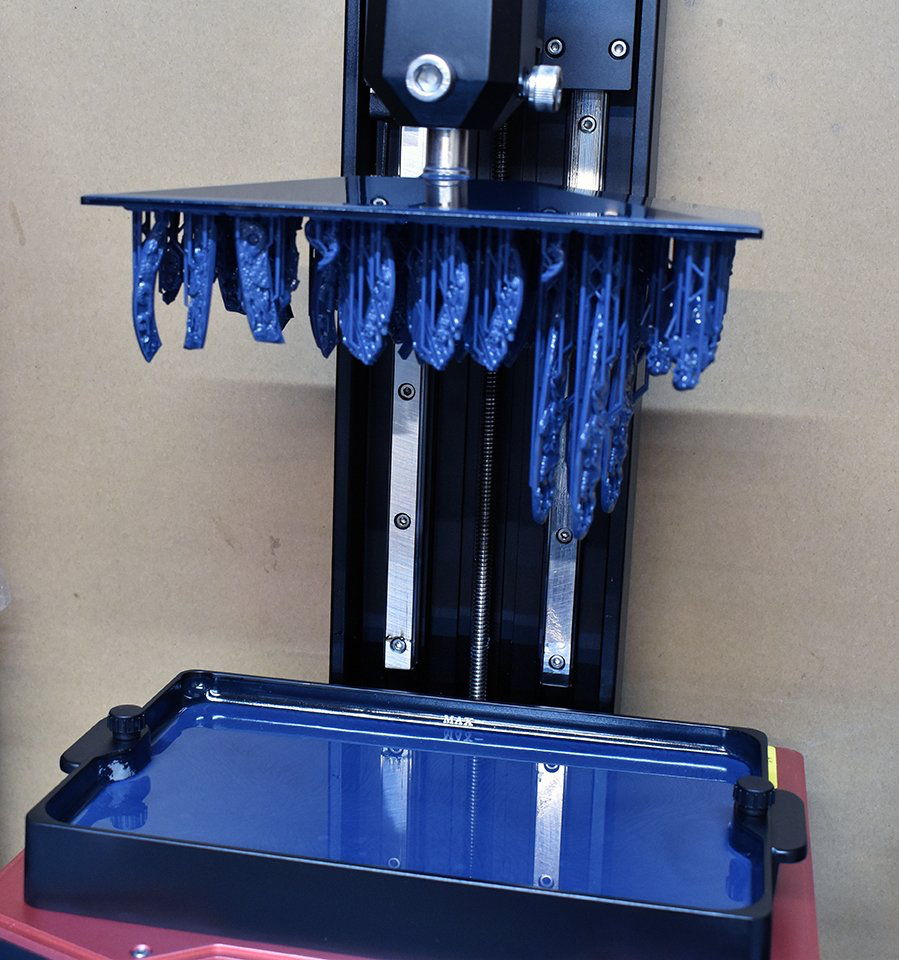
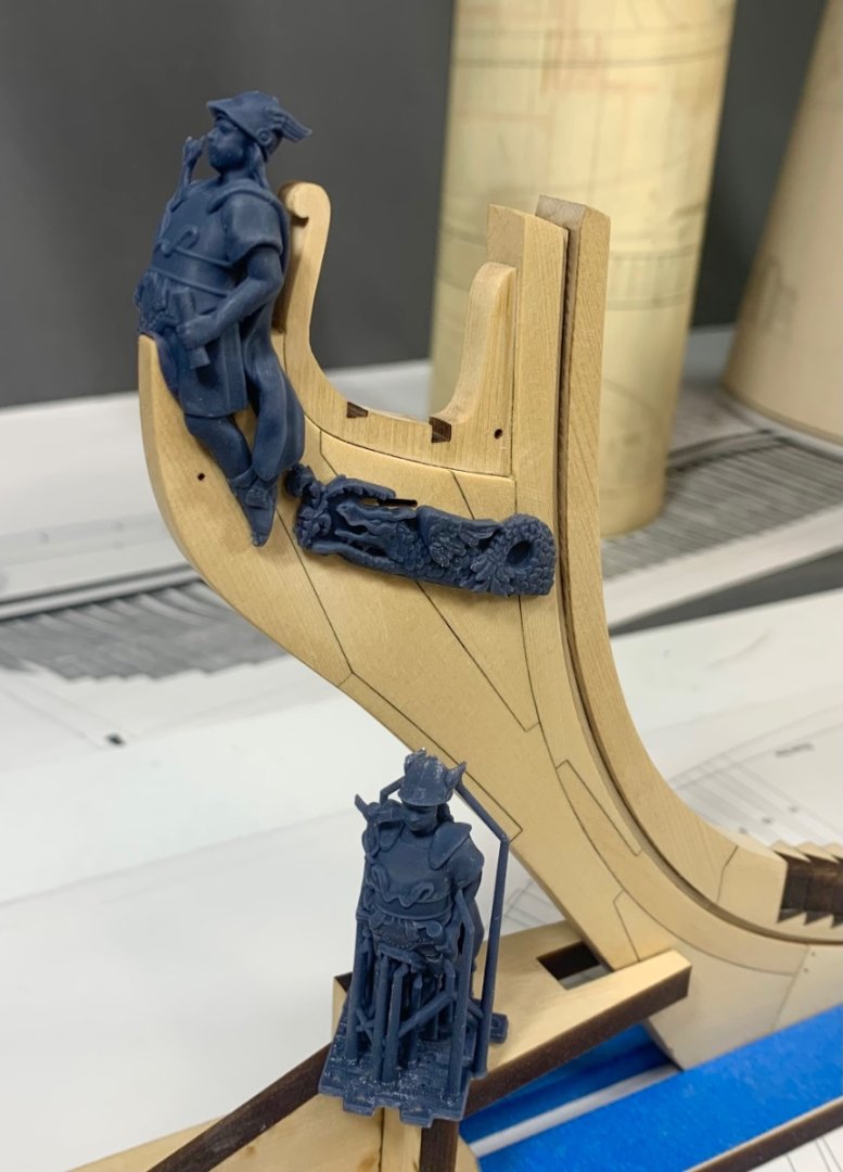
Its a new type of resin printer…you can get them for home use but as with everything else the ones worthwhile are expensive. I think Chris posted the i nfo on which one he got sometime ago. I literally am consciously trying to not learn another new technology…my brain cant absorb any more. CAD proficiency and new tech which is improving every couple of months. Its too much for me. So I will leave that aspect to others and gladly pay them what they deserve. It prints upside down….how cool is that. These are my parts being printed. When I get them I work on them extensively…sharpening and carving more details by hand. It may be hard to tell but just adding a few details with your own hand makes them look less polished and machine made. Then I use them as masters for traditional casting. I really should introduce even more evident hand carving but these are quite small. But I may still do more work on them.
-
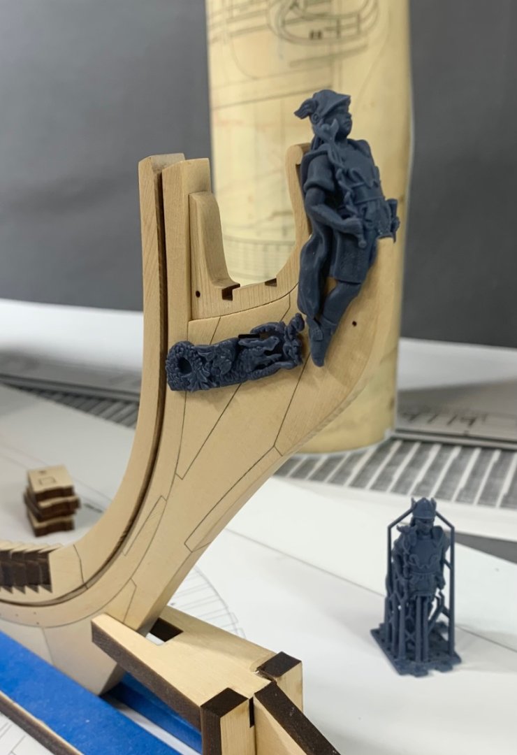
Did some work on the final iteration of the figurehead and trailboards today. The fit is really quite good. If you can imagine the hairbrackets in position…all will fit rather smashingly. Also picture them with a wood finish. With these done I can send the masters for casting in wood colored resin. Note the raw 3d printed example in the photos. Looks very Syfy like before the supports are removed and the figure is cleaned up and tweaked. Its all very interesting the way its done and printed with a high end resin printer. The surface quality is excellent. A big thank you to Chris W. from Vanguard for his help with these. so now its back to frame-making…
-
A really good start. Have fun with the project.
- 131 replies
-
- 2
-
-
- Medway Longboat
- Syren Ship Model Company
- (and 1 more)
-
We are here if you need us!!! Post more frequent updates of less progress and I am sure it will be easier for us to fore-warn you of future issues. We have all been there so its something the group routinely does for other participants. Just remember to have fun with it.
-
Ask the question before you proceed.....That is my only suggestion.... Its all here and a wealth of info and experience from participants who are well ahead of you. Take advantage of the fact that this is a group project. Its a wonderful thing. Chuck
-
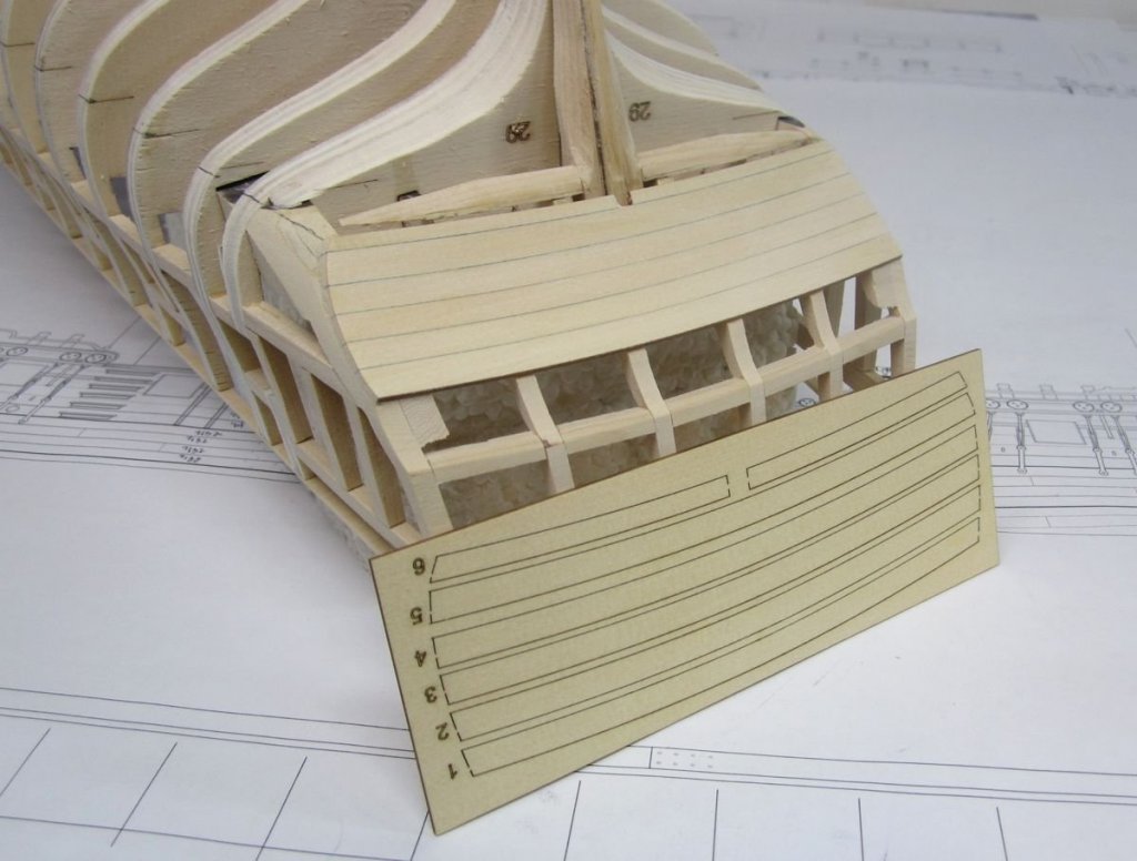
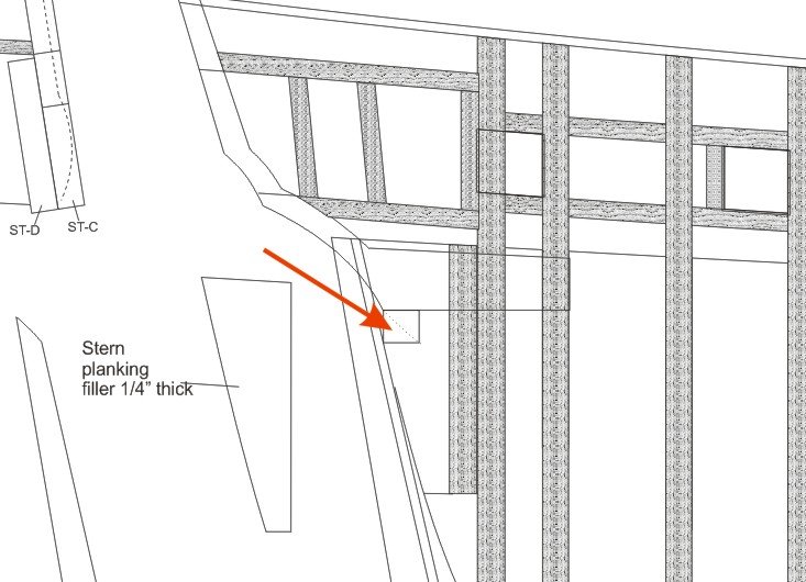
Its in there....take a look at that chapter again. Also mentioned in the instructions is another filler piece I recommend you place along the stern post that is faired to the hull shape. Its all in there so take a bit more time to examine the images and instructions. Adding that length of faired strip along the sternpost and glued to the bulkhead former will save you a lot grief later when planking. Should you recognize something that doesnt seem right or is missing I can only strongly urge you to ask those questions in your log before moving forward There are probably a dozen or so group participants that would be able to direct you to the info and post many images like those below. They are readily available. I would suggest trying to correct any twist on that stern before moving further ahead. That will only get harder to rectify as more planking is completed. Have you tried more "L" brackets against the former at the stern to force the stern transom into alignment? Perhaps just one on the Starboard side to force your transom a bit to port....after planking it should stay there. Chuck
-
A 3D model is indeed a model and worthy of being placed in the gallery. But the same rules apply. It must only be images of the completed 3d model. All others will be discarded. We dont have enough of them to warrant its own category yet but that is a new type of hobby modelling. Just as valid as wood or plastic. If you set up your album as public so anyone can post in it then it is likely other members who dont know what they are doing will be able to select it and add photos. It could happen. Just notify a moderator and we will delete them. In addition, we still have folks just adding photos in the gallery to the wrong category or not within an album. These are routinely discarded as well. You must create an album for each finished model. Then add your images to that. Chuck
-
Triton by Jerzy
Chuck replied to Jerzy's topic in HMS Triton - 28 gun frigate's Cross Section Build Logs for HMS TRITON
Yes for english ships like Triton treenails are on the outside. Straight through but for a model its easier to fake it and put them in from outboard only if you are going to plank inboard and not see them anyway.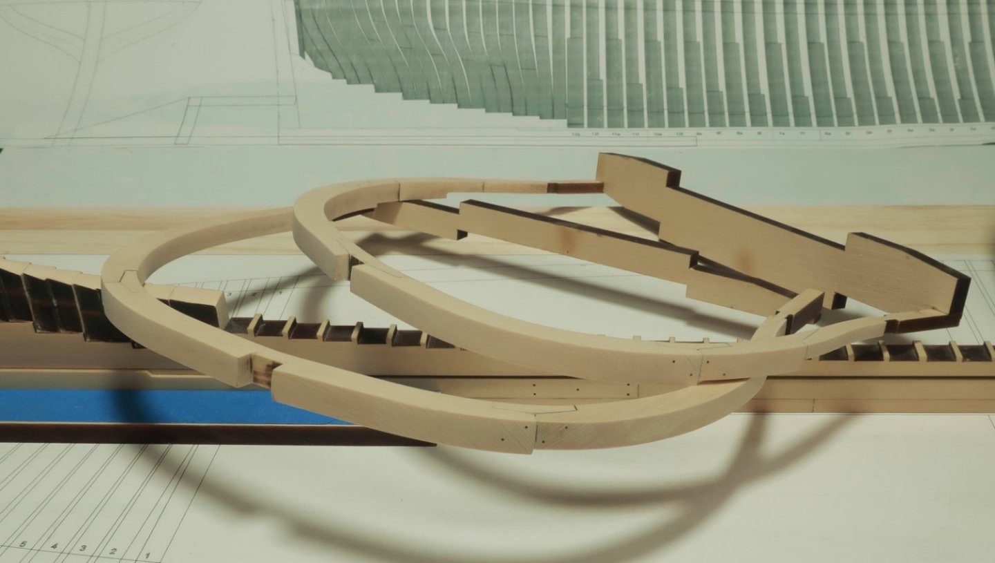
-
Triton by Jerzy
Chuck replied to Jerzy's topic in HMS Triton - 28 gun frigate's Cross Section Build Logs for HMS TRITON
Very nice Jerzy and it is so great to have you back building models. Looking forward to following your progress. Chuck -
Philip Reed's Speedwell
-
Beautiful…getting close to the finish line now.
-
Beautiful Mike…and hard to believe done with laser cut kit parts. I am pretty sure you wont find many other kits with headrails like that. you are in the home stretch now. The top gratings should be a piece of cake by comparison.
- 607 replies
-
- 6
-
-
- winchelsea
- Syren Ship Model Company
- (and 1 more)
-
Beautifully done.
-
Gutterman Mara color 682......get the size 120 or even smaller if you can find it. Which would be 150 0r even 200.
- 155 replies
-
- 1
-
-
- Medway Longboat
- Syren Ship Model Company
- (and 1 more)
-
Very nice work. Onward and upward as they say.
-
Thank You guys. I am not sure really. I dont find it any more difficult than building the Winnie. There are just more parts to put together. Once the parts are laser cut for you its really just an assembly job. Lots of laser char to remove....lots of frame parts. It just takes a longer time. You must really work hard at keeping everything aligned. Even with the jig pieces you still have to be vigilant about using that string to center your frames and your squares to raise them vertical. Fairing the hull is more time consuming as well. More time but not at all more difficult in my opinion. There are builders out there that always seem to to rush through things....not remove laser char etc. They will run into problems. If you have patience and can work slowly with care, it is not very hard at all. Like Greg said, even with the laser cut parts, maybe you can complete two or three frames a day. Its not hard but it does take a tad bit longer than assembling bulkheads. The Winnie was an exercise in planking....This will be an exercise in framing but you will save so much time later with Speedwell because you will only be planking from the wales up!!! Its a trade off.
-
Thank You guys...and happy New year
-
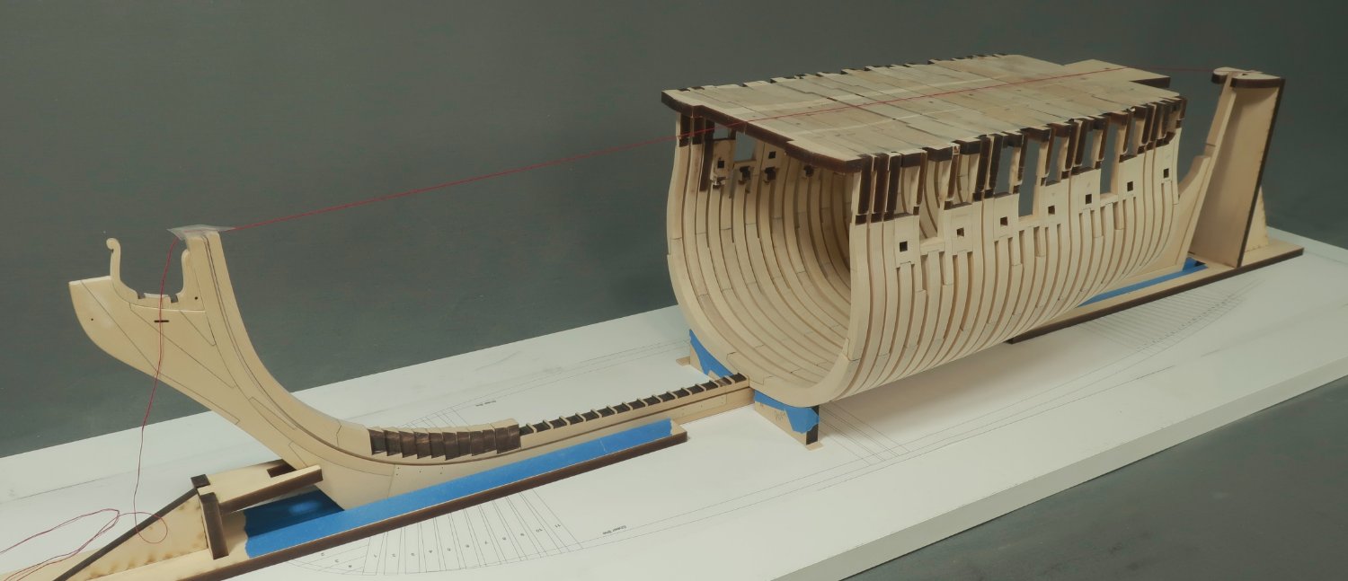
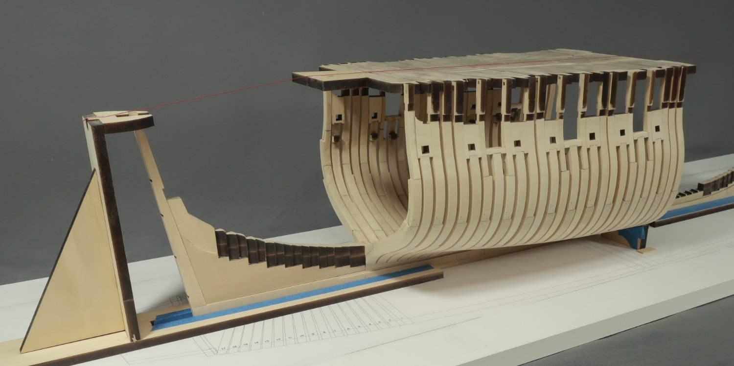
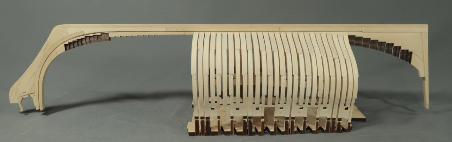
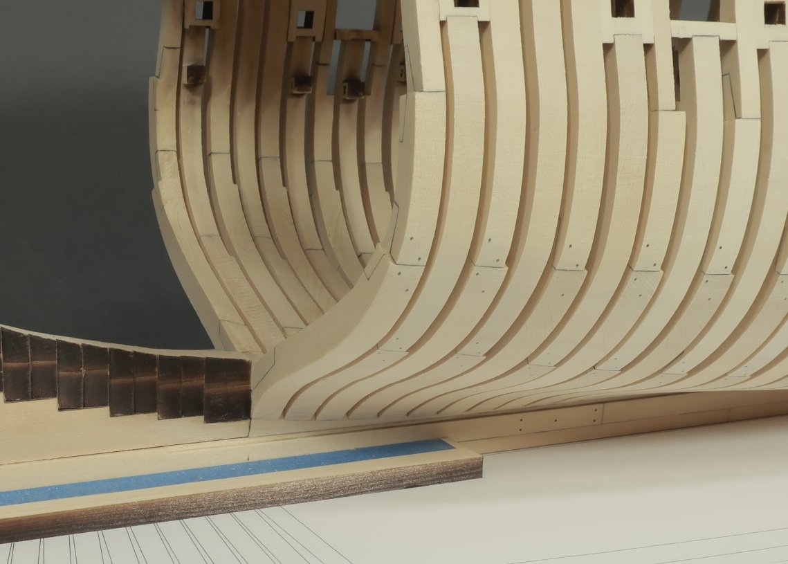
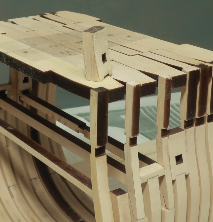
Work continues on the square frames. I thought I would post an update. I worked my way aft and have all of those completed. I am about two thirds completed with the square frames. Its all been uneventful. But here are a few pictures and some notes for folks who will be building her in the future. It is so nice to be able to remove the model with this "jigged concept". The cross bars that space the frames properly create a fantastic base so you can flip the hull over and do some progressive fairing. I designed it so the stem and stern post will be in the clear when its flipped. Its nice and sturdy to fair the hull. The build board I was using cupped terribly so I had to make a new one. It is important to have a perfectly flat build board. This is a pressboard shelf that has white laminate on it. It was perfectly flat and sturdy. We shall see. I also decided when I made the new build board to swap the aft support for a taller one. This is the support that holds the stempost straight up and vertical and centered. There was nothing wrong with the shorter one but I had a thought to make raising the frames even easier. I glued a string to the top of the taller stern post support. Then I ran it down to the center of the stem post and secured it in the center with some tape. This will be a great reference for finding the center down the length of the hull. I laser etched an arrow down the center of the top jig cross pieces....it always faces forward. But because its in the center, you can use the string to help you position each frame properly. They must be centered port to starboard....this makes it very easy to do when you raise each square frame on the keel. One thing I wanted to point out are the small wedges or "cradle parts" under the first square frame in the photo above. Once I had about six frames all done, these laser cut pieces were placed under the frame on both sides for extra support. They are laser cut to be a perfect fit under the center frames. They will be included in the kit as well. In addition, you might notice that those cross pieces for each shorter frame are no longer needed once you have the sweep port and gun port parts glued on top of them. The frames are grouped together and glued pretty solid. You can see them in the earlier photo. So they can be removed once you have those sweep port and gun port pieces glued in. This will give you access to the inboard frames....well somewhat. But I did do some progressive fairing of these frames inboard and out. Outboard was easy enough. Inboard is always a challenge. But you can see that I have at least got the heavy stuff off inboard. I use various chisels and my #11 blade to slice off the heavy stuff. A rough fairing....then switch to some rifler files. Then I switch to sandpaper. It is best to get a start on this because it will be a real chore if you dont at least get the heavy stuff off. I do this after every 5 or 6 square frames are raised. Out board was easier but the same tools were used. You can really start to see her lines start forming and the nice elegant shape into the stern....remember that the hull will be planked on both sides from the wales up to the shear. Care is taken to line up the sweep ports and gun port sills. I use a height guage or my square to transfer the heights from the framing plan to the model. Here is a somewhat close up photo of the fairing into the rising wood. These are last several square frames before the cant frames are started. You can see how the rising wood was faired nicely into the run of the square frames. This will make more sense to you if you are building it...LOL. Anyway...that is the progress to date and I will now start on the forward section of square frames in the exact same manner. It is a real pleasure to build upright and without all of that boxed scaffolding I see on other kits.


-
That is looking really good. It really starts to come together in this chapter.