DONATION DRIVE - SUPPORT MSW - DO YOUR PART TO KEEP THIS GREAT FORUM GOING!
×


Chuck
-
Posts
9,687 -
Joined
-
Last visited
Content Type
Profiles
Forums
Gallery
Events
Everything posted by Chuck
-
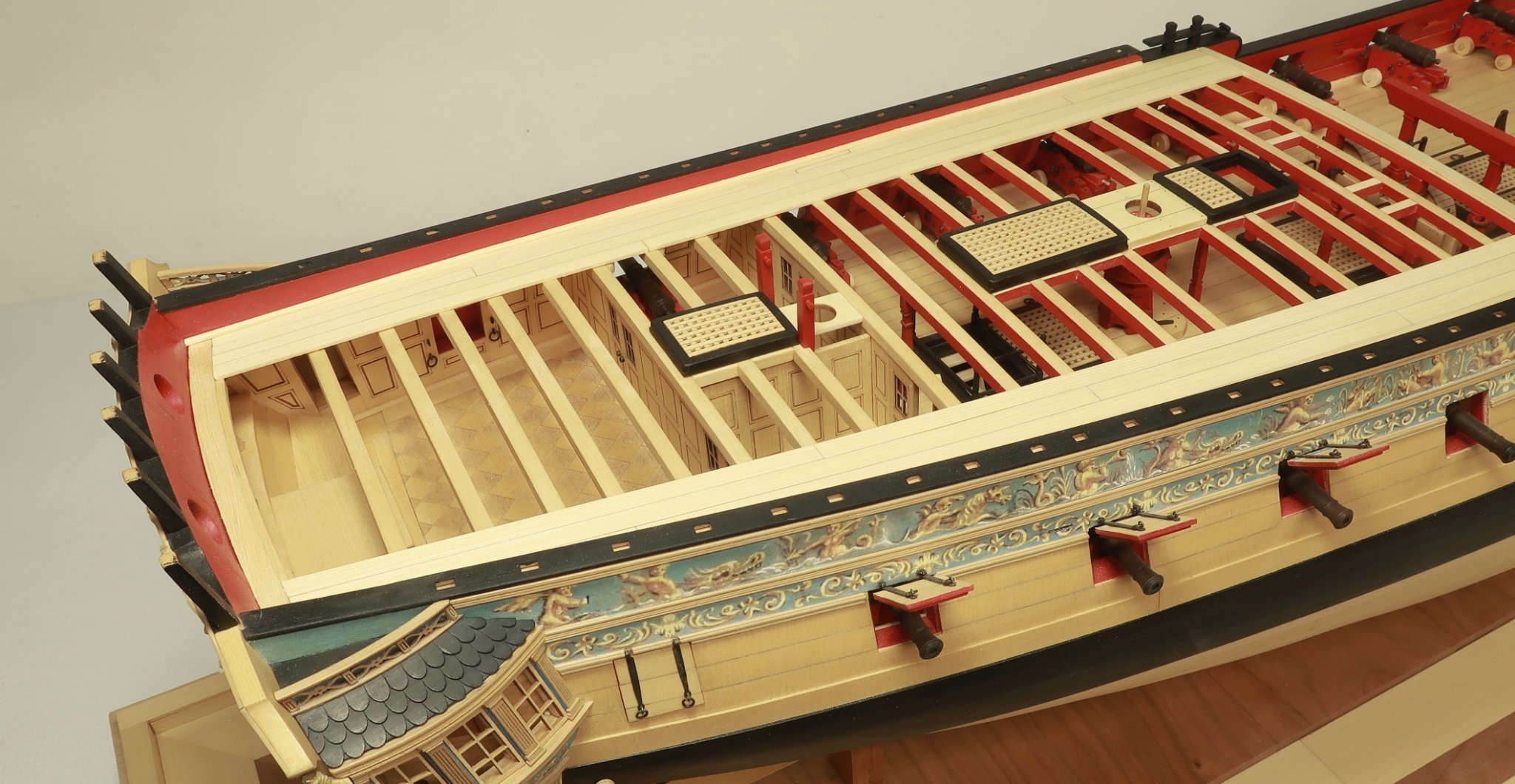
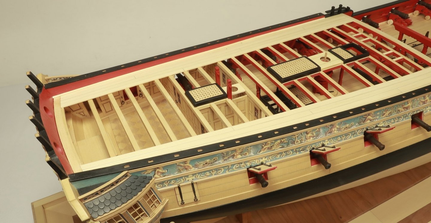
 I would think about omitting the pieces of the qgallery frame that sit against the transom and the hull. Why would you need it? Just use the front outside curved timber. Once the planking is added to the counter it should make it very strong. It certainly makes cutting it out easier and gives you more room inside gallery. Just a thought. Similar to this.
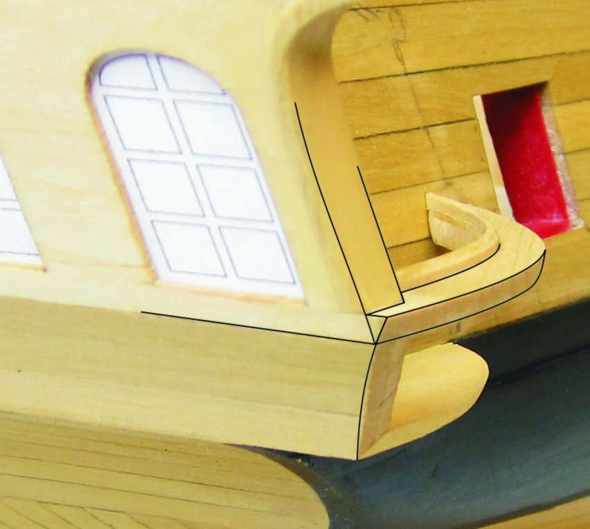
- 857 replies
-
- 12
-

-
- Sphinx
- Vanguard Models
- (and 1 more)
-
Materials List for Chapter 8 and 9. I am cutting chapter 9 parts as I write this!! Before anyone asks. Materials List for Winnie Eight.pdf Materials List for Winnie Nine.pdf
-
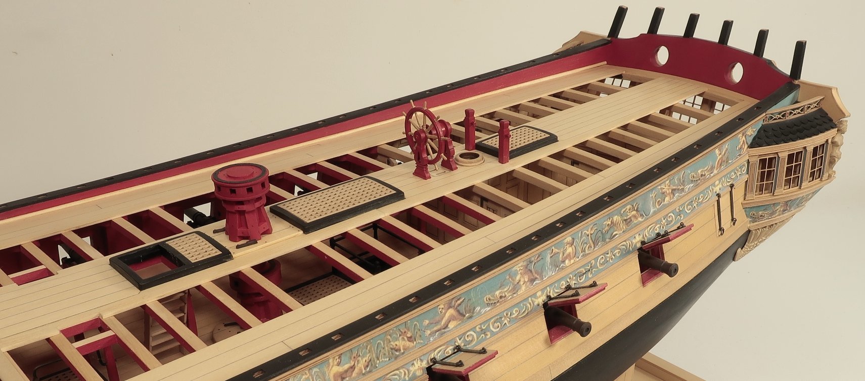
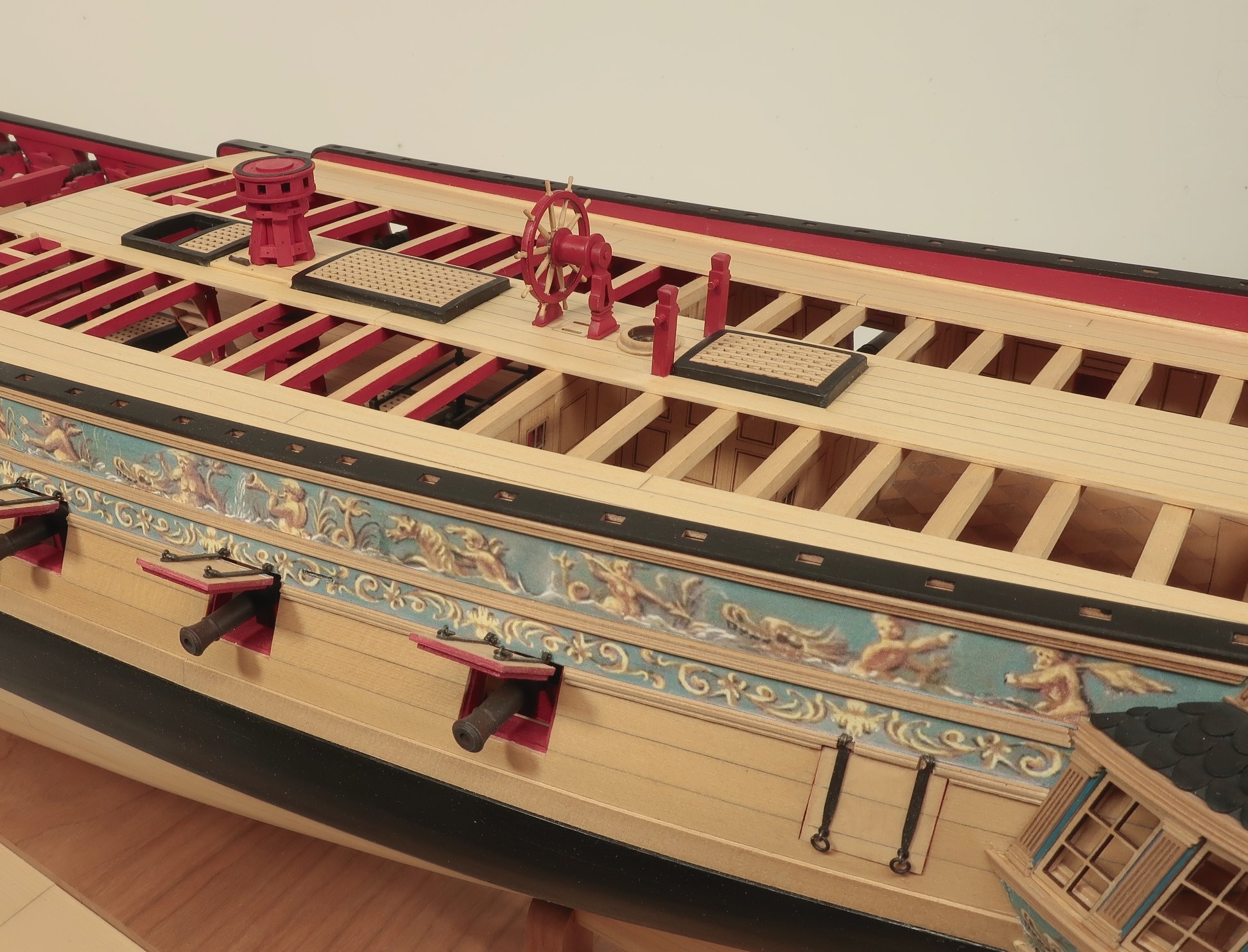
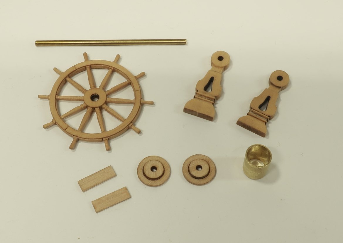
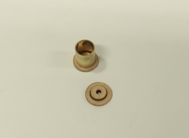
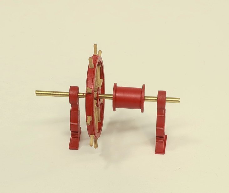
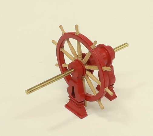
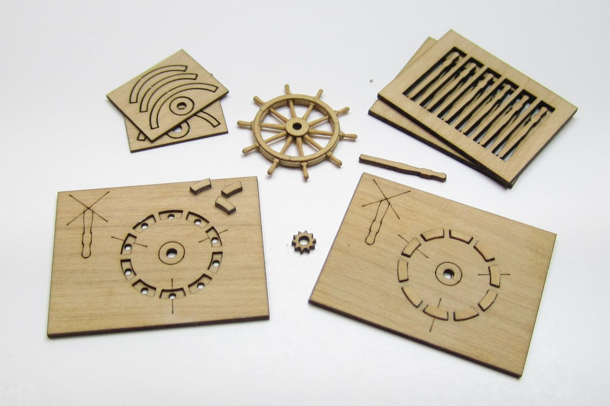
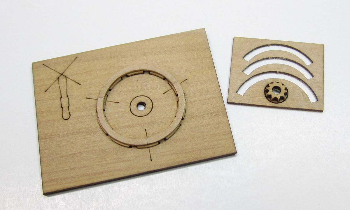
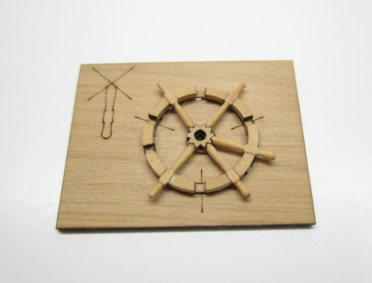
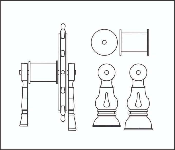
The 1 1/4" ship's wheel already exists as a mini kit as I mentioned. So I wont bother going through those instructions again. They are on my website as a download. But the other parts of the wheels assembly will be in the chapter parts. You can see the wheel and the other parts below. Note How the discs for the drum have two layers. You can glue the smaller disc to the larger ones as shown. The other parts had their char removed. The forward wheel support is longer than the aft support. This is done because of the camber of the deck forward to aft. So after cleaning the char dont glue the feet onto them yet. Those are the flat pieces or strips shown in the photo above. Once you test assemble all the parts on the 1/16" brass bar, you should position it on deck to see how it fits. Adjust the bottom of the two supports (probably the forward longer support) so the wheel is nice and vertical. You dont want it to lean forward because of the slope of the deck. Once you get those adjusted you can glue the feet into position. To complete the drum...take the 1/4" brass tube and it will fit onto the two layer disc. Then add the other side to finish it up. Paint it red. I also painted the supports red and the rim of the wheel. You can see in the photo below that the feet have been glued onto the bottom of the supports before painting them. Treat every fitting like it is a model all its own Treat every fitting as if it is the only project you have to work on….just smaller. As if it will be displayed on its own. Dont rush these. Cut the brass rod to length and glue the elements in position. Remember to face those supports in the right direction. The longer one on the forward end. Then you can glue it on the model. And the obligatory overall shot of the progress below. Next up will be the binnacle... Any questions? Or comments.


- 1,784 replies
-
- 33
-
-

-
- winchelsea
- Syren Ship Model Company
- (and 1 more)
-
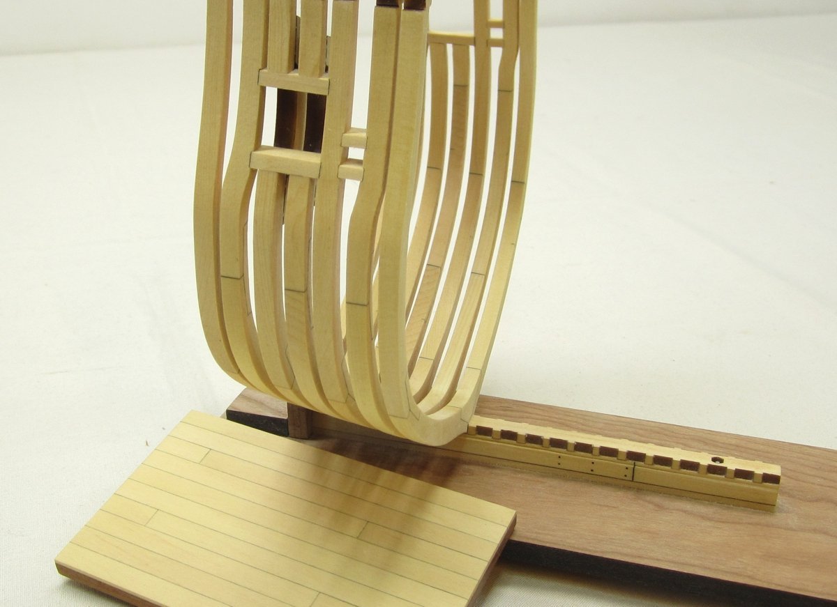
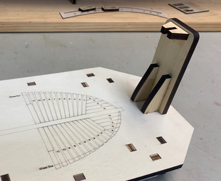
Well er about that.....The prospect another huge undertaking is a worry of mine. BUT, I may be taking the plunge into a Fully-Framed design for my next subject, whatever it will be. I think there needs to be some more choices for model builders rather than just those POF kits from the east that are emerging. If anybody wants to build a POF kit they are forced to only buy the stuff that comes out of China. So I may be the first to develop a full kit done in a style that is different from those being made in China at the moment. I think I can do better. We shall see how it goes over the next few months. I can tell you that tests are already underway. But its still 50-50 which way I will end up going. Not just a cross section either...but a full hull. You have seen my other tests into this type of POF development by now. There are more on the drawing table at the moment. I think I should do this only because I am not getting any younger, LOL. So I may as well get this out of my system before I get too old to consider it.
- 1,784 replies
-
- 31
-
-
-
- winchelsea
- Syren Ship Model Company
- (and 1 more)
-
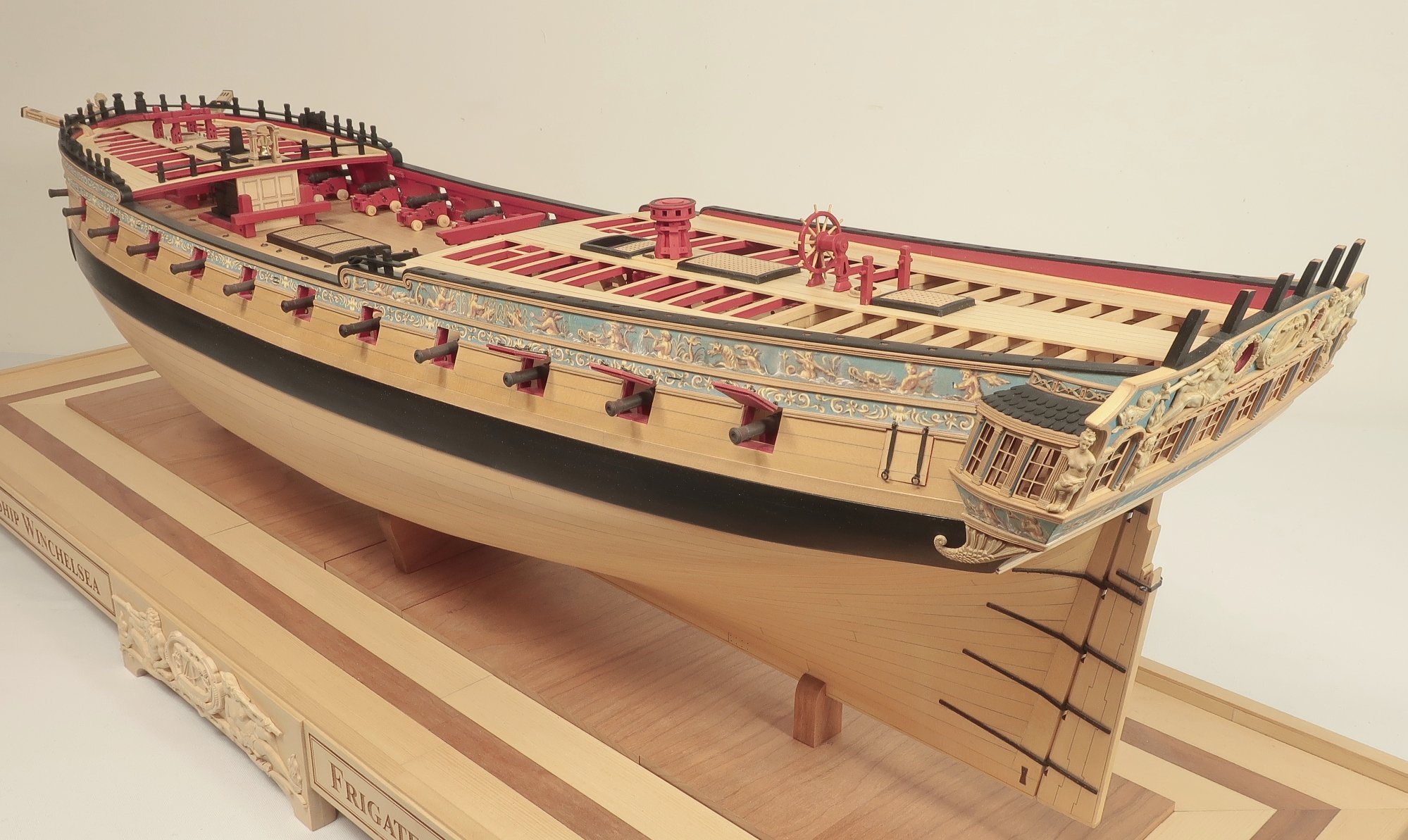
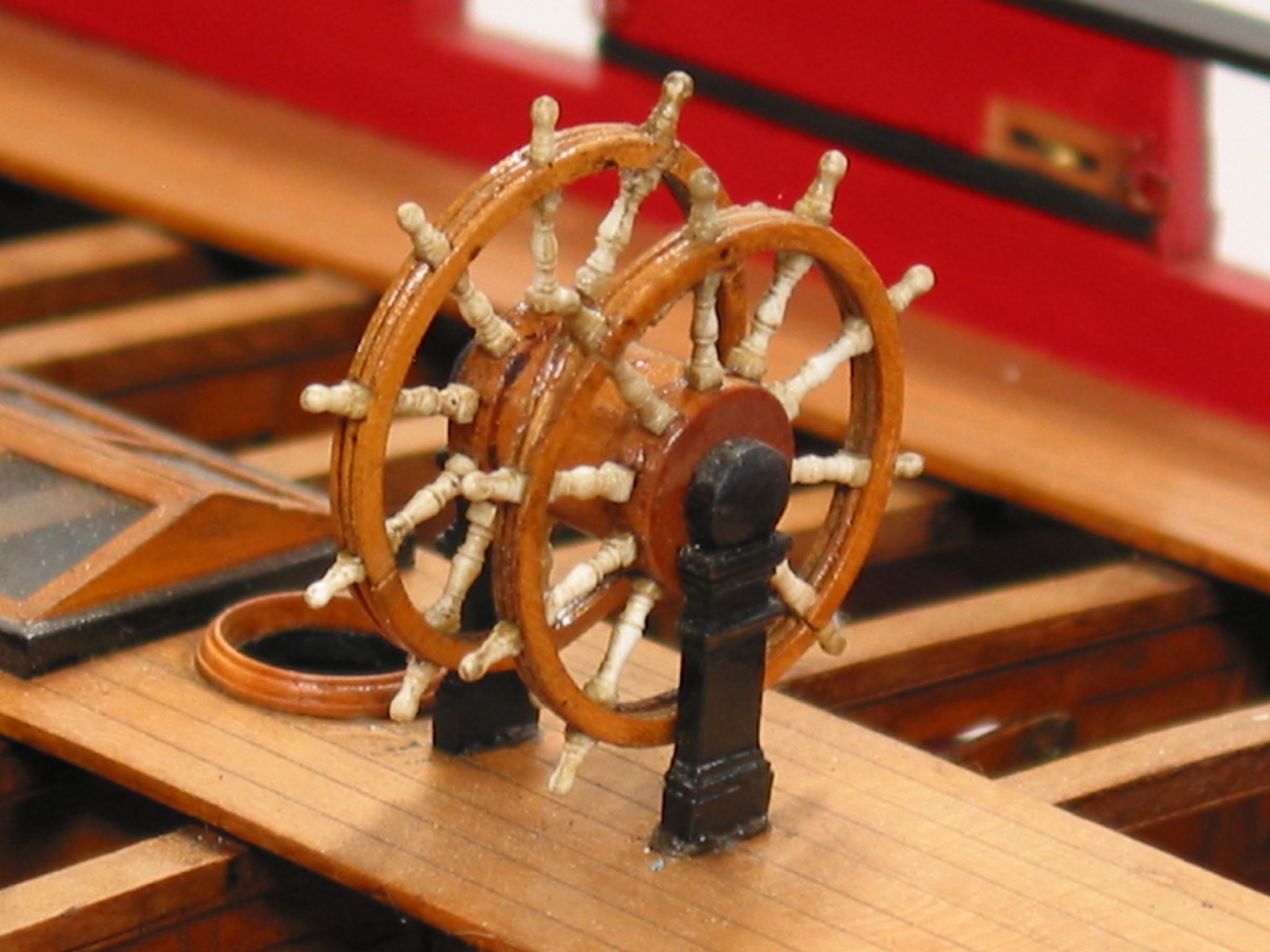
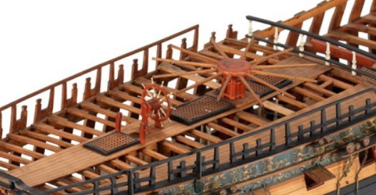
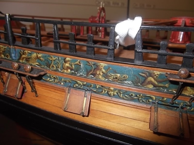
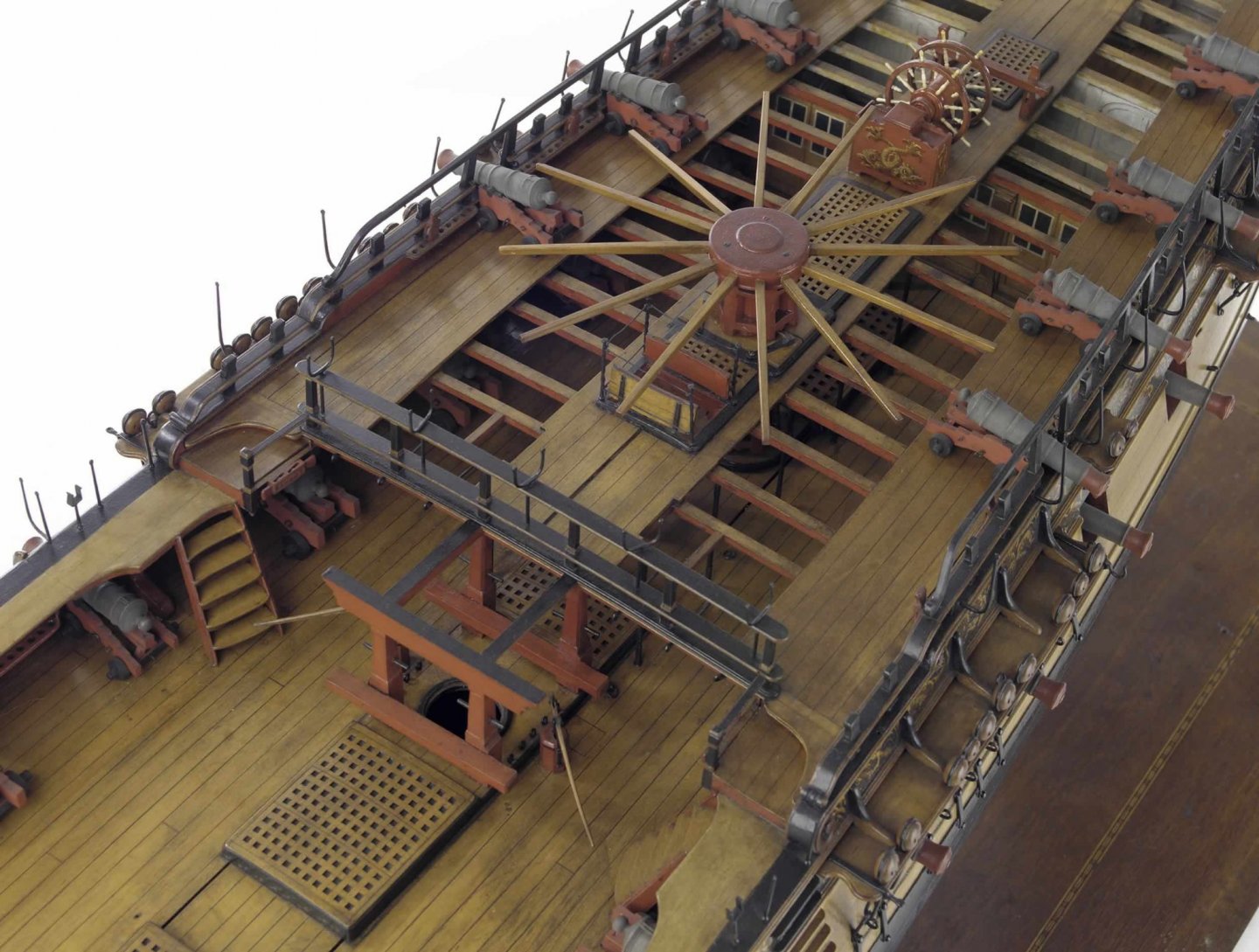
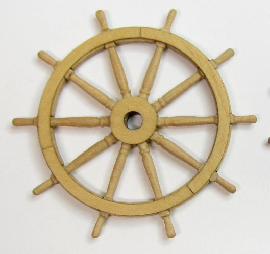
More paint color choices on the wheel as well. Here are some photos. For the contemp. model as you can see, the supports, drum and rim of the wheel are red. The spokes are ivory. I may be doing the same except leaving the spokes natural boxwood. and some winnie parts for the wheel being tested and contemplating color choices as well. This just taken with my Phone. For other cont. models its similar but there is some variation. Minerva...which has a double wheel. Winnie does not have a double wheel. But you can see how the supports are black in this case. And Amazon...all read with ivory spokes again. Again a double wheel. The ships wheel for the Winnie is sold separately and is already available. Sold one per package. For those guys waiting for the next chapter this is something that could be bought and made in advance. Its just the wheel as the other parts will be part of chapter 10. Buy the larger 1 1/4” wheel for Winnie. The wheel kit is built just like other master model builders build them. There are lots of small parts but it makes a beautiful boxwood wheel as you can see. You just need to go really slow and take your time. If you rush through the wheel mini kit …it will look a mess. So take your time and practice.

- 1,784 replies
-
- 30
-
-
-
- winchelsea
- Syren Ship Model Company
- (and 1 more)
-
Thank You.... Just a reference for next fitting.
- 1,784 replies
-
- 12
-
-
- winchelsea
- Syren Ship Model Company
- (and 1 more)
-
That is looking really good. Nice planking job. That will be a fabulous model.
- 857 replies
-
- 3
-

-
-
- Sphinx
- Vanguard Models
- (and 1 more)
-
Chapter 9 isnt out yet. I am working on it....The stove is chapter 8 and is already out. That has been out for a while. Chuck
-
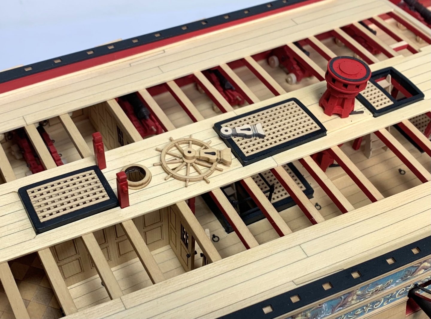
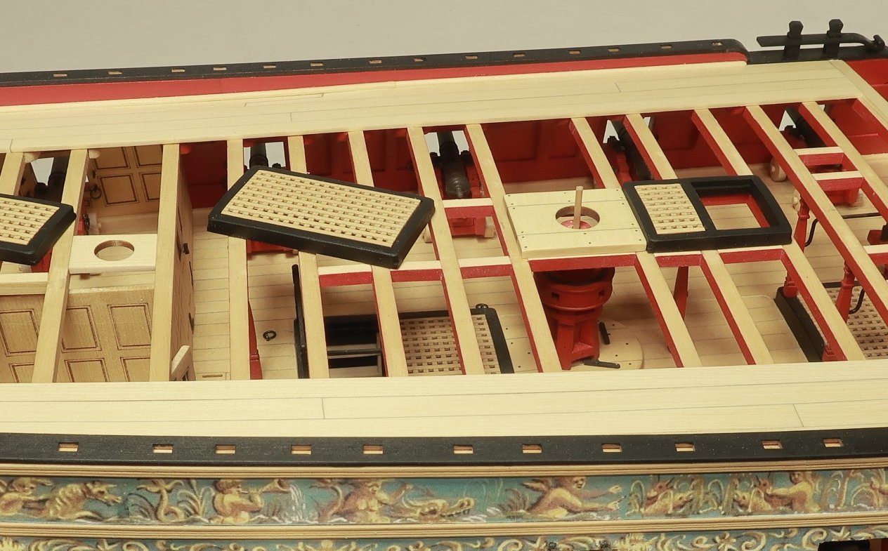
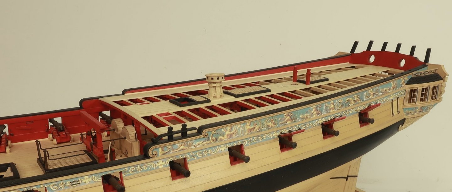
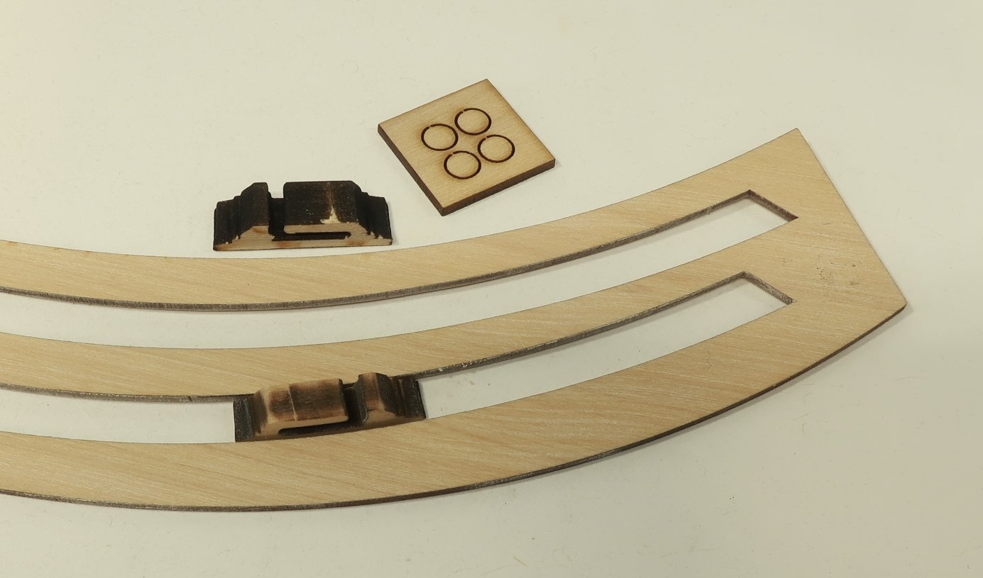
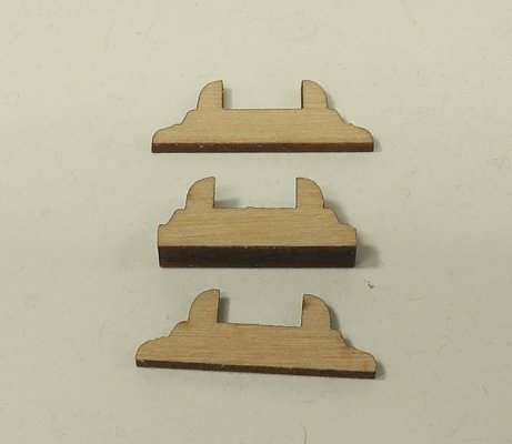
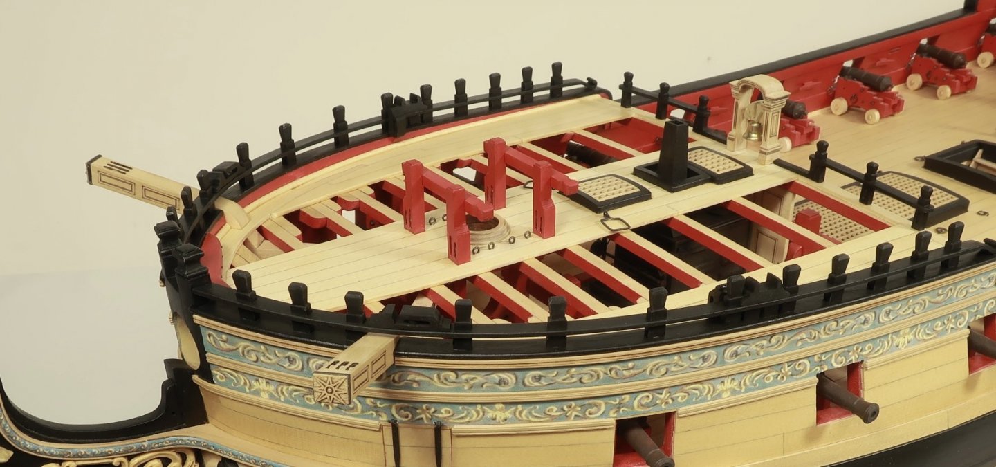
Thank You for posting. Today chapter ten was started. You saw that I had already planked the qdeck along the bulwarks after adding the margin planks. So before I could plank down the center I had to get the coamings all made. The coamings are build exactly like the others we built. They are laser cut for you. Just build them using the 3/64" thick right angle template as before. Round off the corners......yada....yada....and add the cambered gratings. Two packages were enough to do these three. But dont glue all three down yet. Only glue the forward most grating and coaming in first. This is very important. As you can see above, the first coaming was positioned and then it could be used to help position the capstan partners. These are also laser cut for you. But because so much depends on where you placed you beams.....where you placed your lower capstan, etc.... I laser cut the three parts for the capstan partners a bit longer on both ends (forward and aft). This will allow you to adjust to suit you model and get the round opening directly centered over the lower capstan. Then trim the aft side so it falls on the deck beam nicely. The aft end of the partners should cover half the beam it sits on. Then the other coamings can be glued in position. Make sure to center them down the qdeck of course. In that same photo above you can also see the mizzen bitts. These must be glued to the forward side of the beam before you start planking. So these were made up next. They are laser cut but you must finish the top timberhead shape as is usually the case. There is a hole laser cut through these as well. They will accept a 1/16 dia. rod. Use either brass, or even styrene or wood. It doesnt matter. You will have to clean out the holes with a 1/16" drill bit first as the laser doesnt cut a perfect right angle. So I made this hole slightly smaller as a pilot hole. Drill them again with a 1/16" bitt and insert the rod. Use the plans to get their length. Above you can see the bitts pretty good. But you can also see a modeler's convention for adding the slots for the ships wheel rigging. This is laser cut in two layers 3/64" thick. The lower layer is glued between the deck beams first. It has a laser etched reference for the second final layer. Just glue it on top like in the photo. We will plank around this. Finally the planking can commence down the center of the qdeck. Use your template as a guide like when you planked the fcastle. This will complete the planking or most of it. We still have the gangways to do but that will be done much later. You can see I also test fit the upper capstan. I still have to paint it red and add the metal band. But its all coming together. That will be done next along with the pawls....and also the mizzen mast coat. With each update she is getting less naked. Its is starting to fill out nicely with details. Any questions. On the workbench…
- 1,784 replies
-
- 36
-
-
-
- winchelsea
- Syren Ship Model Company
- (and 1 more)
-
Looks very good to me. Slow and steady.
- 642 replies
-
- 1
-
-
- winchelsea
- Syren Ship Model Company
- (and 1 more)
-
Looking great Rusty....onto the fun stuff....
- 642 replies
-
- 1
-
-
- winchelsea
- Syren Ship Model Company
- (and 1 more)
-
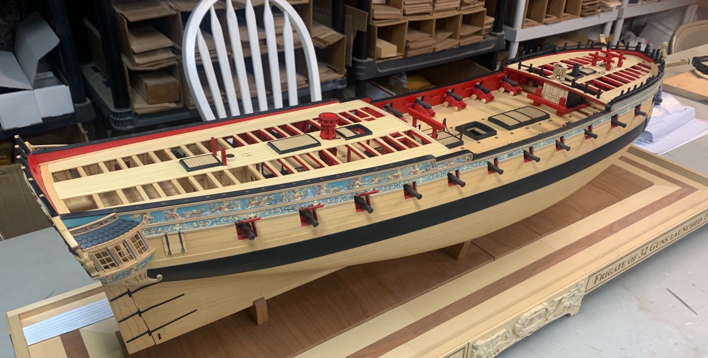
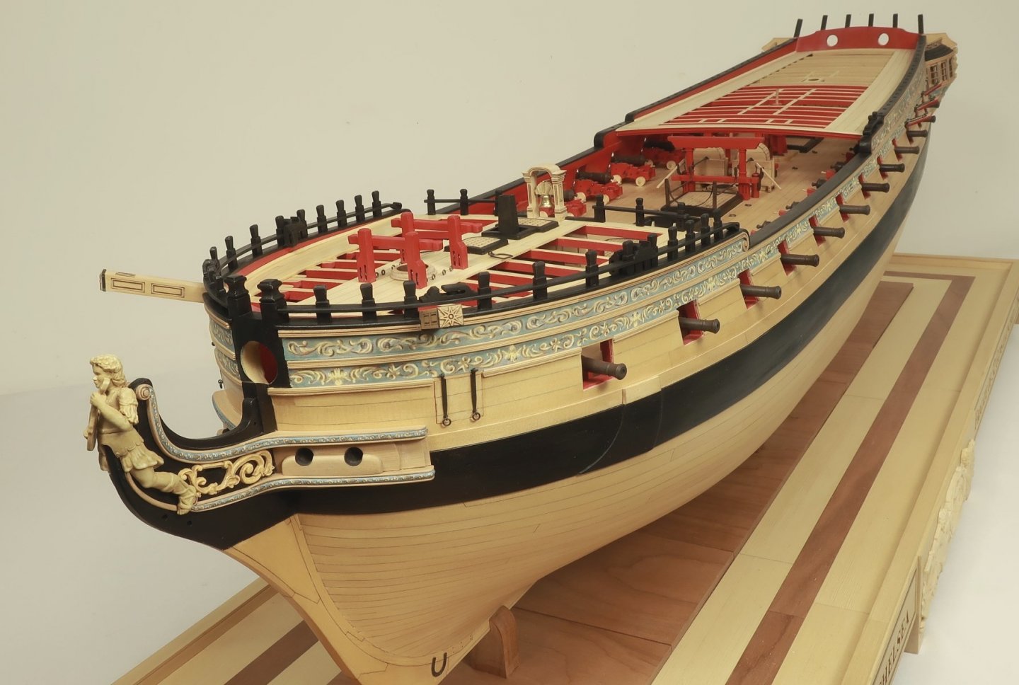
I finished up the fcastle rail on the starboard side. That left only a few fittings to make which are all added to the fcastle rail. These include the spanshackle cleat. This is made in three laser cut layers. It will be painted black and positioned on the rail following the plans. Under this cleat are two posts to help support the rail. There is also the "cat block" . This is laser cut and is 1/4" wide. But you will need to sand a curve into it that matches the curve of the rail. If you saved the laser cut sheet for the rail this is perfect for tracing the shape. Then sand it carefully to match. Insert the small sheave and paint it black. The last remaining fitting is another sheave as part of cleat....I am having a brain fart and recall its name currently. It is positioned along the bulwarks on the inboard side of the spanshackle cleat. This has been laser cut also and all you need to do is add the small sheave disc. Then paint it black...but below the caprail it should be painted red. You can see it in the photos below. In addition I have added all the eyebolts and the spanshackles. The spanshackles are made from 22 gauge SQUARE wire. If you cant find any square wire you can use regular 22 gauge wire. Use the plans to find the locations for the eyebolts and the size for the spanshackle. This pretty much finishes the fcastle details and chapter 9. The only thing I have yet to do is the cover boards for the stack opening. Those should be made out of any scrap 3/64" thick strips or sheet. This wont be laser cut because everyones stack will be positioned slightly different. Some overall pictures of the hull up to this point. Next I will start chapter 10 which is finishing up the qdeck details and rail.


- 1,784 replies
-
- 36
-
-
-
- winchelsea
- Syren Ship Model Company
- (and 1 more)
-
You should post another topic in the wood forum. You will no doubt get lots of tips from the usual suspects. Probably more info than you could ever want.
-
You might as well add the waterway as well. Dont forget that.
-
That small bend shouldnt be a big deal at all. But perhaps you should try and cut another if you are up to it. But if the next one bends like that I wouldnt worry about it too much.
-
Perfect.....well executed indeed. Chuck
-
2021 NRG CONFERENCE
Chuck replied to kurtvd19's topic in NAUTICAL RESEARCH GUILD - News & Information
Yes, it was announced….. just a few posts back in This topic actually. -
2021 NRG CONFERENCE
Chuck replied to kurtvd19's topic in NAUTICAL RESEARCH GUILD - News & Information
The 2021 conference was cancelled. Nobody will be attending this year. Looking forward to 2022 however. -
If you can find the black fishing line. Its cheap enough. Get a range of weights. I think 15lb might be a bit small for keel bolts. Probably 20 or even 25lb is more appropriate. I have a large stock of the stuff from 10lb all the way up to 60lb. The brand is Sunset Amnesia. https://www.ebay.com/itm/154155421343?epid=1412250970&hash=item23e4610e9f:g:zHkAAOSw5Z1fkaGO
-
Its not anything I can recommend. I use medium CA and that works for me. But it will be different for everyone. You should try all three and then pick the method that works best for you. Chuck
- 1,784 replies
-
- 6
-
-
- winchelsea
- Syren Ship Model Company
- (and 1 more)
-
That looks great. I dont see anything wrong with those at all. Beautiful work.
-
Great start.....Remember to have fun with the project. Thank You for starting a log. Chuck
-
Jim is correct in that those cross sections are made by Unicorn which is one of the largest pirate mfg’s in China. They have stolen designs from many others such as Amati, Panart, Mantua, Corel etc. And yes the Druid kits you mention are copies and knock-offs of Harold Hahn’s Druid plans although reduced. They are 1 to 1 copies actually. Their kits are not allowed on MSW. Purchasing them means giving monetary support to them. And yes they are cheap, as is typical of Chinese products.
-
Its coming along. A little tip...Its much easier to sand both faces of the parts BEFORE you remove them from the laser cut sheet. Its stays nice and flat and you can just run some 320 grit on both sides of the parts to clean them up perfectly. Especially if you wont be removing the char from the cut edges. You can even use a sanding block without worrying that you will round off the edges.
- 840 replies
-
- 9
-
-
- winchelsea
- Syren Ship Model Company
- (and 1 more)