HOLIDAY DONATION DRIVE - SUPPORT MSW - DO YOUR PART TO KEEP THIS GREAT FORUM GOING! (Only 75 donations so far out of 49,000 members - C'mon guys!)
×


michael mott
-
Posts
5,200 -
Joined
-
Last visited
Content Type
Profiles
Forums
Gallery
Events
Everything posted by michael mott
-
 Hi Steve nice solution, I remember when I was tackling thimbles I came up with a different way for making them, if you need a different size you could try this method as well. it is on page 11 of my cutter thread. Michael
 -
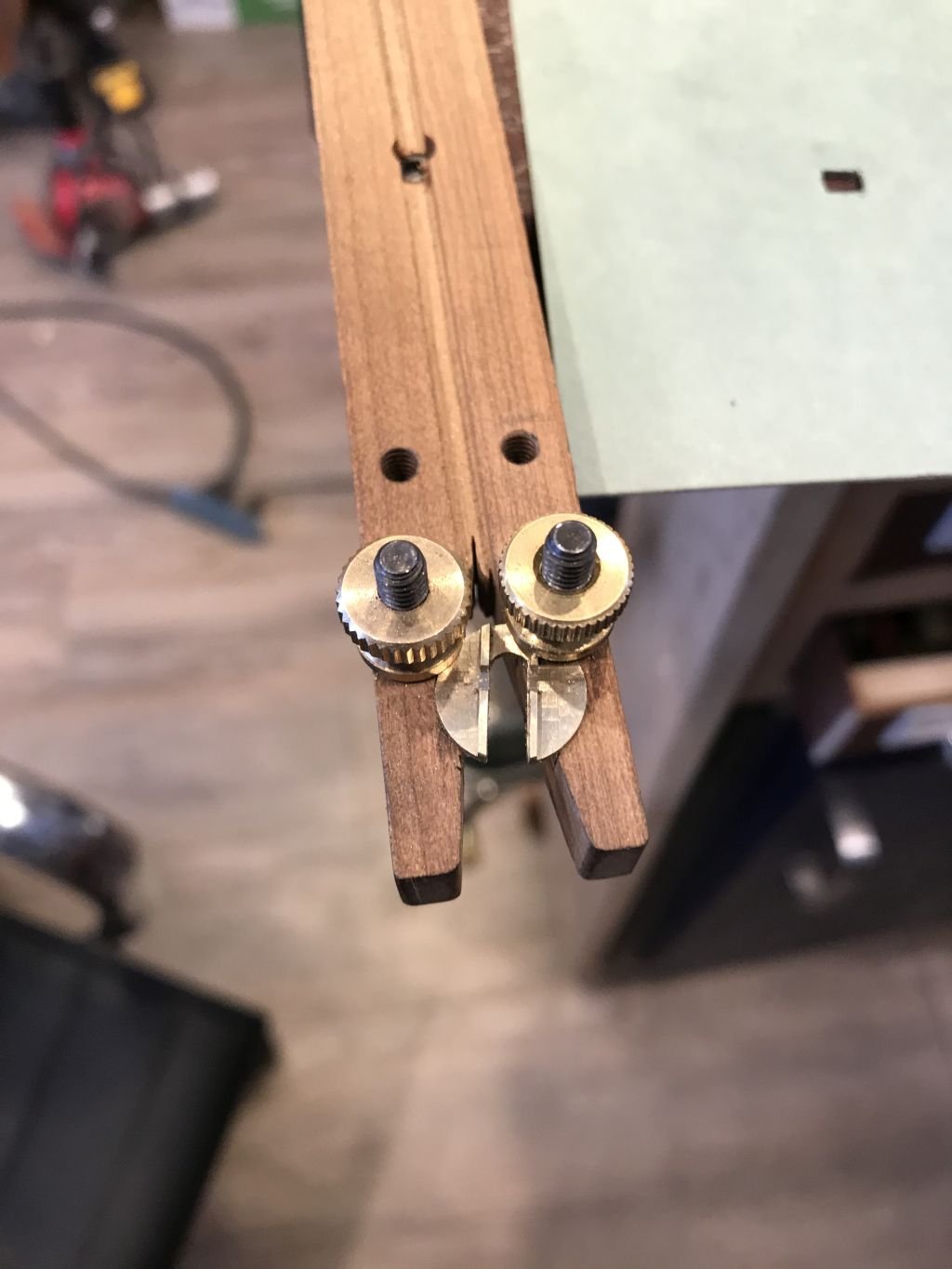
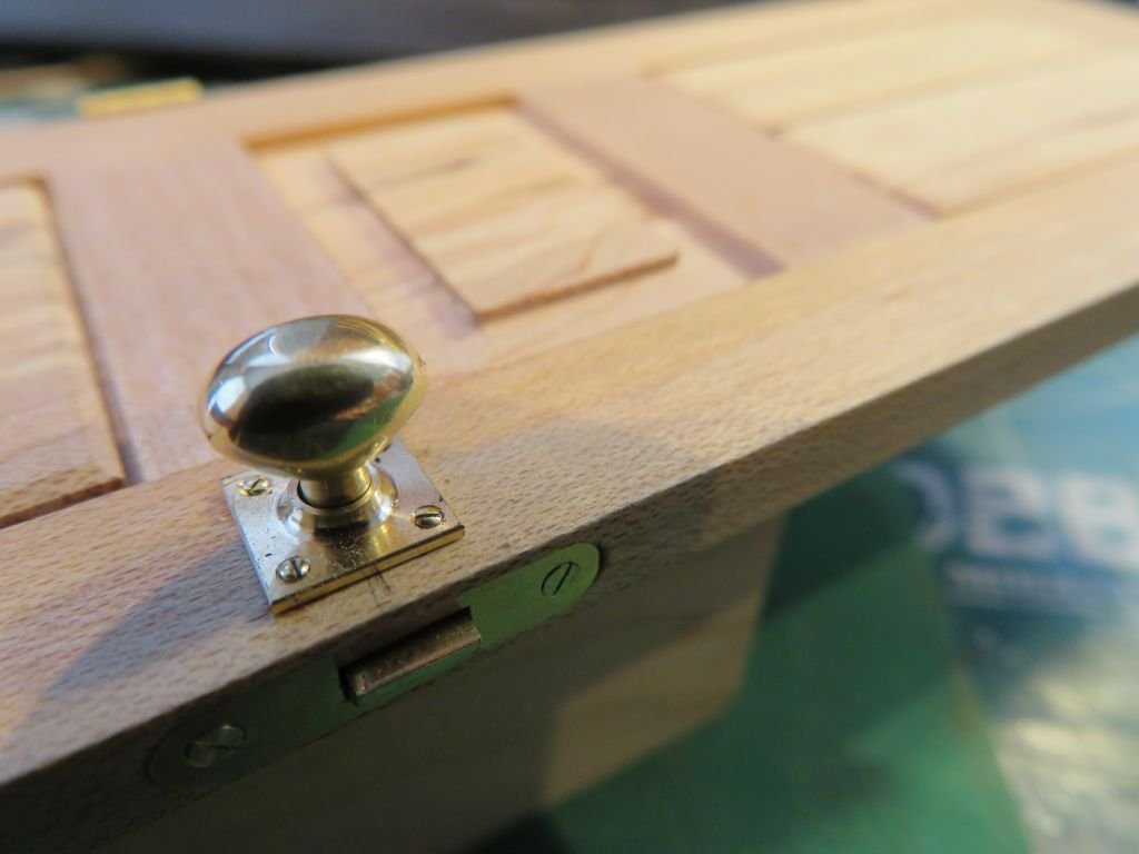
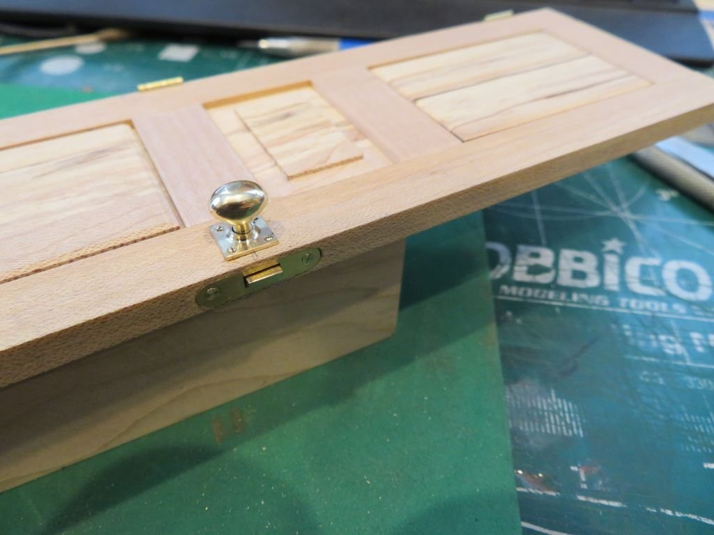
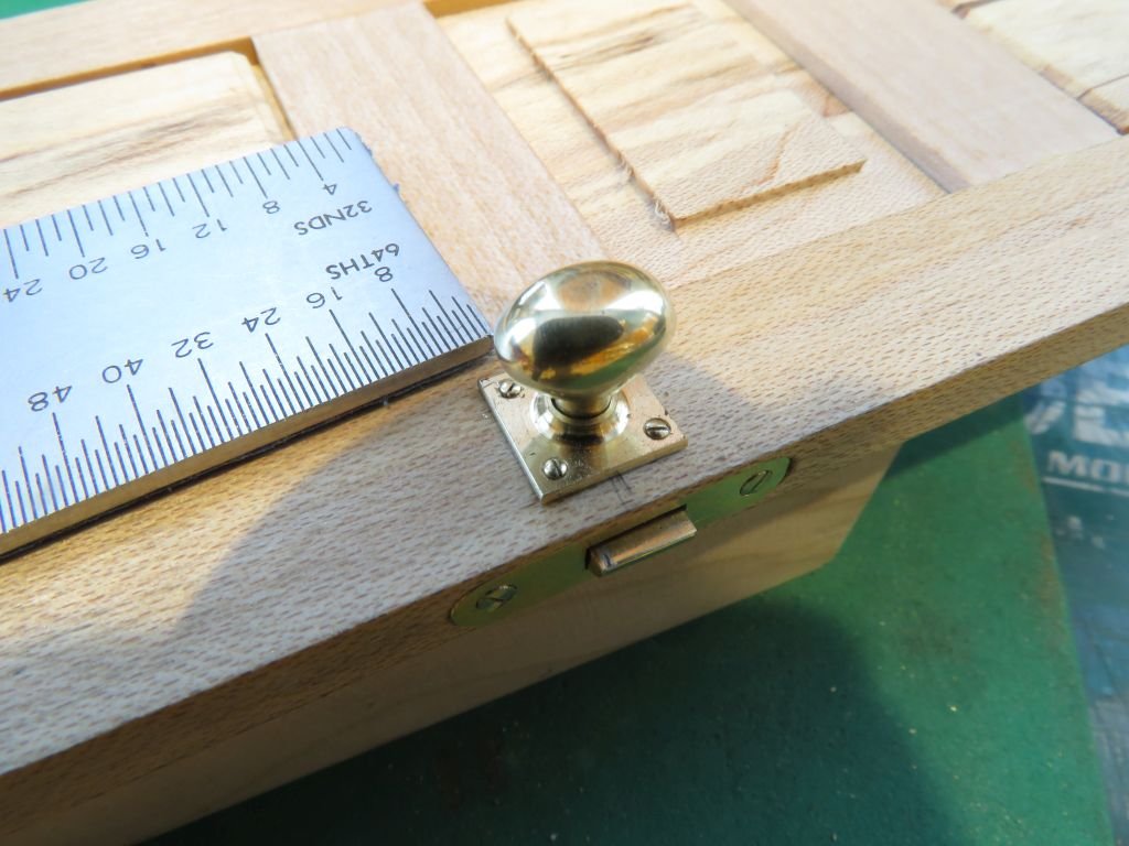
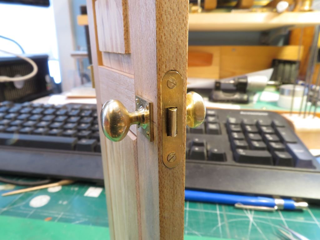
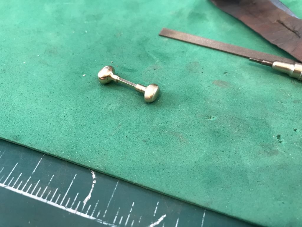
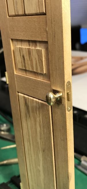
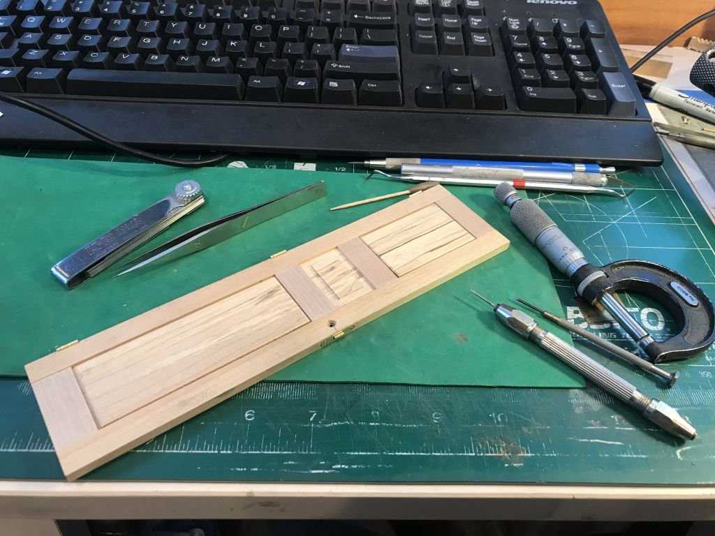
Greg, Druxey, Rick, Dirk, and Kurt, Thank you all for you kindness. I have just about finished the handles now, The second Handle require a slightly different approach because I needed to insert the square tube into it. and I needed to do that under pressure so a tight fit. first the rough shaping. Then after getting the handle shaped the square tube was pushed into the hole. Then cut off with the Jewelers saw. I used the watchmakers key tool as a holder for the final polishing. And the handles are done. Next the square roses were drilled and countersunk The fake screws are basically the same as the hinge screws except these are oval headed. and the back set mounted on the door as well, just four more screws. Time for a break today. Michael
-
Gary that winch is really impressive, clever solution for the cable on the drums. Michael
-
Grant just finished going through this build log, what a nice model. Also very impressed with you shop organization. Michael
-
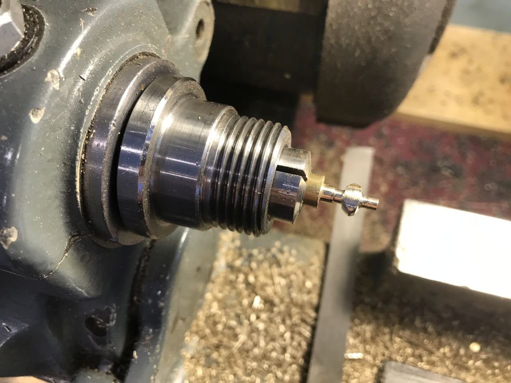
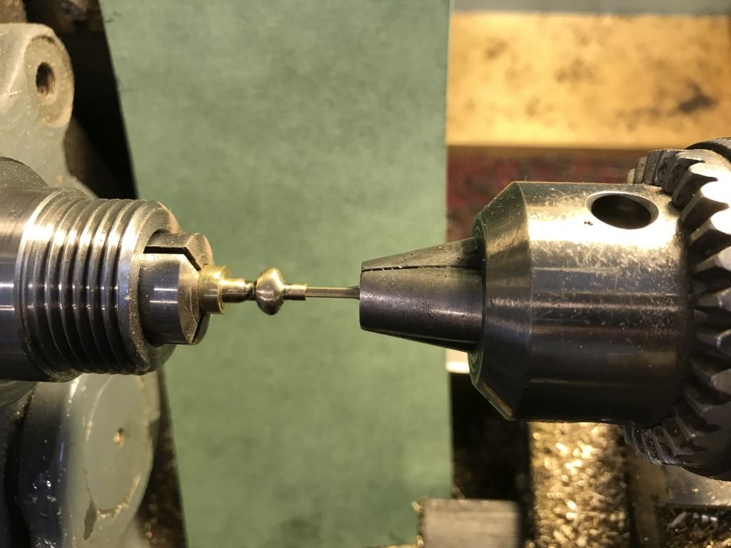
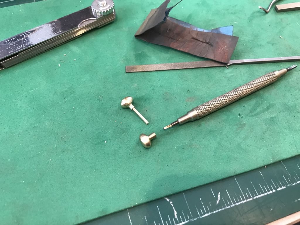
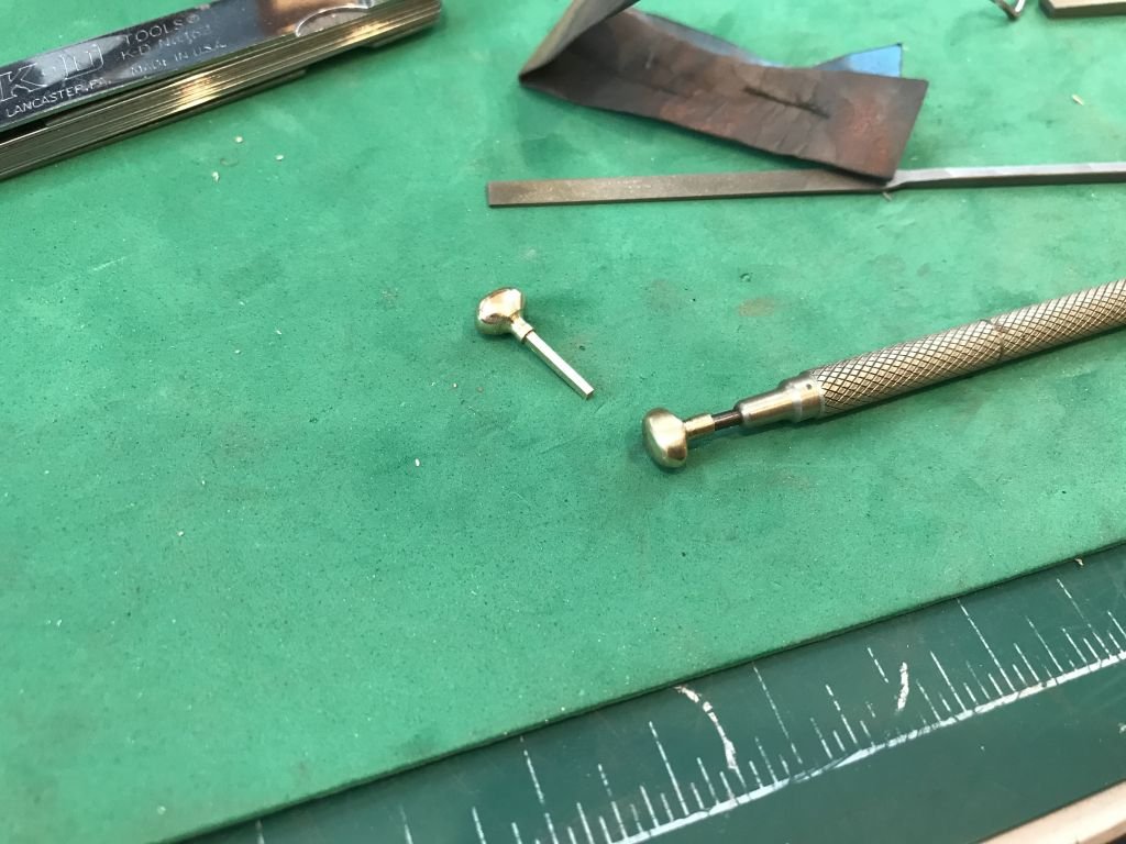
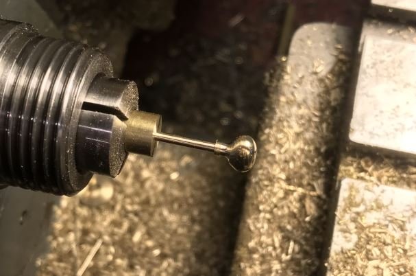
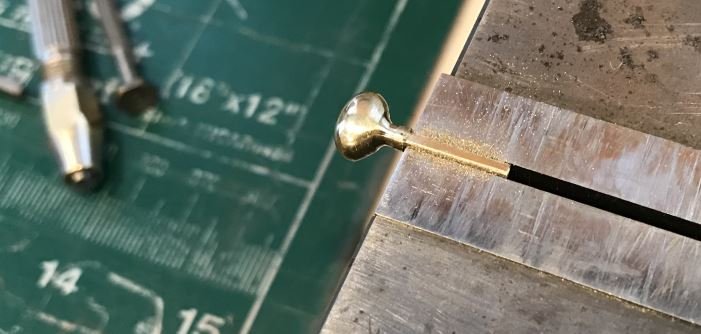
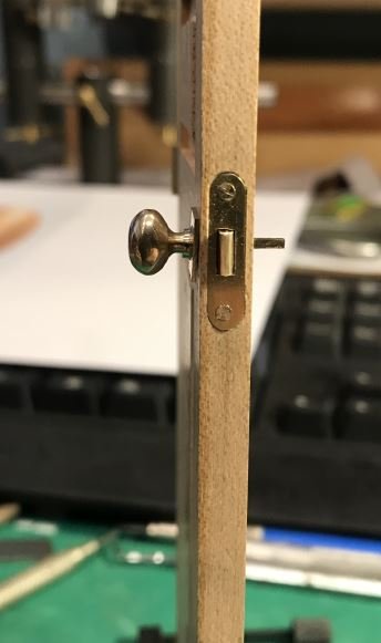
Thanks again for the kind remarks, I settled on the oval handle I found a classic one that was for sale on Ebay so used that one as a guide I liked the 2 inch square plate and the oval head screws. I set up the 1/2 inch collet in the square collet holder and made 4 cuts The parted them off on the lathe Next I turned up a ball and filed the sides to create the oval shape it took a bit of fettling to get the correct shape. It occurred to me that it would be best to make the square key part integral to the handle so after shaping the handle I reduced the diameter so that it could be filed square. Slowly I filed down to the 1.2 mm to fit into the square hole in the lock, I used a bit of the same square tube as the gauge while filing to dimension. then slid. the handle into the lock, just need to drill the screw holes in the plate and figure out the second handle for the back side of the door. Michael
-
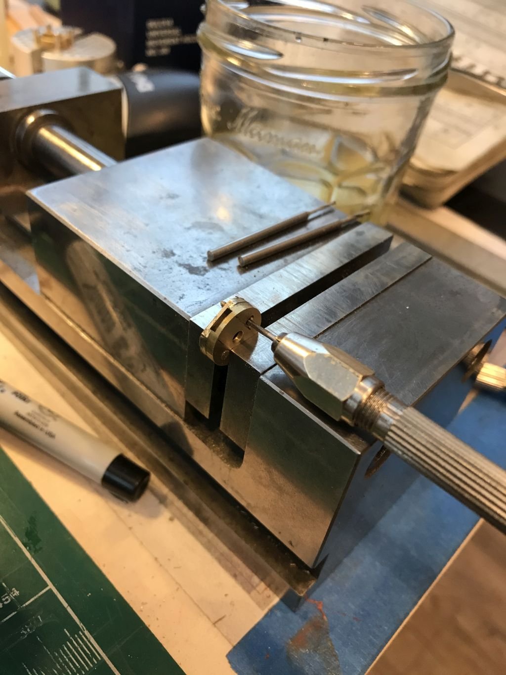
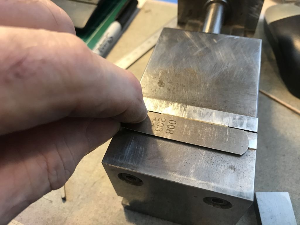
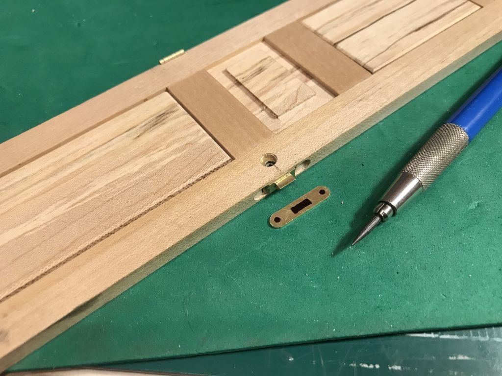
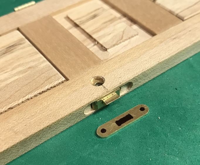
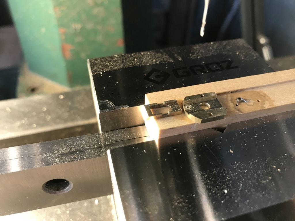
Thanks for all the nice comments and likes. the oblong plate has now been attached to the lock body and the lock is now fitted to the door next is the handle. when filing the hole for the slide plate (Latch) in order to be able to file just the right amount ie file only a particular amount away it occurred to me to use something of a known thickness as a guide. (The jaws on my Grinding vice are hard, not cutting tool hard but hard enough that they only need to be dressed occasionally.) I put the blade of the thickness gauge ont the jaw and pushed the piece to be filed down to the surface of the gauge with a flat block then tightened up the vice leaving just .008" to be filed down to the jaw. when filing the actual hole I used a different thickness the photograph was to show the principle. After getting the plate shaped and drilled I set it up in the third hand to be soldered to the main plate of the lock. Then rotated the set up over so that I could add the solder to the back side . a small sliver of solder placed with some cleaning type flux (duzall) After heating with the air soldering gun rotated it back up and released A couple more 00x90 screws to hold it into place. I I have been thinking about the handle and I am leaning toward an oval shaped one not a lever, the oval feels a bit less harsh than the lever . Michael
-
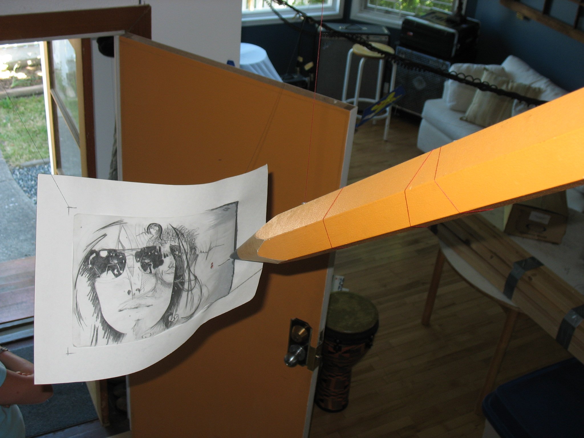
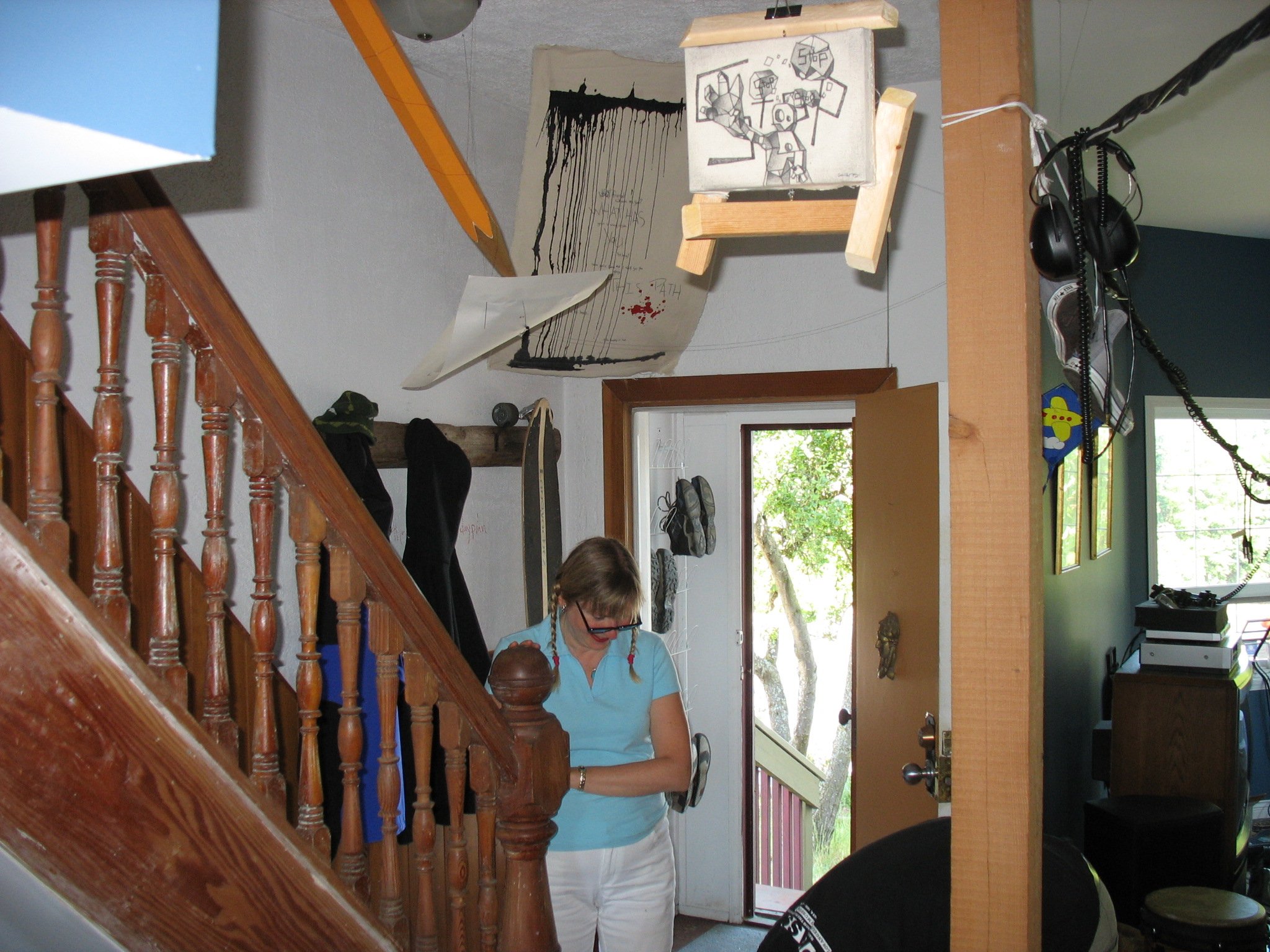
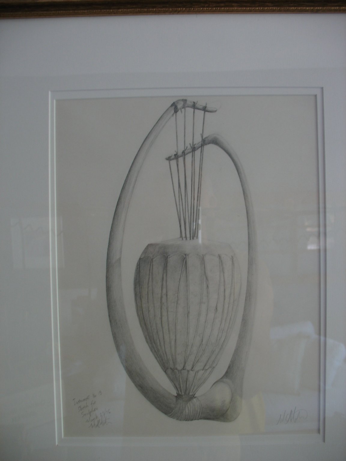
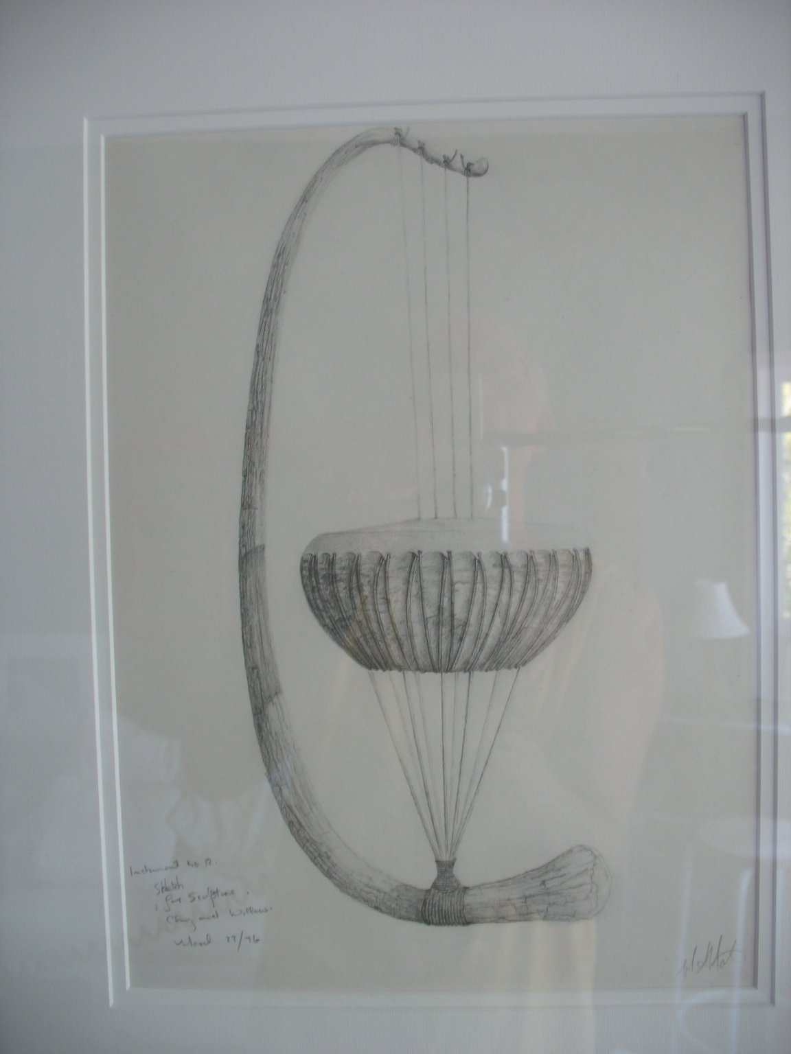
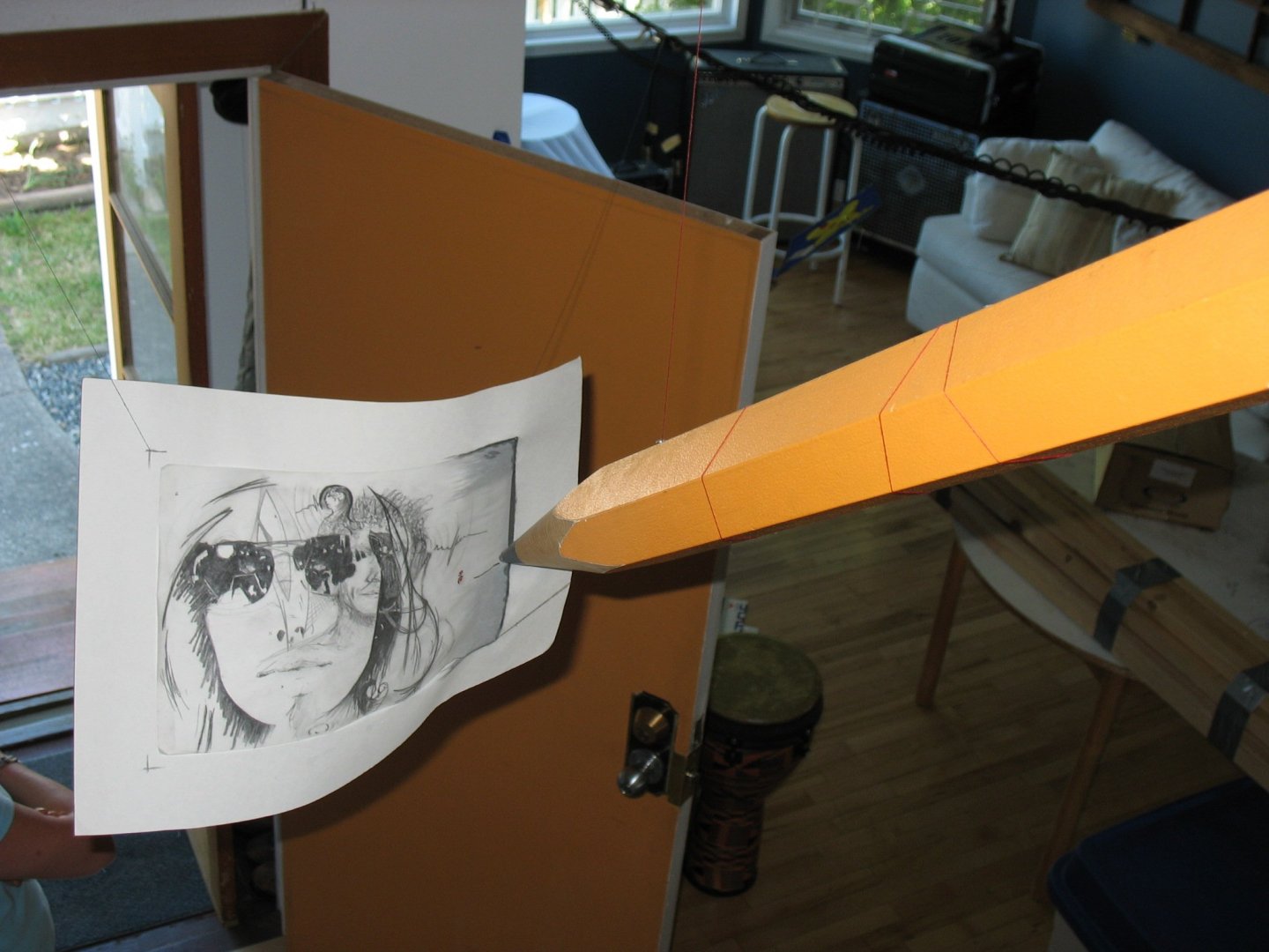
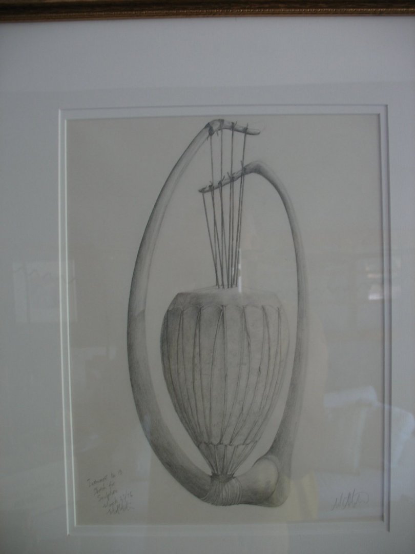
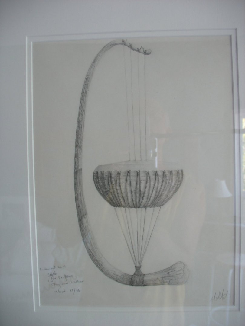
Grant it is part of this set that I made back in 2006 for my son in Victoria. LOL I actuall only made a couple of giant HB pencils for a display at the Edmonton Science Center that framed a customer comment station, at the end of the display I was able to keep the pencils, my son is an artist so I gave them to him he now has a studio in Whitehorse and has it hanging as a sign. I like to draw as well here are a couple of my drawings that my son has in Whitehorse. They are imaginary gourd type harps loosely based on the instruments that were catalogued in a book that was of the instruments of the peoples of the Congo area in Africa in the early 20th century Every once in a while I will sit and draw . So there really are giant drawing tools out there. Thank you Gaetan, I have drawn inspiration from your own work. Steve, when you get round to making shackles let me know I have a lot of pictures of the process. Ah but then I would need to install a sound system and electronics is one of those mystery subjects all I know is there is a + and a - And thanks to all who have added likes and a are following along. Michael

-
Steve sorry I missed replying to your comment, I actually did a lot of work on different ways of making shackles earlier on the build I cannot remember where in the sequence 6mm is basically a 1/4 inch no problem that's only 1/32" Kurt I have thought about a book, it would need a fair bit of work though because of all the two steps forward and one back that seems to be my way forward. LOL Thank you Druxey and Gary for your kind words. A bit more progress on the lock, first I turned a bit of hard brass to the width of the slot in the slider part then sliced a bit off on the mill then used the jewelers saw to cut the small bit to fit between the ends ready to solder in place. After the slider was filed to shape, it was placed into the body to position them ready to be glued together for drilling and tapping then I used a Walthers 00x90 tap for the screws to clamp the body halves together. I cheated and turned the 00x90 hex bolts into some small head flat head screws Next the lower body plate and the slider were drilled for the spring, I ended up with about half a dozen springs before latching onto the correct design. With the spring in place (.011) music wire spring I have miles of the stuff in anyone needs any. the door is mortised and the retaining plate is ready to be slotted and drilled then be soldered to the lower body plate. And the pencil for scale Good night Michael

-
Thank you Valeriy for your explanation, I will see what is available in Canada. Michael
-
Valeriy, beautiful workmanship on the rail assembly. Have you been using heat sinks or different temp solders for the sequencing of the assembly? I understand the small tip in order to transfer heat to a small area if the soldering iron is of a high enough wattage, but will so many small items so close together and the melt point of the solder having a range even a small one I am wondering about the heat transfer to previously assembles parts. Thanks Michael
-
Eberhard the holder is as it came in the small case I have not changed or added anything, and it also came with a separate set of nylon posts for holding watches in their case the posts I am using are for movements that are not in their case Mark thanks but this work is crude compared to a watch mechanism, think of a ladies 21 jewel Swiss watch. Geert this is absolutely why I enjoy this scale so much, it does allow me the flexibility to try to make parts that otherwise would be too small. Yes Bob and really for me the work is the joy whether it is a hinge or a set of shackles or the rigging for the topmast this scale allows me to try things that would be extremely difficult at smaller scales. I also enjoy the process of documenting the work and being able to share the ways I work, it seems only fair to me because of the immense amount I have learned from following many build logs and other areas on this amazing forum. Michael
-
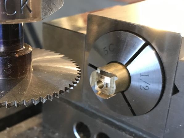
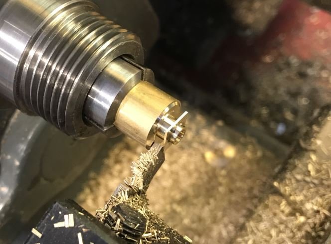
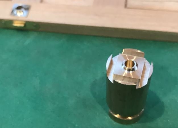
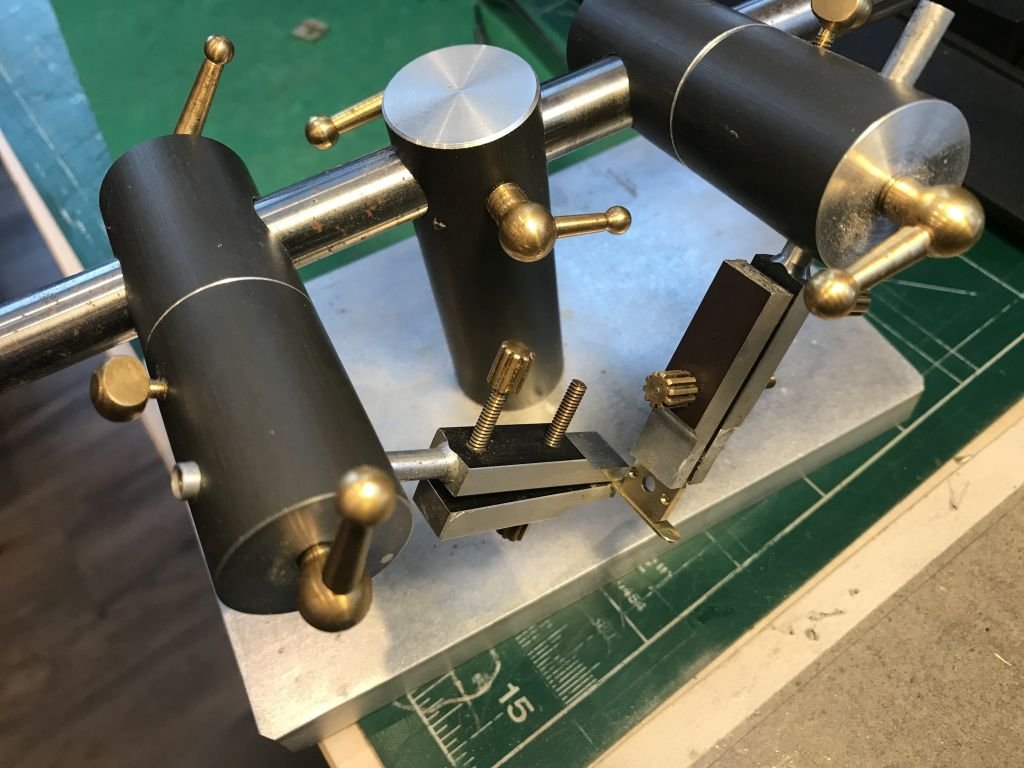
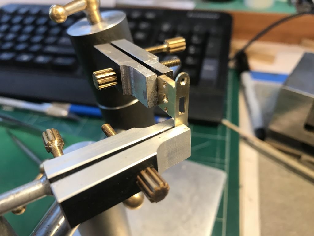
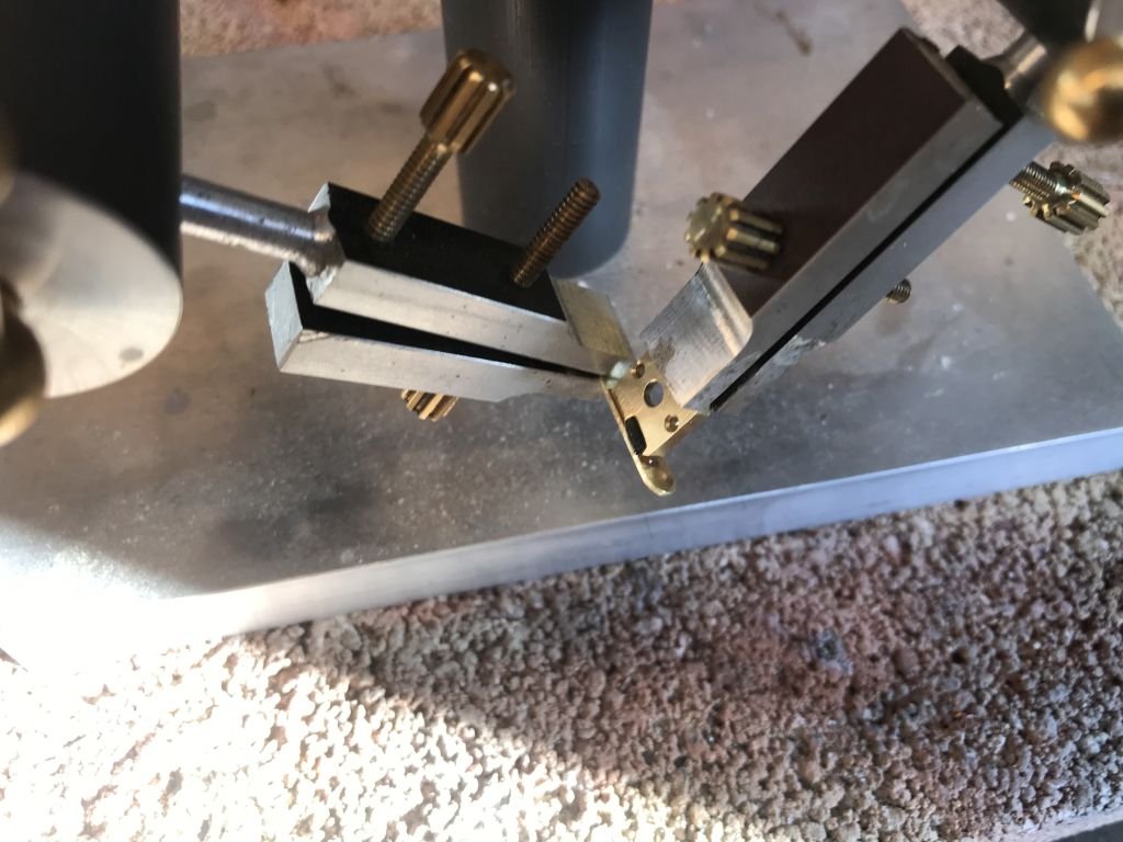
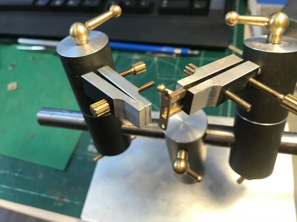
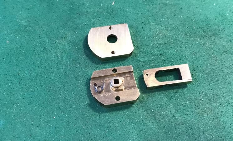
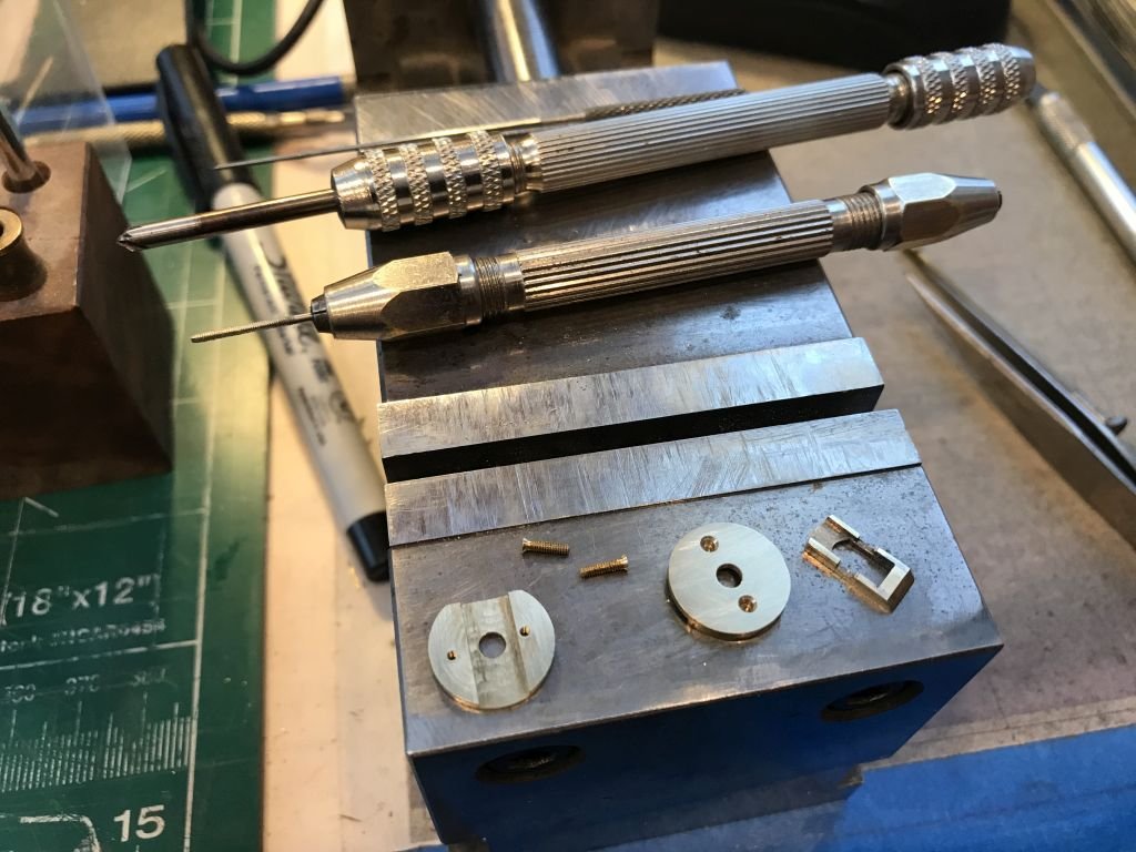
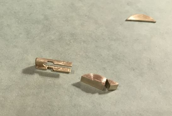
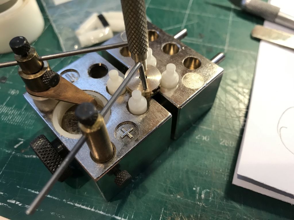
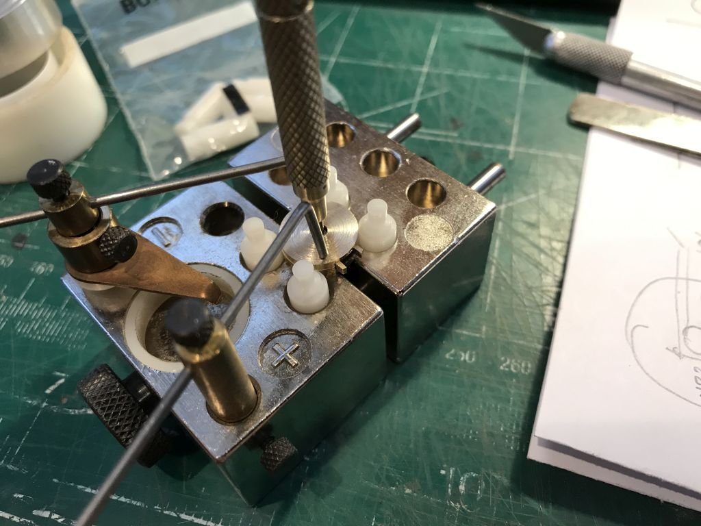
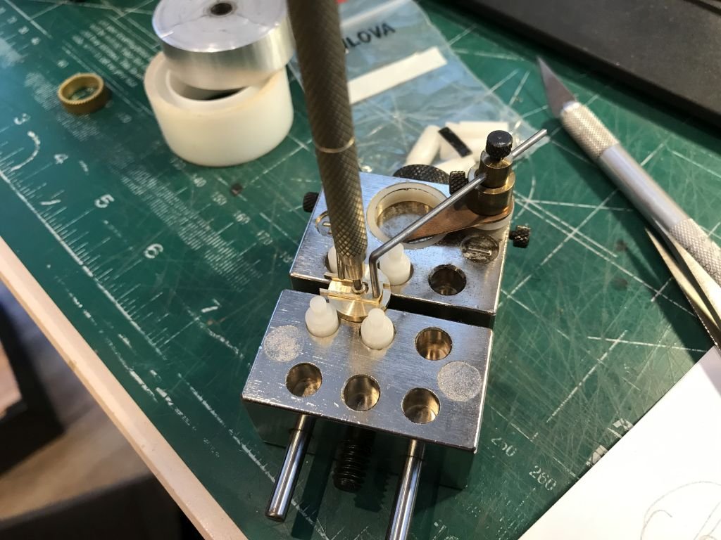
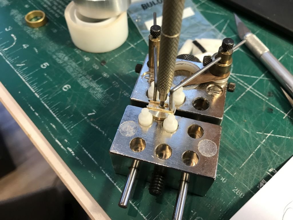
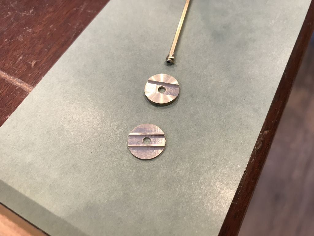
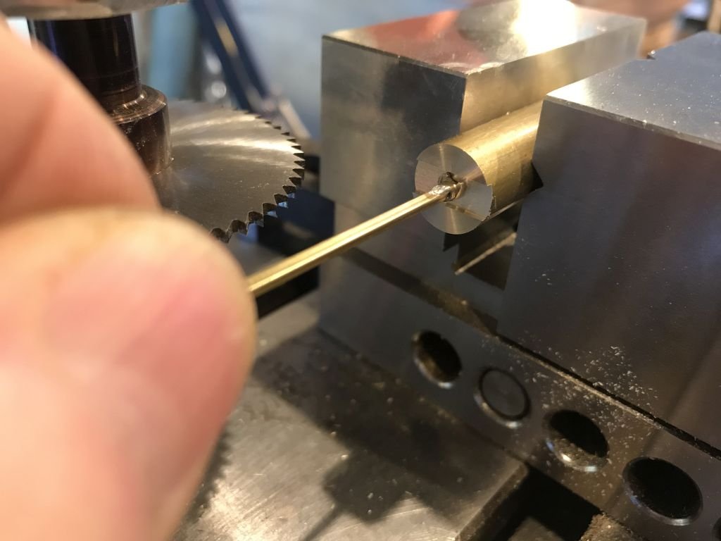
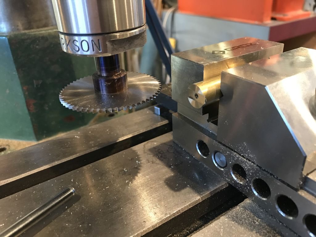
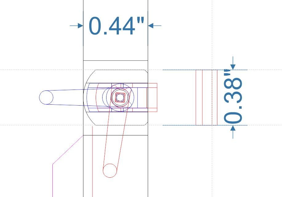
A small update I began sorting out the door lock this sketch gives a general overview of the design First some 1/2 inch diameter hard brass was prepped on the mill by cutting a slot across the hole which is .106" in diameter the slot width is .193" The pawl or central spindle was checked for clearance the square 1/16th tube was soldered into a disc of 3/16 brass that had been turned down to create a 1/32 inch flange that was shaped to create the teeth. The slider that will become the latch part was prepped again on the mill creating the tabs to engage with the pawl. The slider was fretted out with the jewelers saw. after some filing the slider was test fitted into the base plate of the lock, I have a watch holder for Bulova watches that I acquired with a bunch of watch making stuff about 10 years ago The pawl was rotated with a watch winding key to check to motion of the slider which has to move .062" back and forth. Then the top plate was fitted to further check that the slider will not jam here the slider is out or in the lock position, the latch will be soldered between the forks And in the open position Still a ways to go but I am confident that it will work. Michael


-
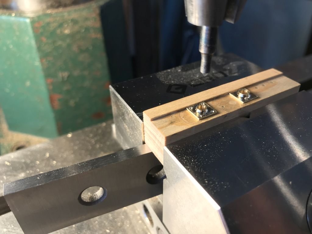
Nice methodology for the fixture. I often for get the usefulness of gluing stuff for machining. Michael
-
Yeah I expected that from you. I didn't even try looking for 1mm tap and die let alone left hand! Yes the first pic was the stock cut to a hex and drilled for the "thread" Well you could wrap a bit of fine wire around the threads and glue it on to simulate them, just remember to make it a double start and then remove one of them to give the correct spacing.😉 nice looking turnbuckles regardless. Michael
-
Homemade Styrene rack
michael mott replied to Rcboater Bill's topic in Modeling tools and Workshop Equipment
I will let you know how I get on with my racks when the materials come, so thanks again Bill for the heads up . Michael