


michael mott
-
Posts
5,200 -
Joined
-
Last visited
Content Type
Profiles
Forums
Gallery
Events
Everything posted by michael mott
-
 Today I finished the rough filling up of the ground round the track on the outside of the works. The loco is running a little rough so I will need to sort that out. Michael
 -
Ken, the Crewe works had a very extensive 18 inch gauge system in many of the buildings they used a flat steel bar for track bolted directly to the floor, and outside they used a lot of 30lb rail which was quite a bit smaller than the main standard gauge rail. They really were two totally independent systems. My model is just a cameo of the types of things that could be seen in the works around the turn of the 19 to 20th centuries. I don't have enough time during the next 30 years which would take me to 102 to do the research and build a really accurate model, especially if I want to finish the cutter and launch as well. Michael
- 35 replies
-
- 10
-

-
Hi JD, I just finished going through you entire build. What a lot of patience you have, I am fascinated by your build board having the curve of the sheer. That seems to be a great way to go, unconventional but great, as the shape is always there and apparent. your bead work is lovely. I shall follow along as well. No doubt I will need my magnifying glass to look at some of your work. Michael
-
Your model certainly look like it will last many hundreds of years mark. Michael
-
Hi Vaddoc yes you have done a nice job with the roller metal sheaves. I personally think it would look much better if you used blocks instead. The unprotected sheaves look dangerous to feet. and really a block is just a protected sheave. I'm sure you could add a couple of slabs of wood on either side of the sheaves and the they would not be so dangerous looking. Of course this is only my opinion, it is your model so you have to be happy with what you make, and you have done a wonderful job so far. Michael
-
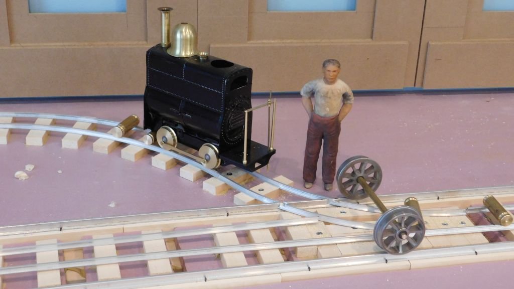
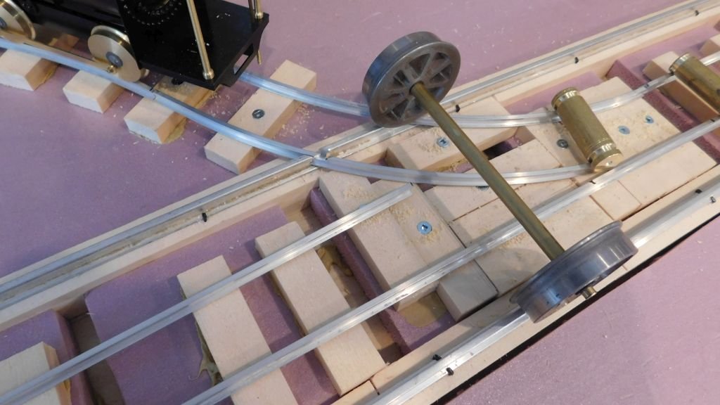
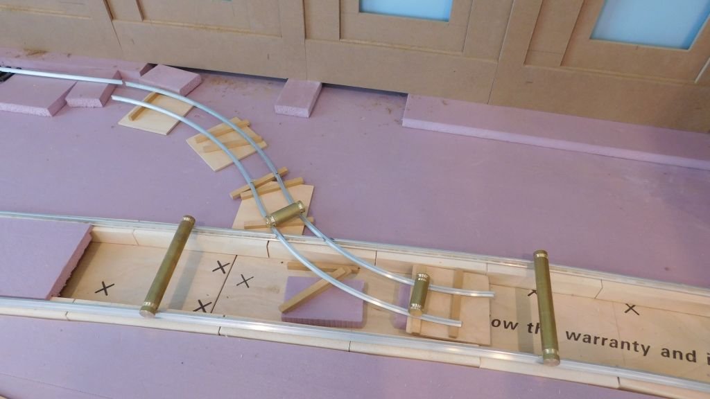
A bit of time to get the points working and the 18 inch gauge loco pushing a standard gauge axle along the straight section. Michael
-
Hi Vaddoc I would lead the sheets through turning blocks at the deck. A ring would cause a lot of friction and make it hard for the crew to "sheet in" the sail. Even with a block a winch is often needed to make that last bit of adjustment. Michael
-
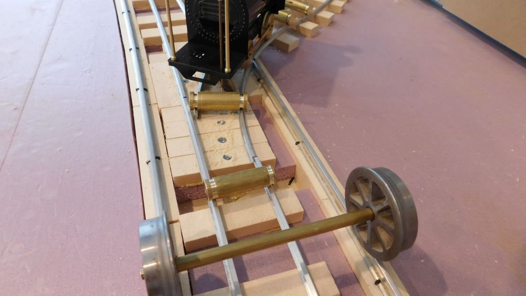
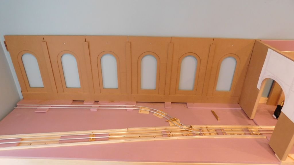
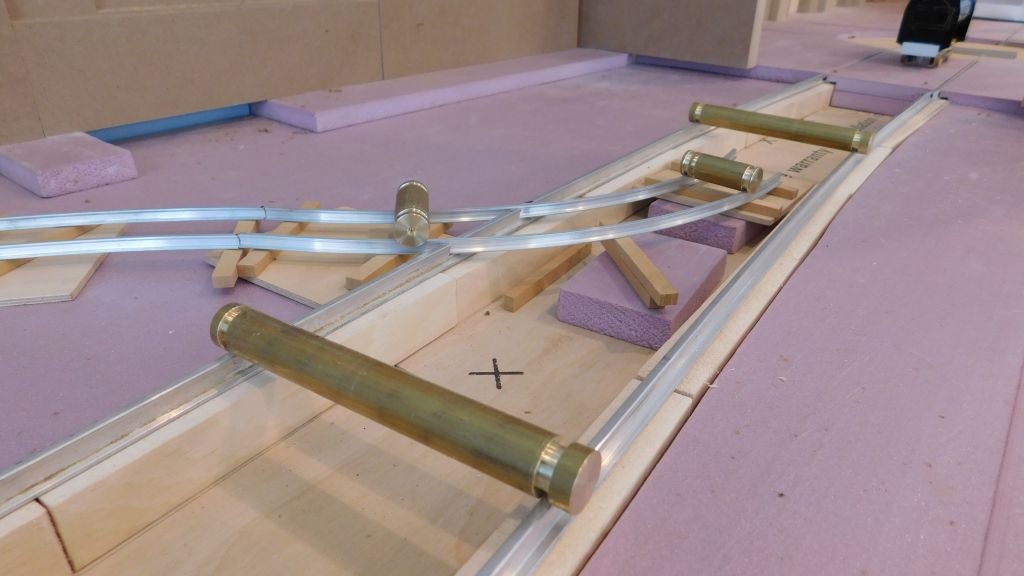
I was able to fix down the standard gauge track last night where the switch will be and then added the notches unto the narrow gauge track today, I will be deeding to add check rails for the narrow gauge because of the tight curves. Mr driver is wondering about the situation Time for some supper. Michael
- 35 replies
-
- 13
-
-
A lovely Model, Hellmuht, I really like the aged textures and the display setting. Michael
-
Hi Jack and Jan welcome to what I hope will cover a number of different types of materials and finishes and techniques. Michael
-
Wonderful looking wheel Keith! The amount of wood showing is so small that most would not notice that all the grain is in the same direction. I know if you had had more time say another couple of days, you would have glued up some wedges before turning the rings. You know I just cannot resist the occasional rib. Respectfully Michael
-
Marsalv, As others have already mentioned your workmanship is superb and of the highest calibre. You mentioned that the moldings were done on the milling machine, Are you using a combination of different shapes on the one molding or are you making the cutters as a single cutter yourself, also what speed are you using to obtain such a fine surface finish. Regards Michael
- 589 replies
-
- 4
-
-
- le gros ventre
- cargo
- (and 1 more)
-
Daniel, following your work is one of the reasons that this is my go to website when I need some inspiration and humility. Your workmanship is outstanding and helps me know that there is no substitute for doing a job with less than one's best abilities. It is a joy to watch this ship come to life. Michael
-
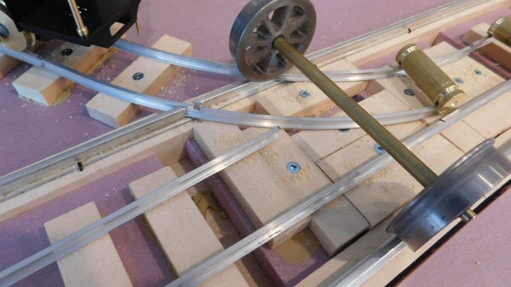
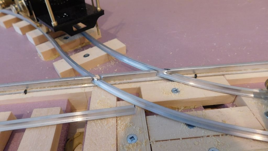
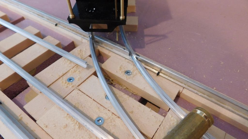
quite right Druxey there certainly will be gaps for the flanges This picture shows it a little more clearly, I have been shaping the rails and there will be enough clearance in both rail sizes for the wheels of each to clear. This overhead shot gives a better view of the way the track will set. The points will function as a normal set will function. The most fiddly part will be filing the gaps in the large and small rails at the cross over place. One of the comments in the Crewe book is that most of the points on the narrow gauge were kicked over by the driver when needing to change tracks. Mark and Egilman welcome to this new project. Michael
- 35 replies
-
- 12
-
-
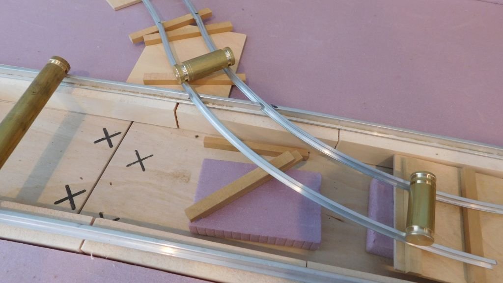
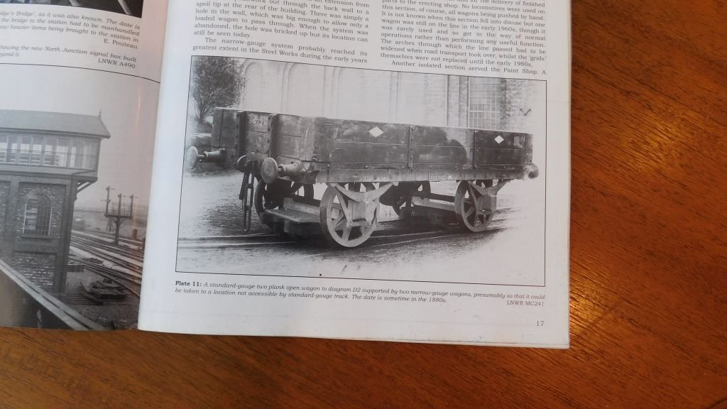
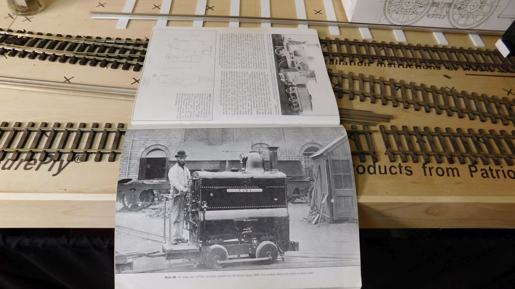
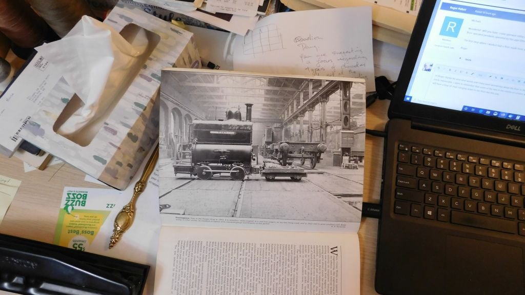
Thank you Yves Thanks Druxey , I am always a b it hesitant about posting about the railway stuff here because I know I should be posting about the cutter and boat related stuff. That said I really do enjoy reading about all the wonderful work that so many do on this site. it is still my favourite forum for the warmth and sharing that occurs here. So apologies for not being around for a while. Hi Moab Yes I call them rabbit holes it is so easy to get tripped up by them, and then away we fall. Having some interesting decisions about how to deal with the crossing and points (switch) inside the standard gauge track because I did not want to have the large rail cut into a short piece between the narrow gauge track. Most of the track will be buried up to the rail height anyway with ground texture as in these images. Again these images are credited to Edward Talbot and Clive Taylor book about the Crewe Works narrow gauge system. The reason that I have the narrow gauge join the standard gauge track just before the entry into the works is to avoid having a small door next to the large one, it just looked odd. Once the track is all laid The Idea is to be able to move a standard gauge wagon on the narrow gauge trucks as in the picture so that it theoretically can be moved to another part of the works with the narrow gauge loco. I love the outfit that the chap is dressed in so will have to make a figure dressed the same way. Michael
- 35 replies
-
- 14
-
-
Wonderful to see the final pictures Eric, you must be satisfied with the results. A beautiful looking ship. Good luck with the move of your in laws not a good time as you say with all the restrictions in place. Stay safe and enjoy your next model and the prepping of the lumber from your own farm. It is a great feeling to take the time to take the raw material and see the change from tree to model lumber. and the wood will not have been cooked during the drying process so the natural oils in the wood are still there and it makes a difference to the colour and texture of the finished wood. Michael
- 599 replies
-
- 3
-
-
- sidewheeler
- arabia
- (and 4 more)
-
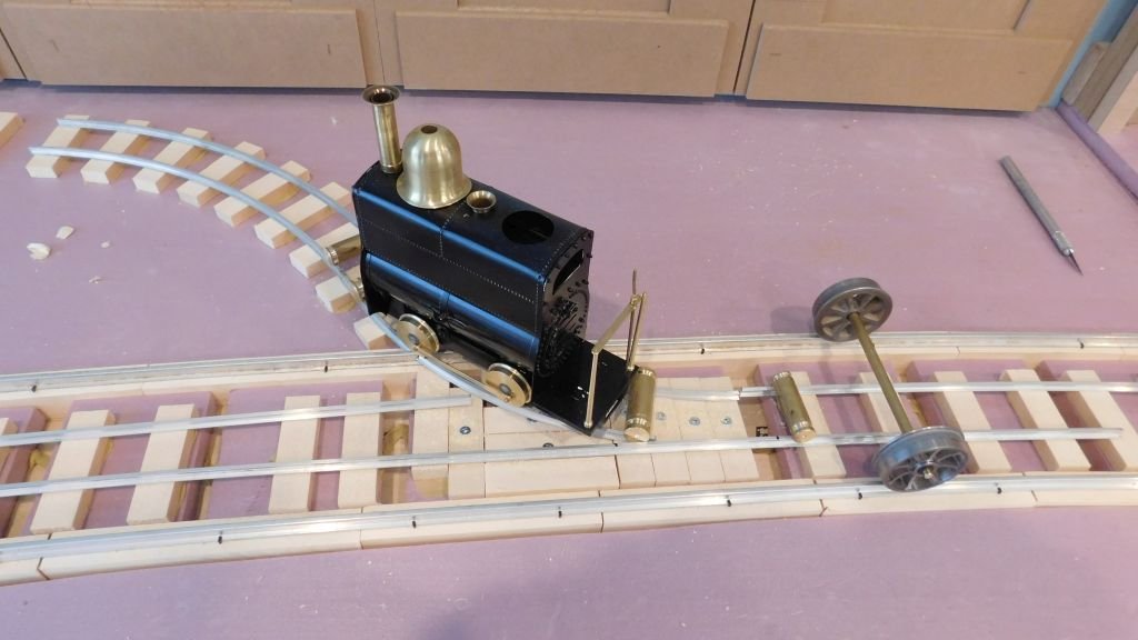
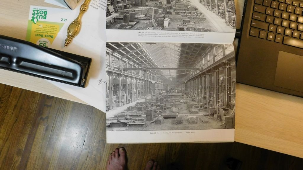
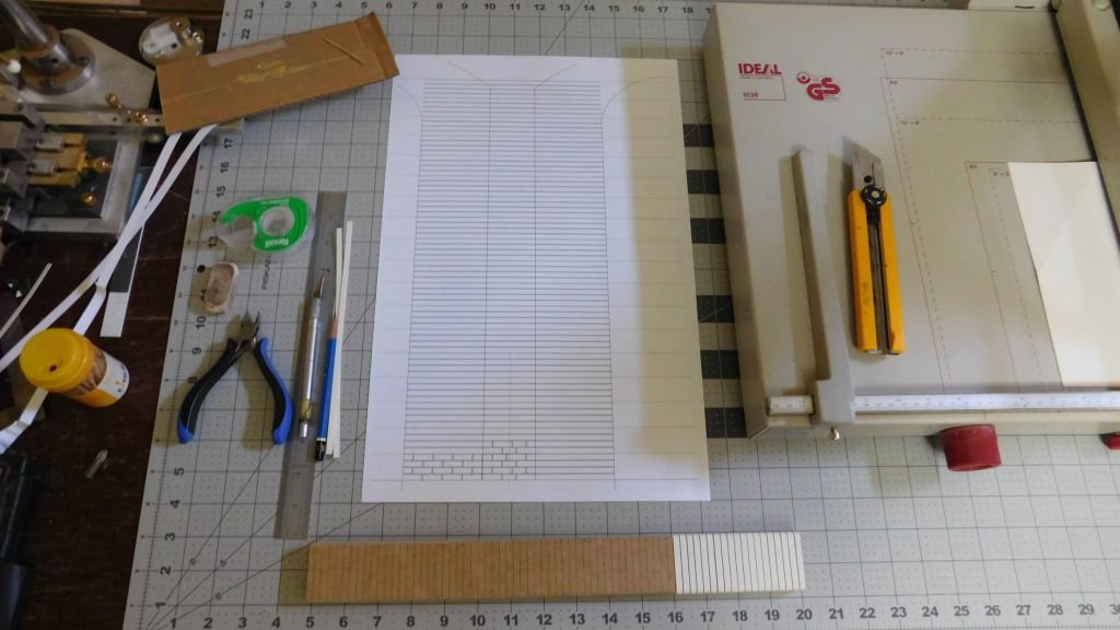
Hi Roger thanks for your kind words and I have been wondering about the floor in the workshop and it occurred to me that wood blocks on end would be a practical floor, forgiving and yet easily replaceable. I seem to remember that some of the sets in the streets of London were wood as well especially around the tram tracks. The overhead crane is is not all that heavy duty and will have a loop of chain hanging down to the floor like this one. In Edward Talbot and Clive Taylor's Book "Crewe Works Narrow Gauge System" published by the London & North Western Railway Society. And this one shows the flooring in fairly good detail and I had wondered if the sets were wood . Currently I an sorting out the best way to tackle all the brickwork, which will likely be done by adding strips if 140lb watercolour paper and cutting out the vertical gaps as once the strips are glued onto the backing. like this. At least I cannot ever claim to not having something to occupy my time. It's a good thing that I am not into model aeroplanes as well as boats and trains. here is a shot of the little Crew loco running That's all for now Michael
- 35 replies
-
- 15
-
-
Hi Vaddoc, Mark makes some good points. A couple of observations I noticed that you have a fairly large bagginess diagonally across the mainsail, to correct this you need to either raise the gaff at the mast which will also entail raising the peak of the gaff as well, or you need to pull down on the boom at the mast. I am wondering why you have laced the foot of the main sail as it restricts the airfoil shape near the bottom, I have preferred to have my mainsail on my sailboat loose footed and it allows for a nice shape. I agree with Mark regarding blocks on the clews this is not a good practice and also creates a catch when coming about as the block has to pass over the forestay of the sail below it especially with the two upper jibs. When changing tacks you want those sheets to flow as smoothly as possible across from one side to the other. It is better to lead the sheet through a fairlead of some sort even the sheaves that you have made and then lead them to a winch to be adjusted and cleated putting multiple purchases on the sheets will cause no end of difficulties when under sail and changing tacks the sheets are often let off in a hurray and the sail whips around the mast as in the staysail and over the forestays of the next two. In my opinion it would be better to use a shackle to attach the sheets to the jibs there is also a simple looping type fixing which does not use ant hardware at all. Michael
-
Hi Vaddoc, just catching up, wow you have done a lot of work the rigging and sails look wonderful. Michael
-
Rob the combination of the furled and billowing sails is wonderful, You are show you excellent skills with the paper sails. Michael
-
Hello Keith it has been a little while since looking in, My you have been doing outstanding work on this yacht. Michael