
HOLIDAY DONATION DRIVE - SUPPORT MSW - DO YOUR PART TO KEEP THIS GREAT FORUM GOING! (Only 13 donations so far - C'mon guys!)
×


michael mott
-
Posts
5,195 -
Joined
-
Last visited
Content Type
Profiles
Forums
Gallery
Events
Everything posted by michael mott
-
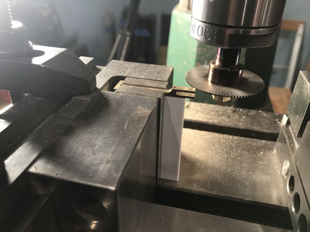
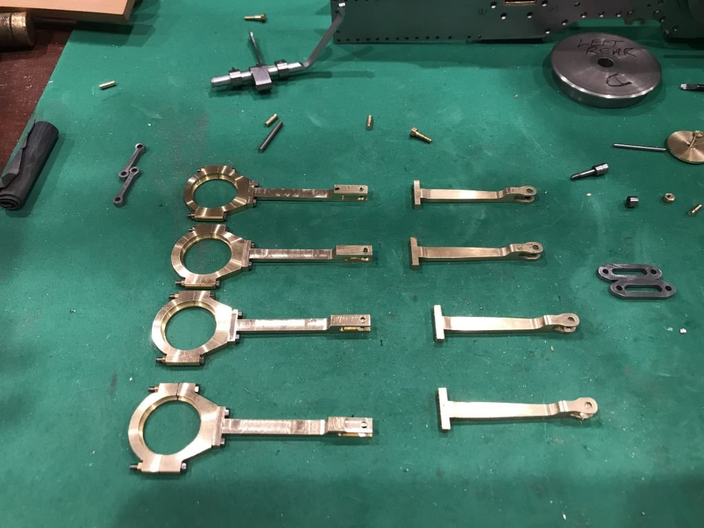
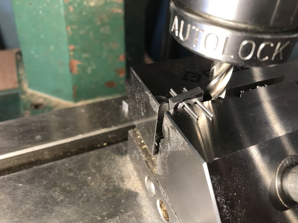
 Happy new year to everyone. Things are getting to be quite challenging at this stage the more parts that get made and that need to interact with other parts is becoming difficult to "get by" with small inaccuracies. The eccentric rods there are 4 of them have to be narrow enough to fit between the hanging links from the weight shaft but be able to have connecting pins held in place (in full size practice by taper pins) the previous ones I made were too wide and the space in which the straight link was pinned was too wide as well. These are the radius rod hangers they are OK disassembly (again) So I though I would make them over with some steel I did one as a test (didn't work out too well) so another test using some hard brass (a second failure) Then decided to rethink the whole thing and went back to the drawing board (Auto-cad) and made some adjustments to the tolerances and dimensions of the arms keeping the lengths the same as these are critical for the valve timing. and started over on the arms. They are not "perfect' but will work. One of the areas that I needed to change the most was the slot into which the straight link fitted the steel of the link is .075" thick and the original slot was cut with an end mill that I had that was .090" I thought this would be OK but it wasn't A friend who has built some larger model steam engines told me that you need to ensure that there is a bit of "give" in the gaps and linkages in order that things do not bind because the axles are sprung and move in a couple of planes (basically in a twisting motion when moving over irregularities on the track) I found out that there is also a limit to how much "slop" one need to build in. I used a slotting saw the second time around and made the fit much closer. I also simplified the shape a little from the Actual shape of the full size loco, in order to simplify the manufacture of the part. I used my old grinding vice that I made as an apprentice as it allowed me to hod the part more easily than the regular milling vice. After the slots were cut I used some filing buttons to shape the ends. The split large ends of the eccentric rods were thinned down a little on a temporary faceplate jig. I used the same plate to trim up the straight link hangers that were made from some free machining hex steel. I am going to have to make a special jig to assemble the links to the radius rods and the eccentrics before putting them as sub assemblies into the frames. I take my hat off to the watchmakers in the crowd. Michael
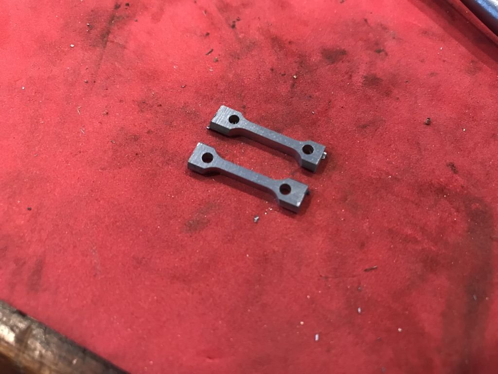
- 96 replies
-
- 11
-

-
Happy new year Keith to you and your family, lovely brass work, nice job on the sanding for the bowsprit as well. Michael
-
"300 to 350 blocks" Wow! Rob great to be catching up you are doing an amazing job on all the details, I don't think I could do it, i am having enough of a challenge with a single mast. the progress looks fantastic. Michael
- 1,208 replies
-
- 2
-
-
- great republic
- clipper
- (and 1 more)
-
Hi Mike, First Congratulations on you new Daughter, and a happy new year to you and your Family. The model is coming along beautifully your workbench with the built in vice looks like a very nice bit of kit. I had to smile at you comment about the time spent fairing earlier would have made the planking easier. I am sure we have all been there. It is interesting seeing your fingers inside the hull and it always surprises me how small some of these areas are that require so much fine work to be accomplished inside them. looks like you have mastered them very nicely. Michael
- 968 replies
-
- 6
-
-
- hahn
- oliver cromwell
- (and 1 more)
-
First a happy new year to you and your family Vaddoc. What an interesting thread to follow, your tenacity at resolving the details of the lines is admirable and point to the challenges of transposing working methodology. Think of any of the "Old Trades" and relate those to modern methods and technology and you run into all the same issues it seems from my few observations and experience. I used to watch my father mend our shoes on a three cornered shoe last, just as one simple example. finding a cobbler these days is a challenge in itself. your skills with the cad drawing are way beyond anything that I am capable of, I do know a little cad and am using an early generation Auto-Cad which is OK for the engineering type drawings that I do but even so I think in a 2D pencil way while using it and still have trouble with splines curves in auto-cad. It is the reason I turned to a "drawing Program" Corel Draw for working out the lines of my boat model-work, I found it much easier to draw using the 2D mindset I had been taught with a pencil and paper, on the screen with the drawing program especially with the curves. As you have already realized in our attempts to make "accurate" models of vessels that were made in an earlier time using the "80/20" rule, it is difficult to work that way with our modern tools. It is as if we are forced to correct the slight errors to satisfy ourselves because we have been coached into thinking that perfection is the "holy grail". I suspect most of us fall into that mindset on some level. I can tell you that I struggle with it all the time, my little steam engine model is beginning to feel like I am watchmaking and it is becoming very challenging and frustrating, making and remaking parts to match the tolerances of the drawings without the "watchmaking tooling". I forget who said that the sight differences when we build the hull are easily corrected with a bit of 120 grit, are worth keeping in mind. I think it is our nature though to want to make it "Perfect" looking at you other builds I am sure that you will do an outstanding job on this model when you start making that "scale" sawdust. 🙂 Michael
-
Lovely work on the deck furniture Keith, I like the way you used the card to position parts accurately, simple methods, we often forget. Michael
-
Wow! Danny you make working with the card look easy, and you keep it all so clean. Michael
-
Following along GL the casting turned out alright, even if you had some issues with getting it out of the mold. a very slight taper from the top to the bottom about 2degrees and the and smearing the wood with Vaseline will make the next keel that you cast slide out of the mold much easier. Michael
-
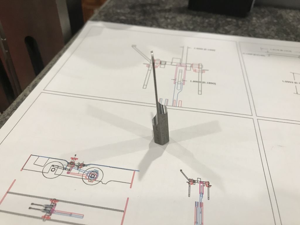
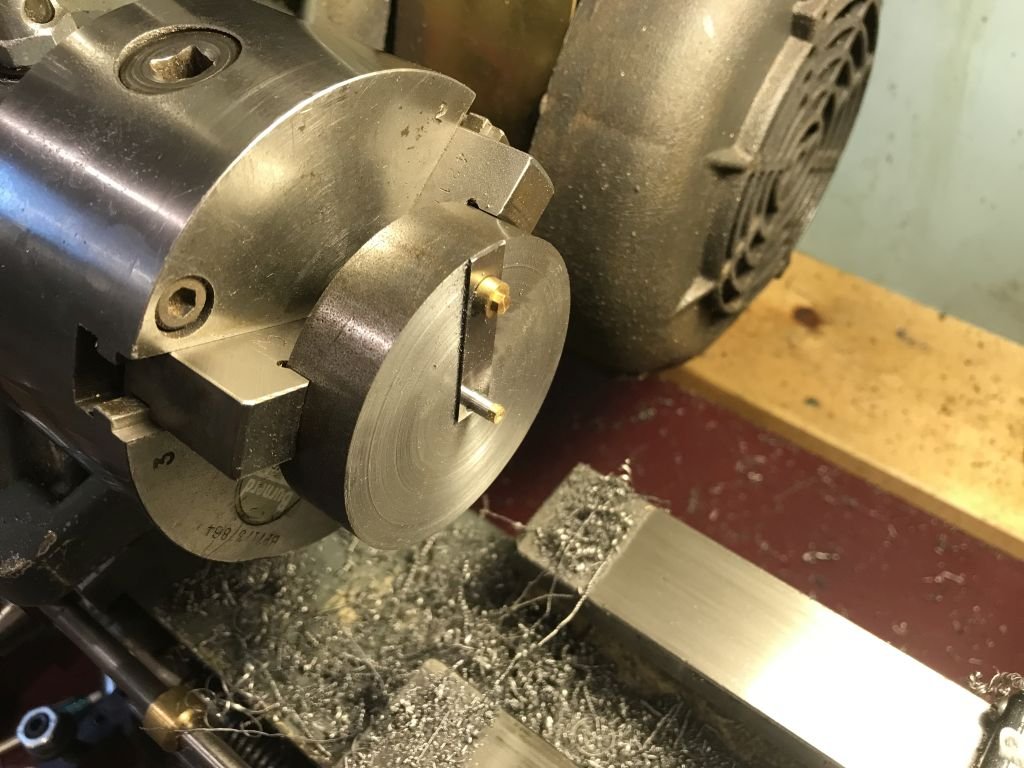
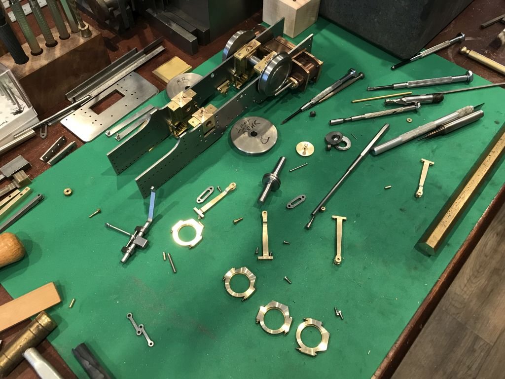
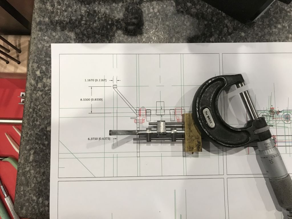
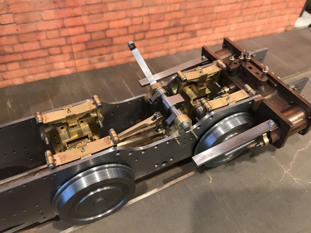
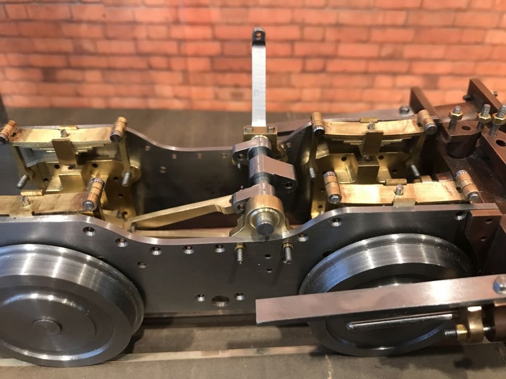
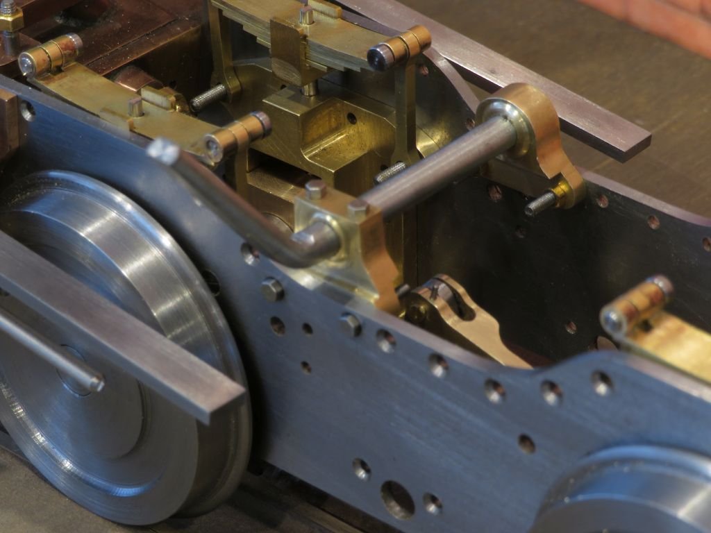
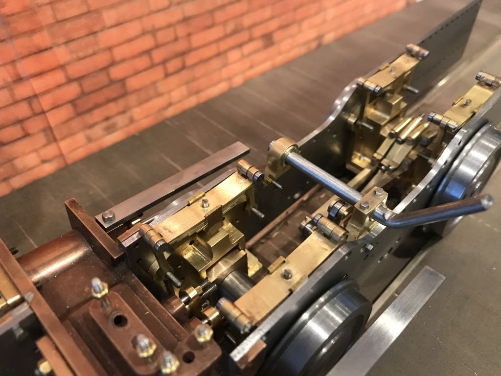
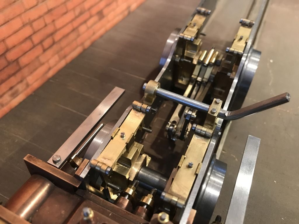
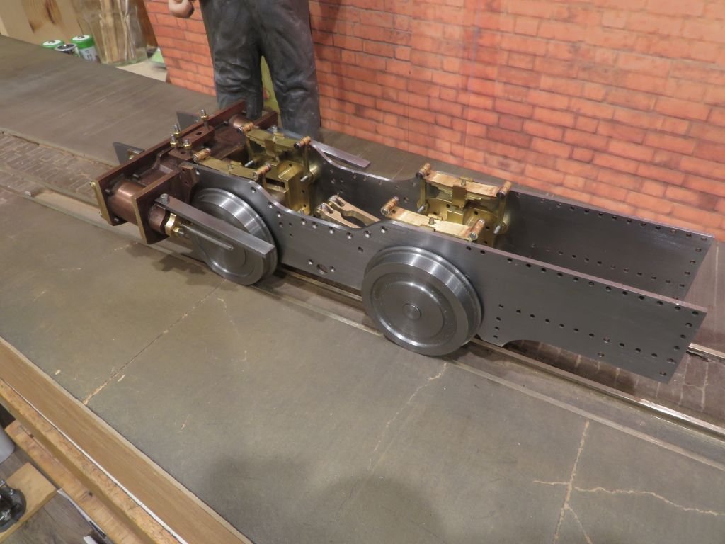
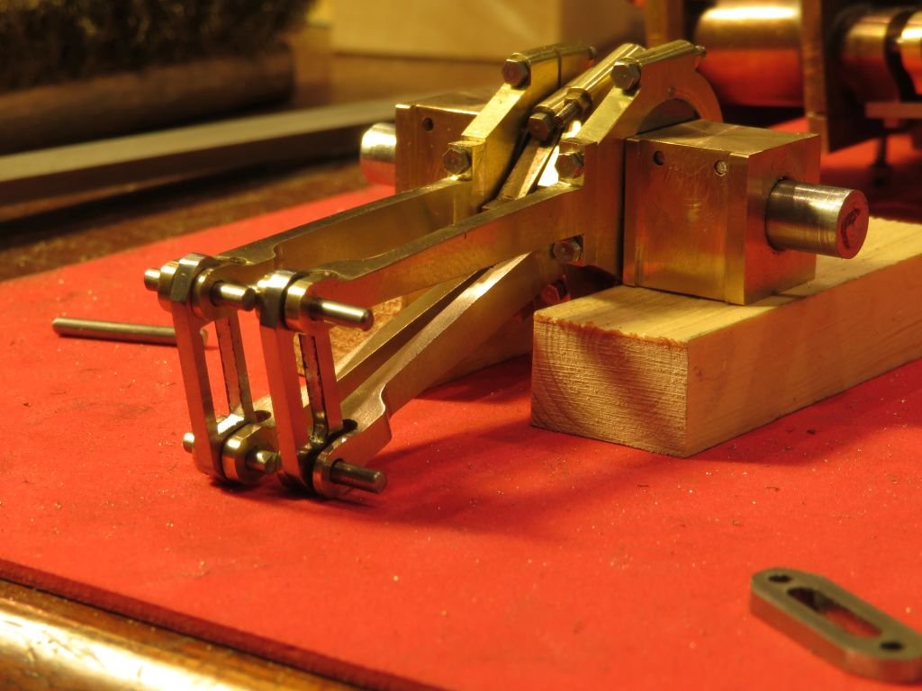
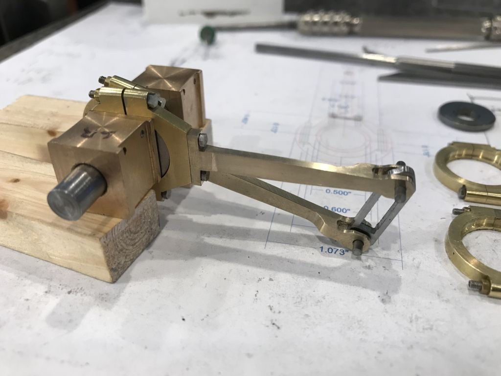
Another update the weight-shaft has now been finished and the arms are glued to the shaft ready to be pinned. The arms were machined from some stress free 1144 steel bar stock. then a jig made to hold them in the correct relationship to each other and glued with some CA glue in order to pin them with some taper pins. The sequence shows the relationship to the rest of the valve train. next the lifting arms and work out how the gett all these bits fitted together with my large fingers. Michael
- 96 replies
-
- 11
-
-
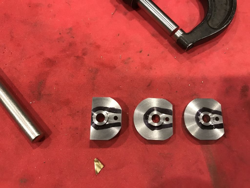
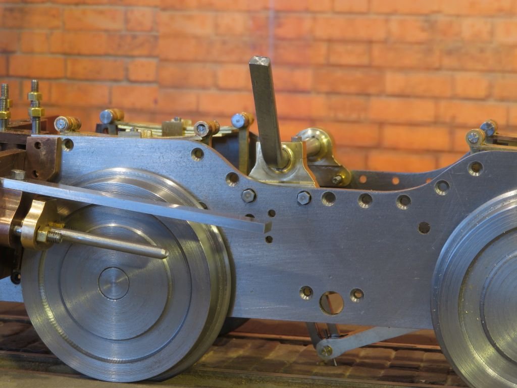
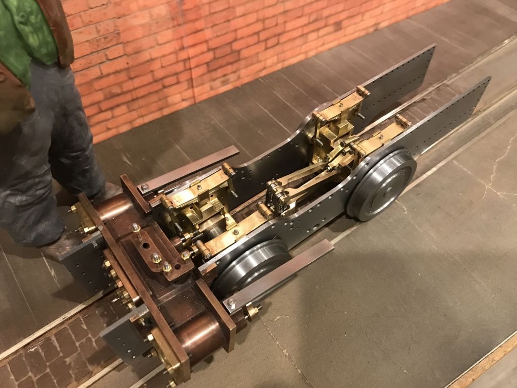
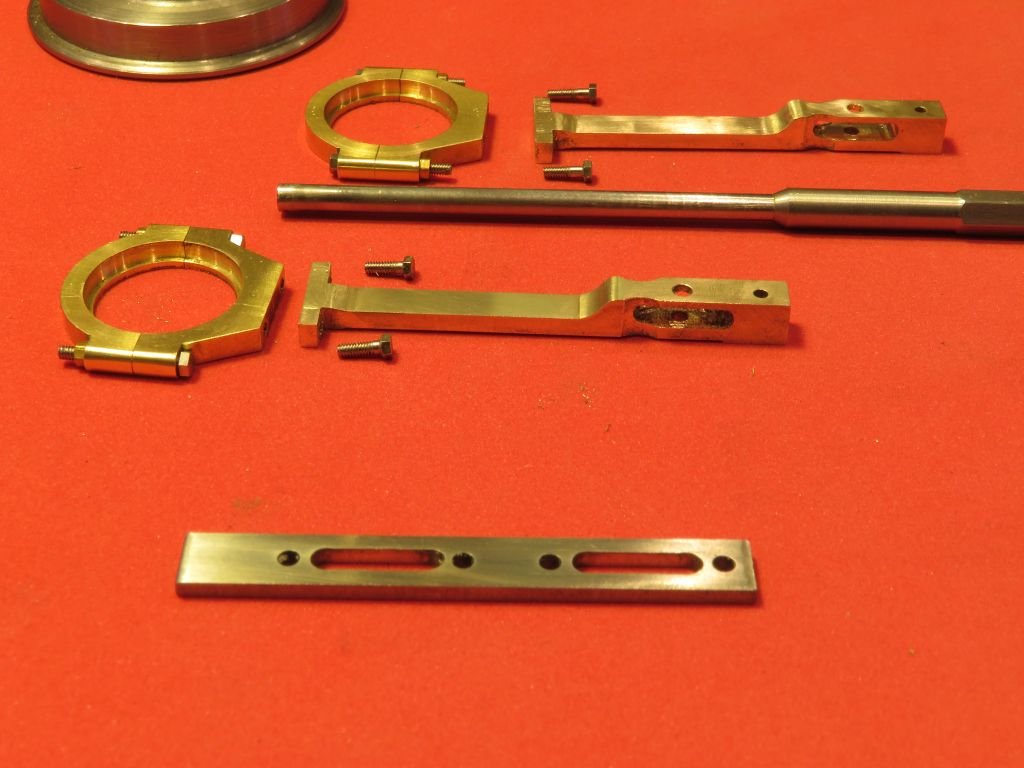
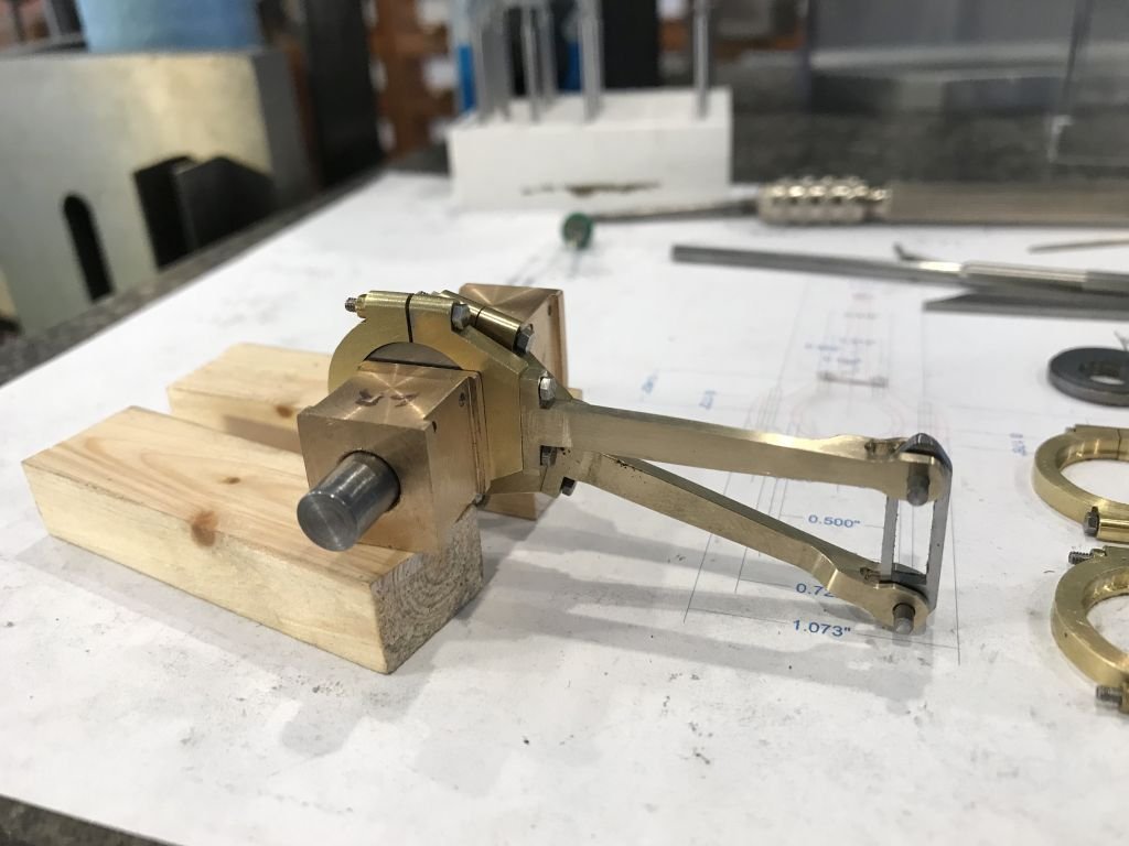
The shaft to hold the arms (weight Shaft) has been fitted the brackets were a bit fiddly to make. they were machined up from a couple of hard brass blanks of 7/8 diam brass rod. The end of the shaft that is bent up will form the bottom connecting point to the reversing lever that is attached to the side of the boiler so it is unfinished until the rest of the linkage is fitted. The lifting arms will come next and be pinned to the weight shaft. hence the reason for the split bracket on the one side. Once the arms are attached the shaft will not be able to be slipped out of the brackets without removing the top of the bracket on the left side. Michael
-
Thank you for your explanation Andy I did not know that background, can you recommend any particular reading on the subject? Michael
-
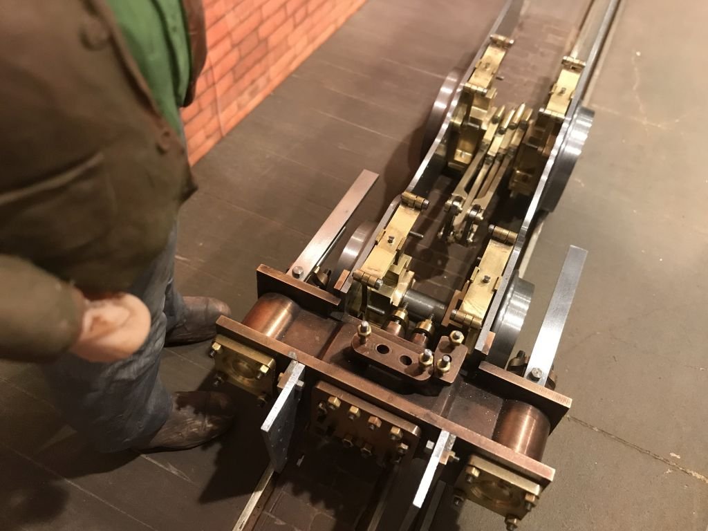
hello Jan I cannot answer your question with any real knowledge as to why the designers choose one method over another other than that space restriction or aesthetics. here is a picture of the actual locomotive that is in the narrow gauge museum in Wales. Michael
-
Jan I have thought about that a great deal, and then what comes to mind is the immense amount of work that goes into the building of a ship model like the Young America and how much incredible joinery and elements that will be very difficult to see, and some not at all. Good afternoon Vaddoc the lubrication was done with oilers in hand in some areas, others used cups within castings that were topped up again by hand held oil cans. The other thing was to use bronze bearings on steel. Oil is added to the steam to lubricate the pistons and slide valves. There are a couple of holes in the frames for reaching difficult locations. The space between the frames was also open so many spots could be reached easily with a long spout oil can. Michael
-
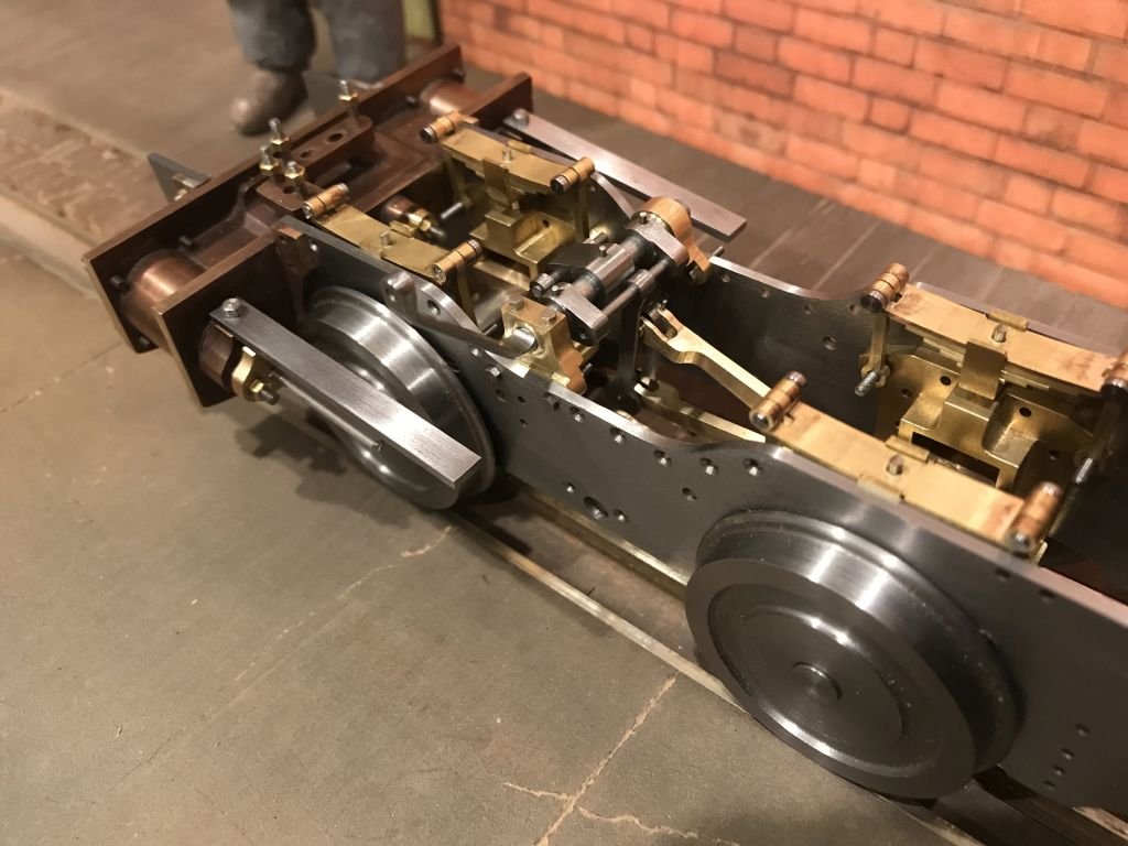
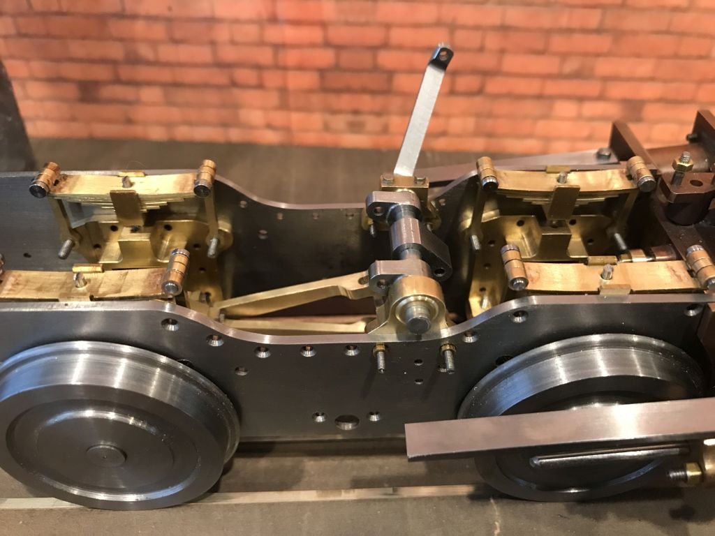
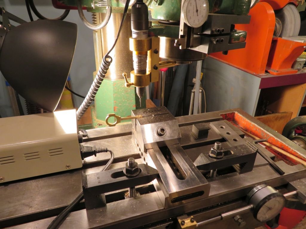
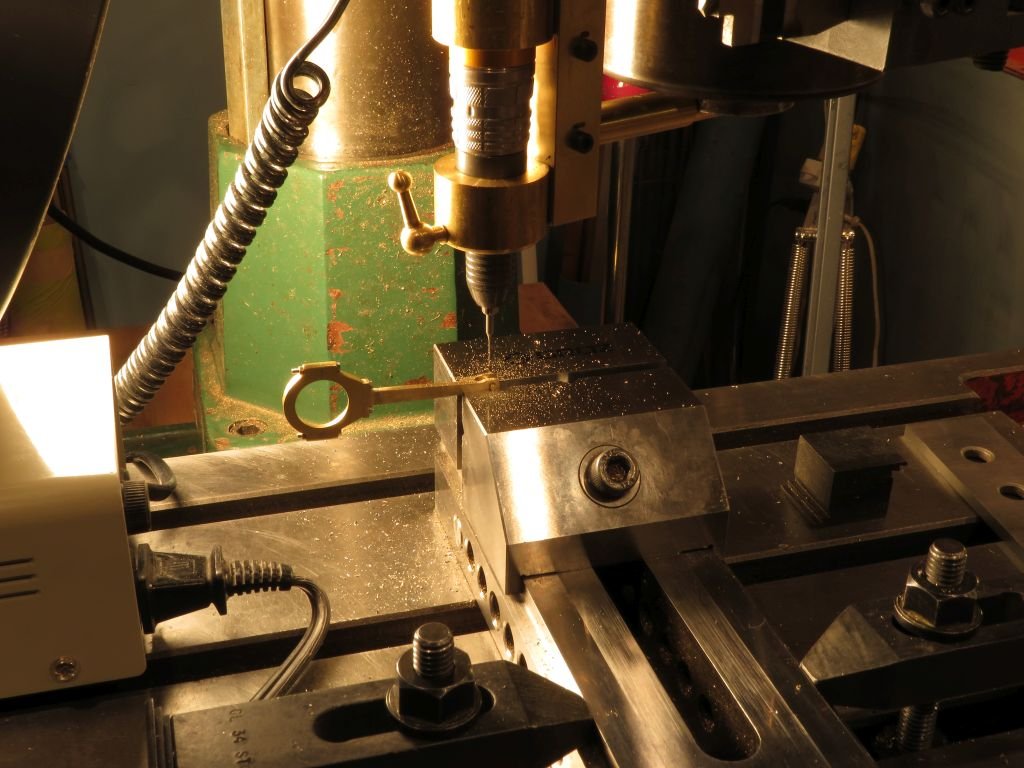
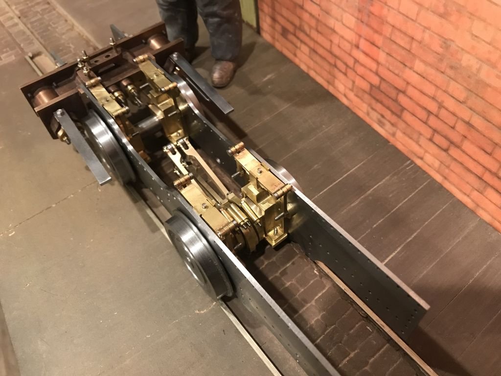
Druxey and Richard, thanks for the Kind remarks, and thanks to all who are following along and pushing the like button. I do appreciate them. I did drill and fit the taper pins into the slightly wider side of the forks the taper-pins just graze the retaining pin for the straight links. I used a .023 thou drill bit for the work. The first three shots cover the drilling and reaming of the holes. Then a few shots of the axle assembled back into the frames it is getting crowded in there! Time to put up my feet now for the night. Michael
- 96 replies
-
- 12
-
-
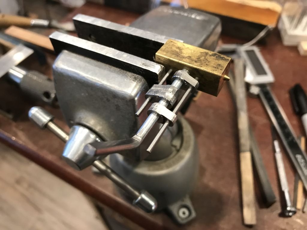
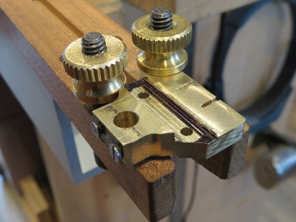
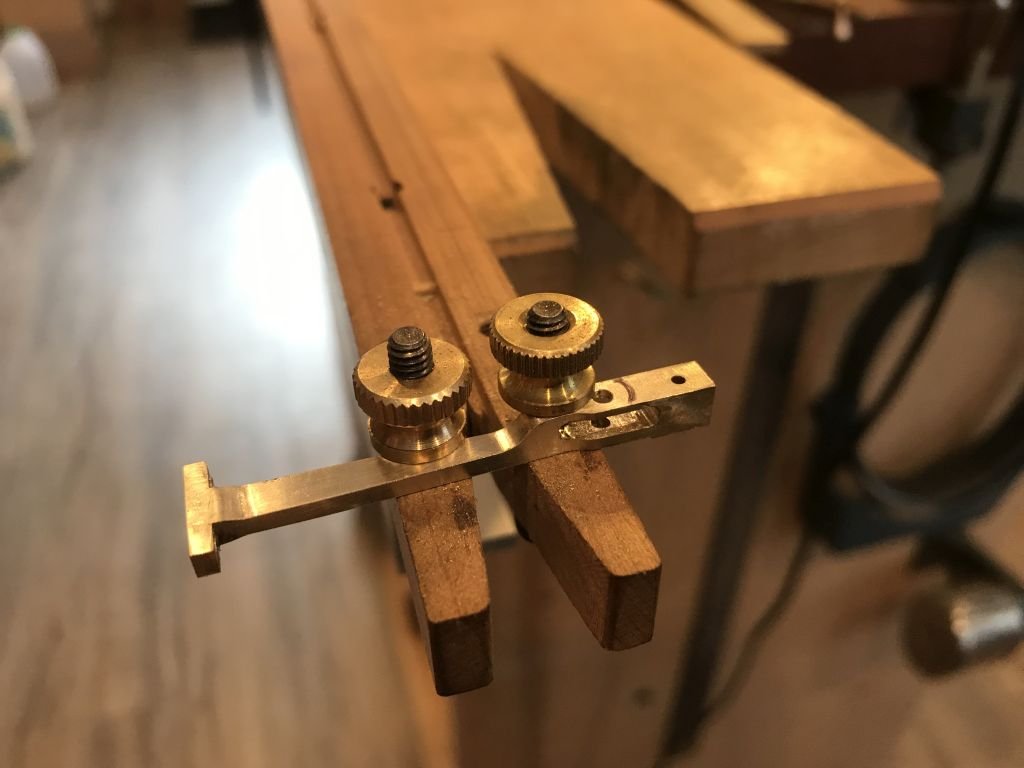
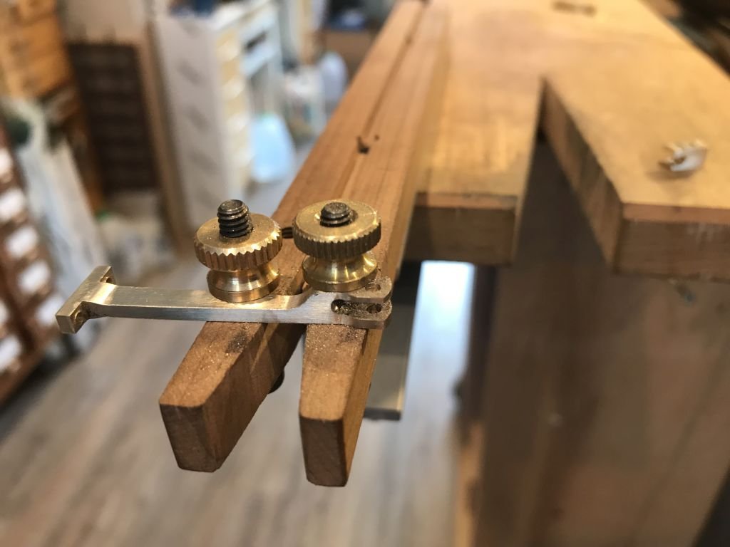
Hi Druxey, thanks for the kind words. The bench pin has two 6x32 Allen head cap screws threaded up from the bottom and a couple of the thumb nuts from Home depot to act as hold downs, I did design it for myself to relieve the ache in my fingers while holding tiny parts. and it really works nicely, I also put a groove along the long axis in order to hold round tube or solid and the thumb nuts keep that snug for cutting onto the ends. The variations on this Idea are quite broad and eliminate the need to fiddle with clamps. Michael
-
Keith in the picture of the struts that show the extreme angle (definitely a trip hazard) the top of the rail appears to be lower that amidships or is it just my aging eyes perhaps that has something to do with the greater angle. Michael
-
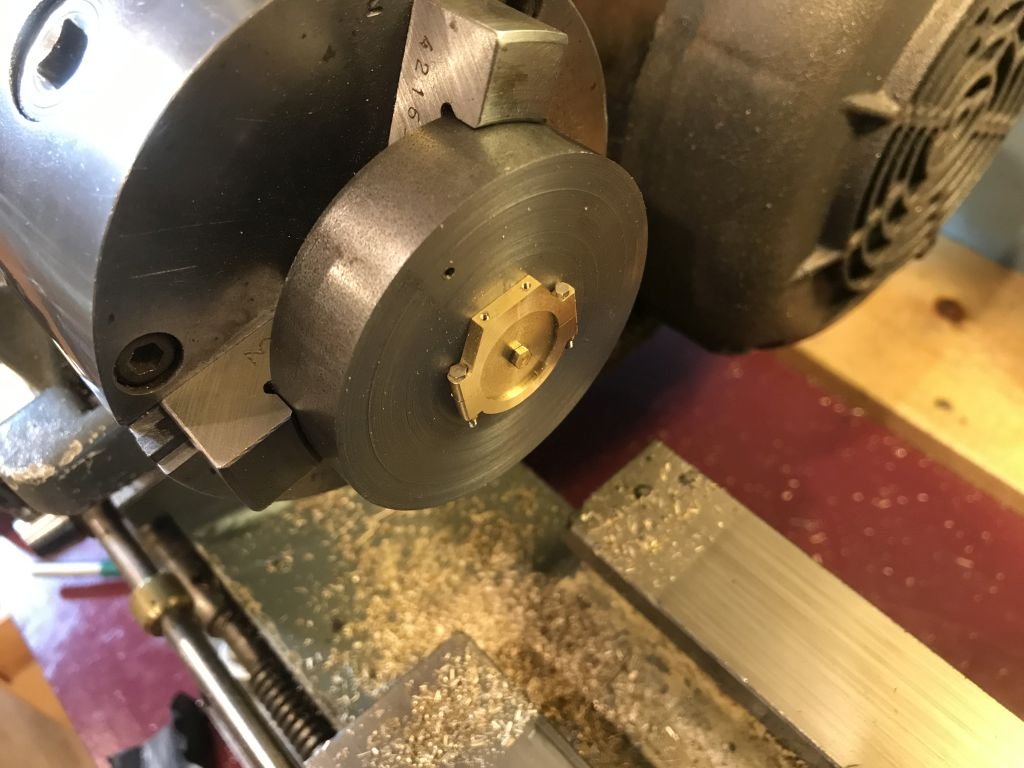
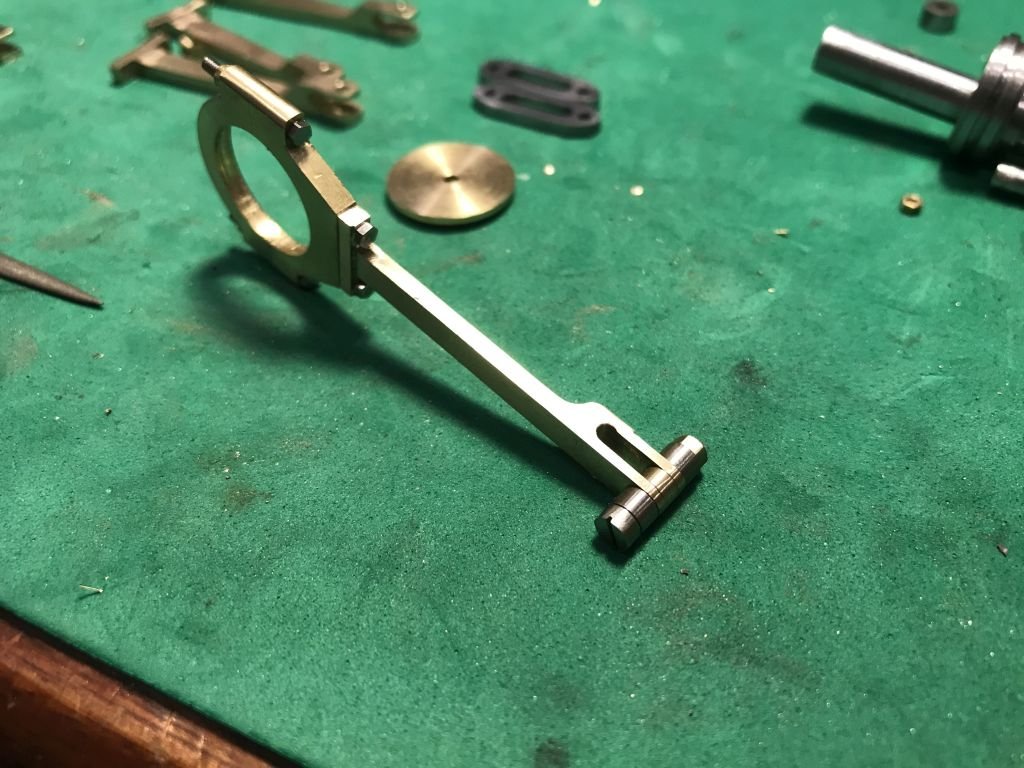
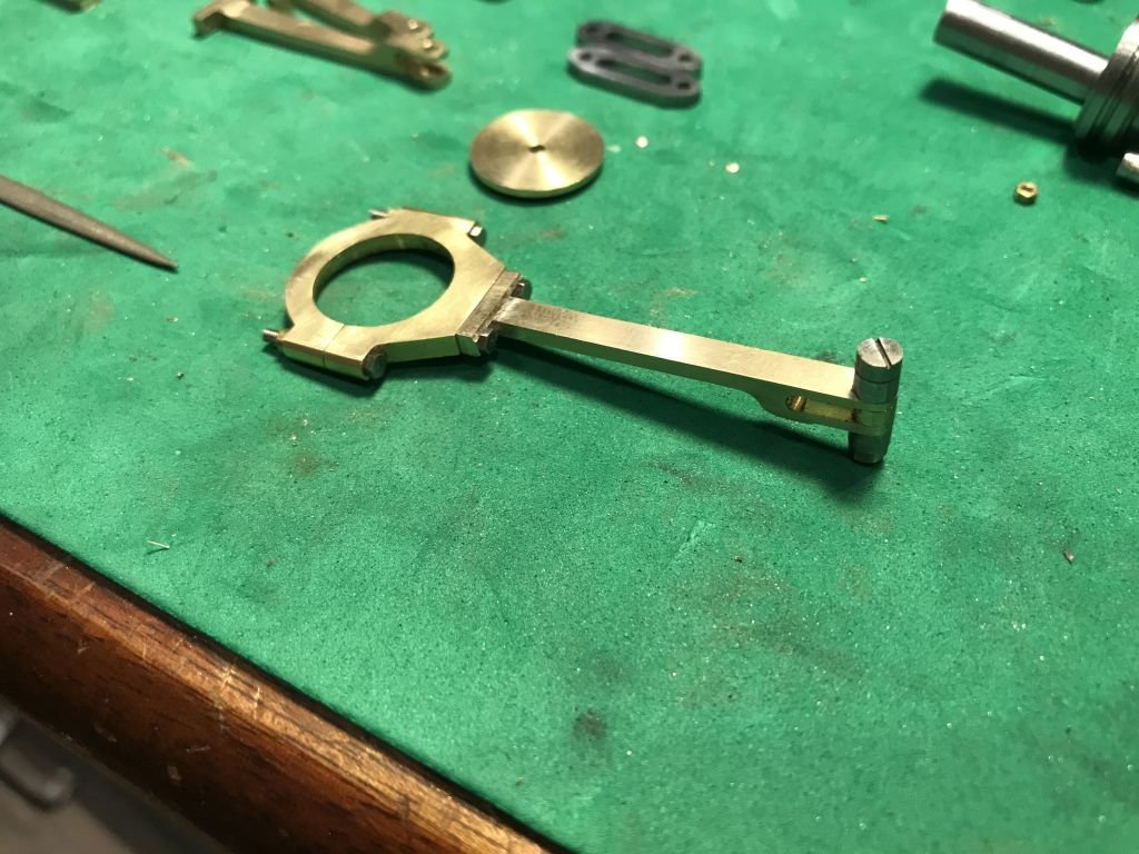
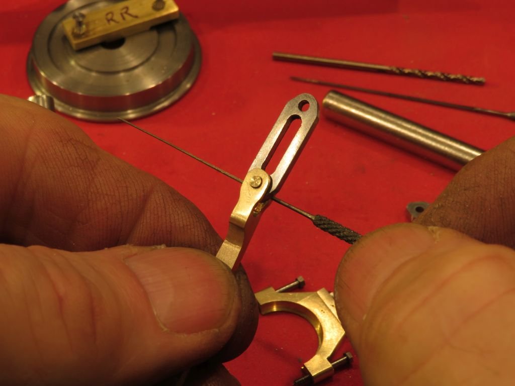
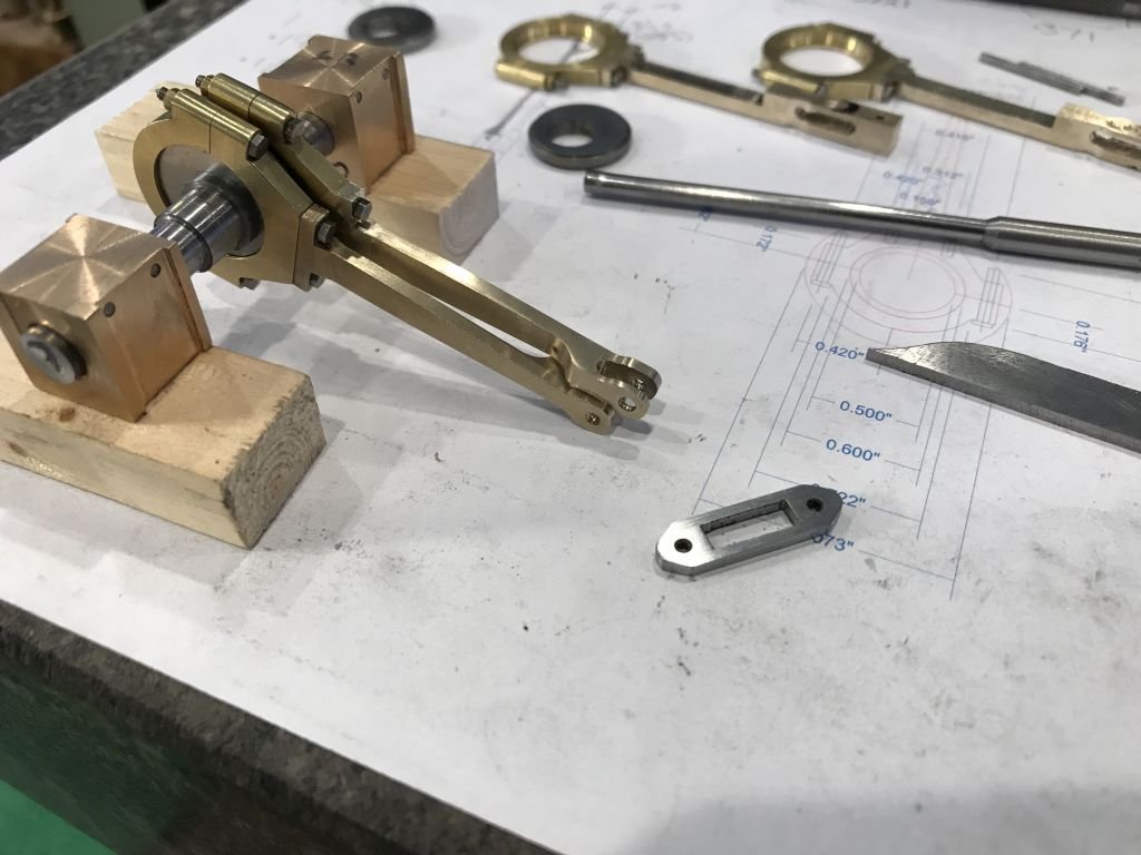
Second set is done. The ends were cut off with the jewelers saw, now on the the radius rods and the weight shaft and lifting arms. the pins are proxy keepers waiting for the final ones that will need tiny taper pins somewhere between "60 and #70 Drill before using the taper reamer. With the new straight links cut from some .075 inch thick steel I have increased the width of the new links by .010" and narrowed the slot from .125" to .098 to give it a bit more meat so to speak. the new link is in the forward set, I just have to finish filing up the second one to replace the rear one. Michael
- 96 replies
-
- 10
-
-
Hi Danny, very nice and yes the intricacy of your model is amazing. It might be possible with a bit of trickery to make the model work on air. A better option that firing her up! Michael
-
Just catching up Maury things are coming together nicely. I like the wheel too. Michael
-
Keith, the simple jigs are valuable, and so often we look for the more complex methods before coming back to the simple ones. Michael
-
Pete, that is looking really nice. Michael
-
Gary , Mark and Druxey, thanks for you very kind words. I spent all morning finishing and polishing up the first set. I also made a proper link out of some steel plate that was left over from the frames. I can tell already that this is going to be a challenge to get all this stuff put together in the frames, and get it to actually run smoothly. And with a little rotation of the axle you can see the change in the angle of the straight link. Now that my fingers have had a rest, and I had a nap I can tackle the second set. Michael
- 96 replies
-
- 12
-