
HOLIDAY DONATION DRIVE - SUPPORT MSW - DO YOUR PART TO KEEP THIS GREAT FORUM GOING! (Only 69 donations so far out of 49,000 members - Can we at least get 100? C'mon guys!)
×


michael mott
-
Posts
5,200 -
Joined
-
Last visited
Content Type
Profiles
Forums
Gallery
Events
Everything posted by michael mott
-
 Just catching up Maury things are coming together nicely. I like the wheel too. Michael
 -
Keith, the simple jigs are valuable, and so often we look for the more complex methods before coming back to the simple ones. Michael
-
Pete, that is looking really nice. Michael
-
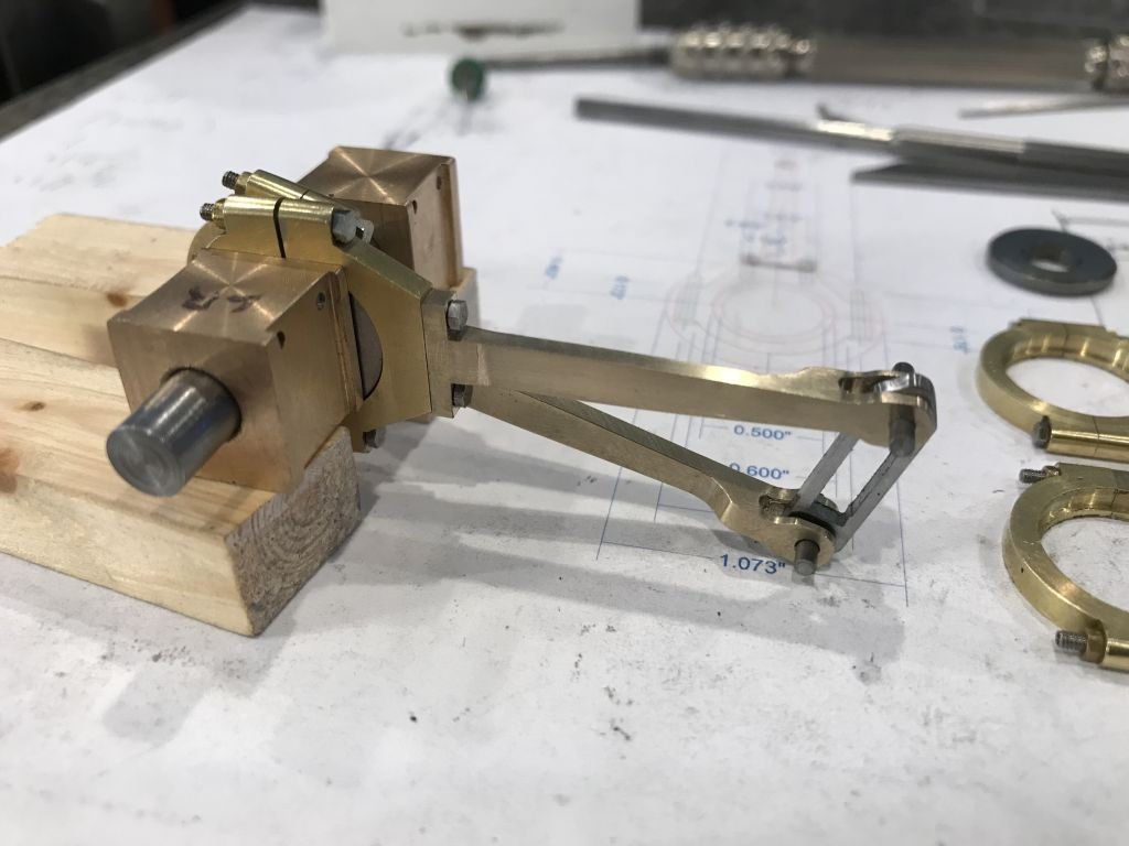
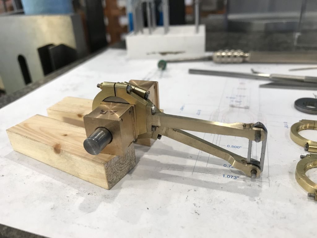
Gary , Mark and Druxey, thanks for you very kind words. I spent all morning finishing and polishing up the first set. I also made a proper link out of some steel plate that was left over from the frames. I can tell already that this is going to be a challenge to get all this stuff put together in the frames, and get it to actually run smoothly. And with a little rotation of the axle you can see the change in the angle of the straight link. Now that my fingers have had a rest, and I had a nap I can tackle the second set. Michael
- 96 replies
-
- 12
-

-
Johann, your work on the blocks is inspirational, they are so beautifully executed. Michael
-
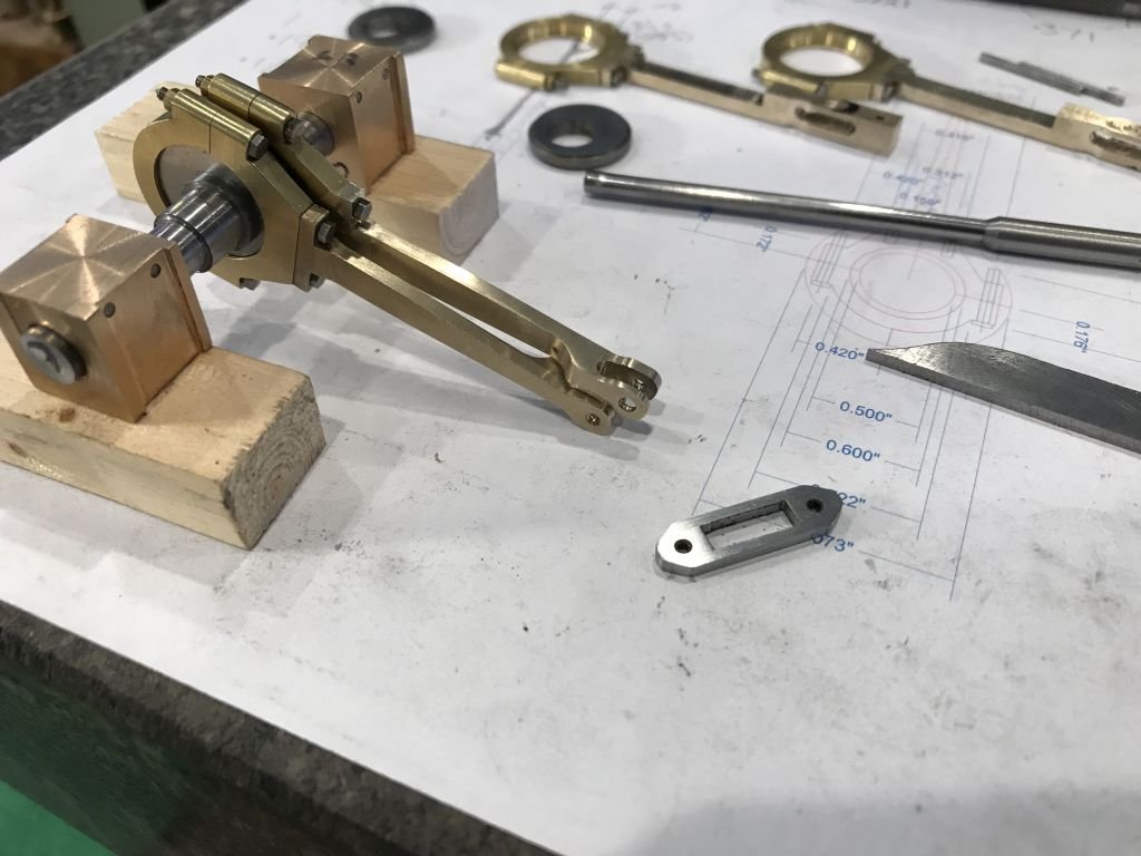
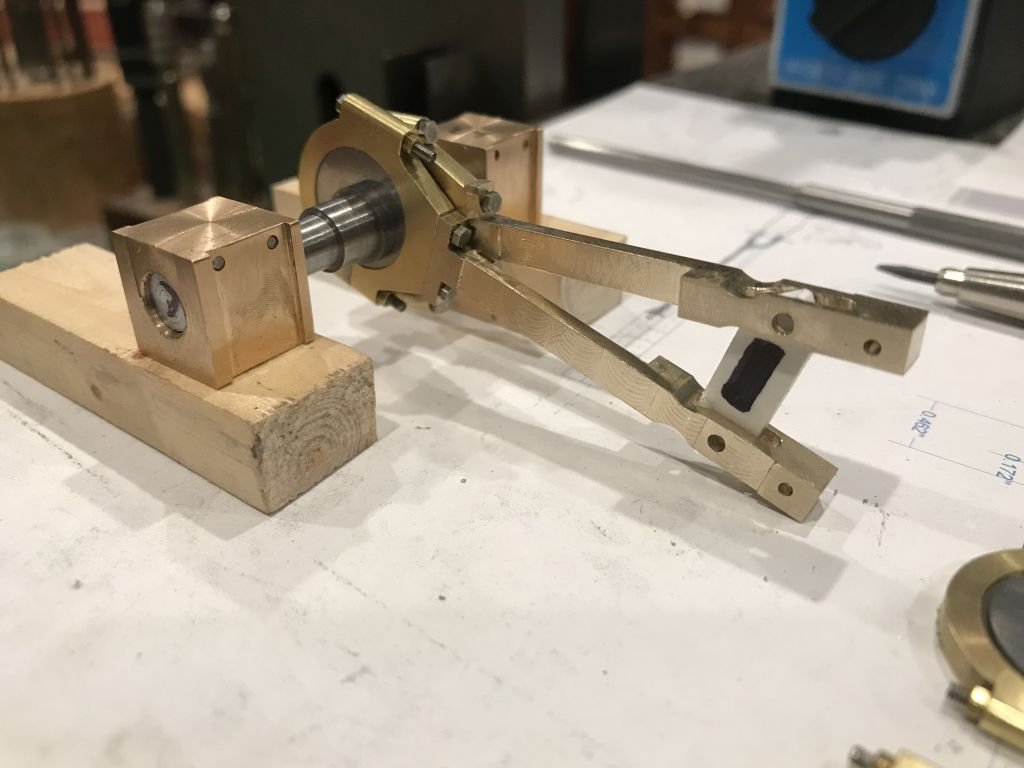
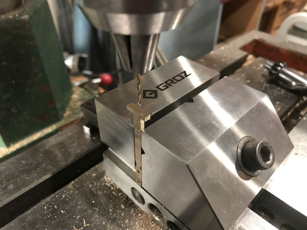
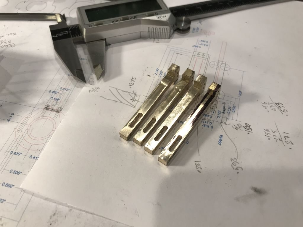
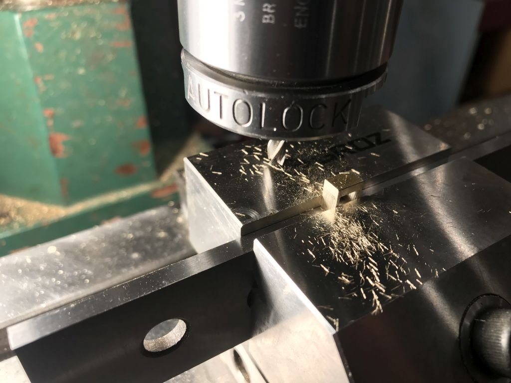
A quick update I have almost finished the eccentric rods. I cut up some brass stair nosing that I acquired some time ago, in retrospect I would have been better off machining these arms from some hard brass bar stock. This material although cast was not easy to machine. After squaring the material up I drilled reference holes and then milled the slot which will become an open fork. but the enclosed slot is easier to machine. After a lot of fiddly milling the arms are ready for some final shaping. First a test fit to see that I am on the right track. And a test fitting on the eccentric discs, the white styrene is a test guide for the straight Allen Gear. That's all for now. Michael
- 96 replies
-
- 12
-
-
Keith I was thinking that the fine sanding dust would be that in situ from the wood itself. what if you were able to use a fine brushful of polyutrethane as the binder for the sanding dust? Just an Idea. Michael
-
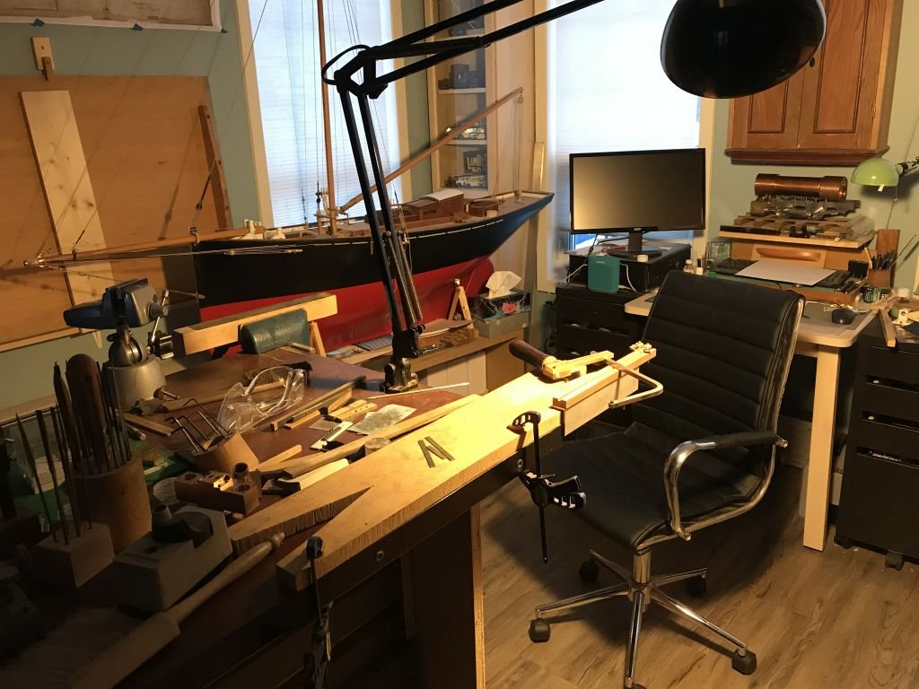
That is why I have a drafting board in the workshop. Every once in a while one just needs to drag a pencil across some velum, the sound alone is music to ones ears! Michael
-
Hello Keith, Catching up again. Super solution on the eye-bolts. Nice form tool! I have files that one away for future reference. I have been thinking about the repairs to the winch holes. Is it possible to scrape away a shallow hollow down to the wood surface and then blend the patch with some fine sanding dust then rebuild the polyurethane with some light layers with a soft brush. The only reason that I suggest this is because of the success that I had with the gouge on the side of the Albertic. I would be happy to send you the little miniature drywall sander that I used to polish off the paint. And that production run of winches looked wonderful. Michael
-
Gary, Just catching up, the details as everyone has already mentioned are superb. Michael
-
Hi Mark great to see that you are building a new ship, I must admit I like this method more than the way you are building the other ship. Michael
-
Nice to see that you are still getting things shipshape on the cutter Rob. Michael
- 1,208 replies
-
- 2
-
-
- great republic
- clipper
- (and 1 more)
-
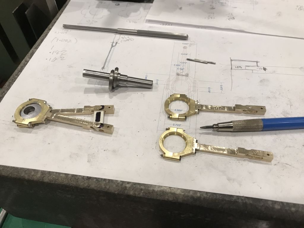
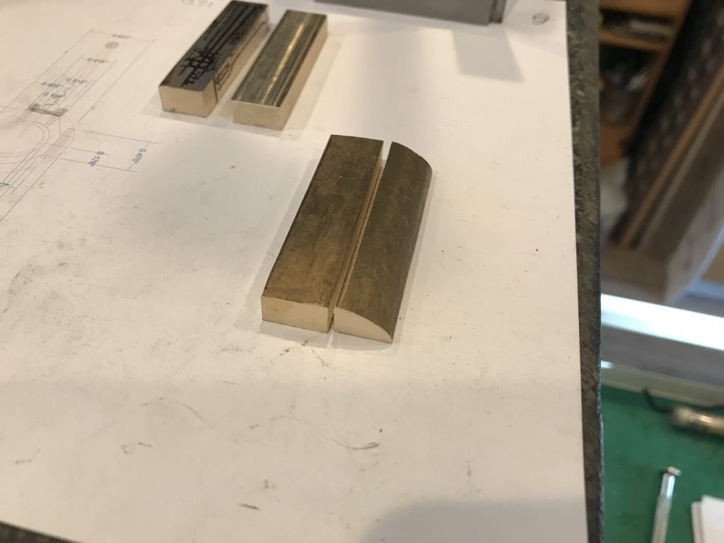
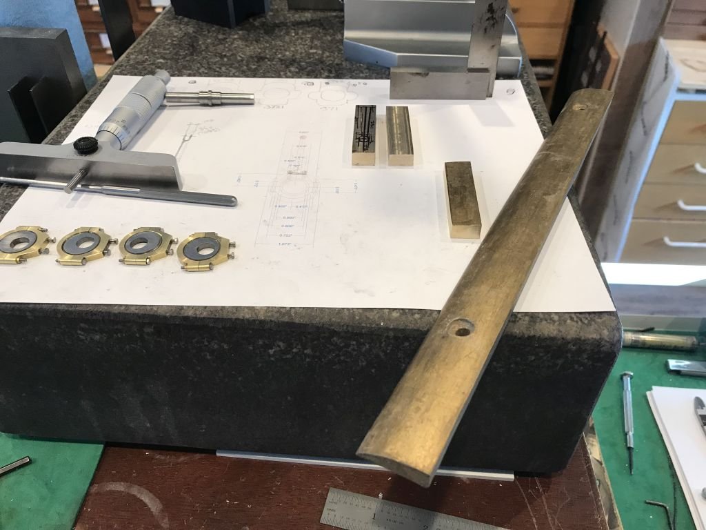
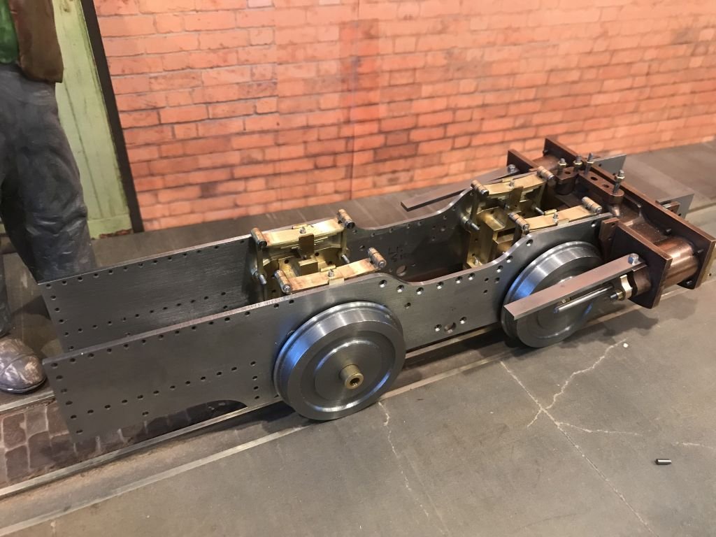
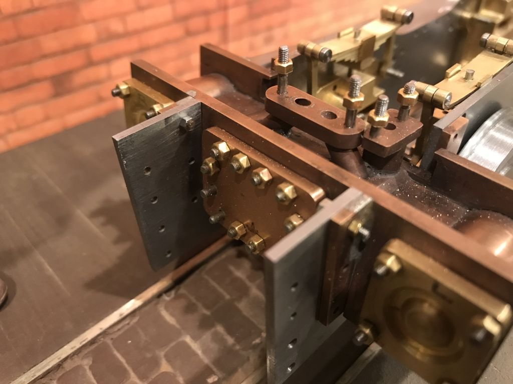
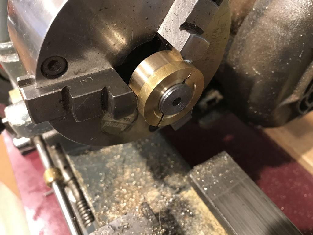
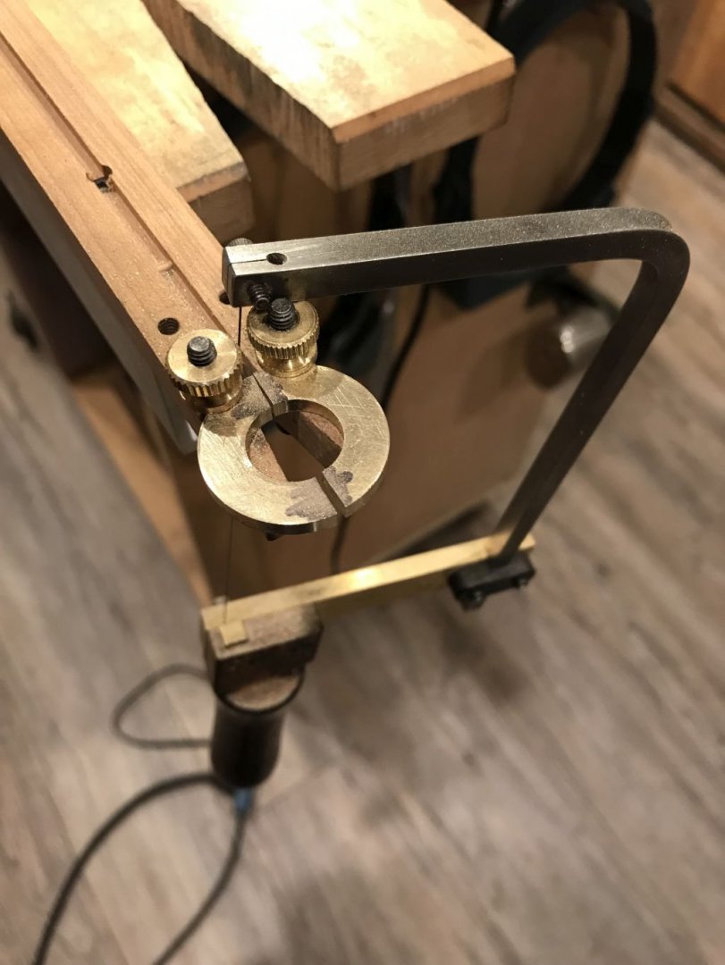
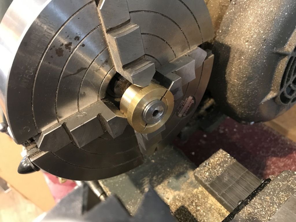
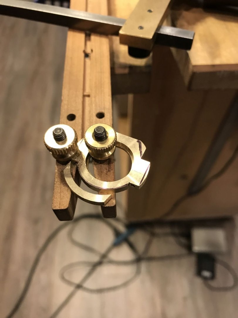
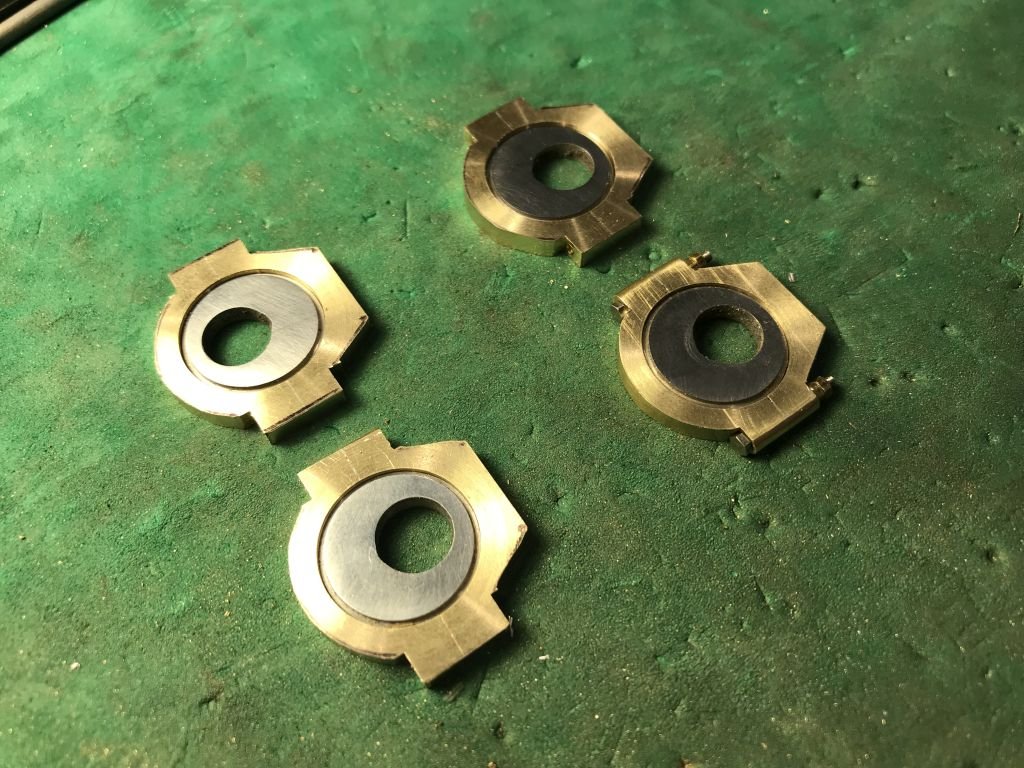
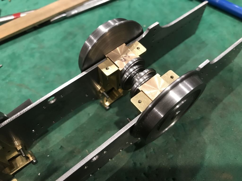
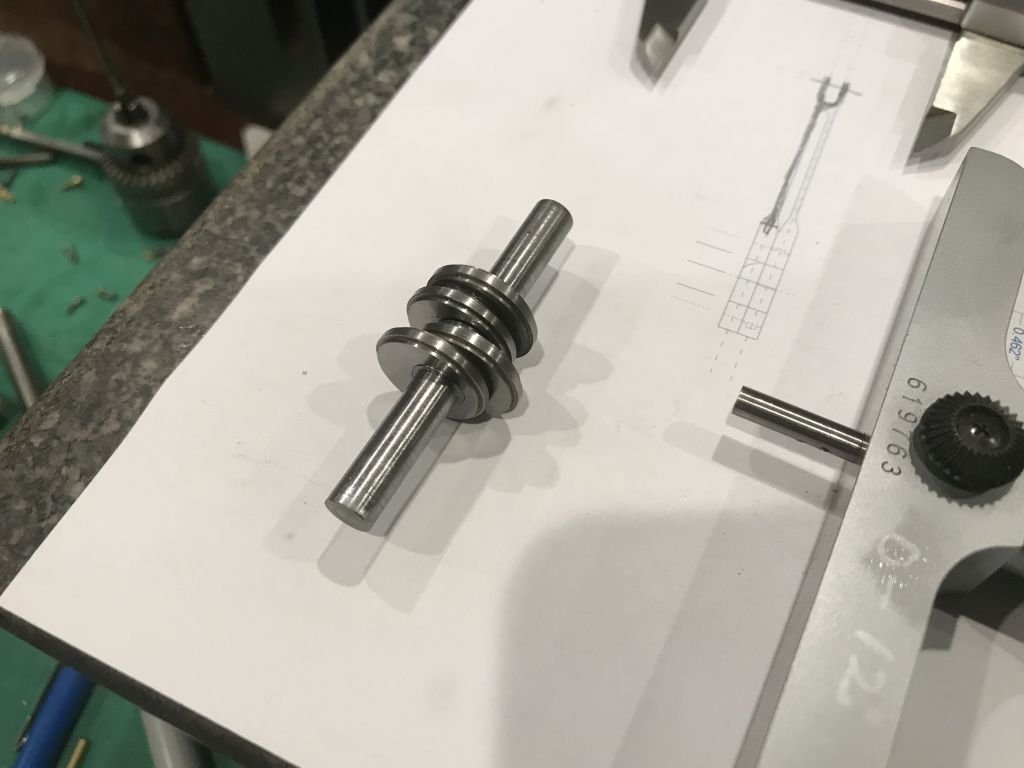
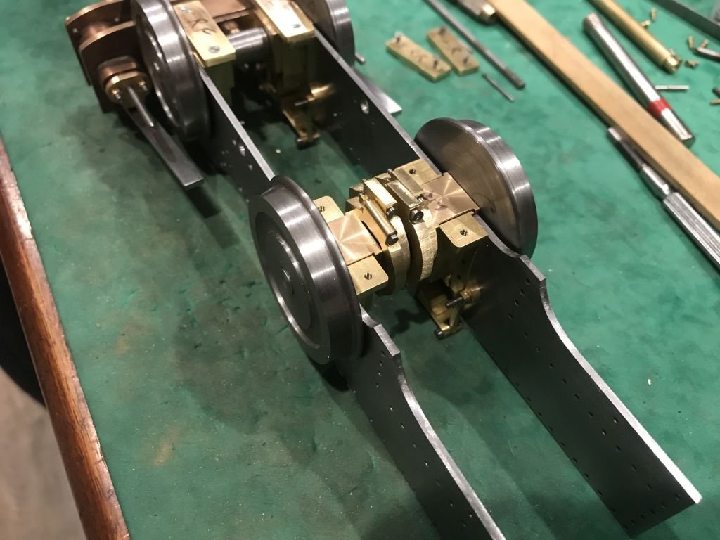
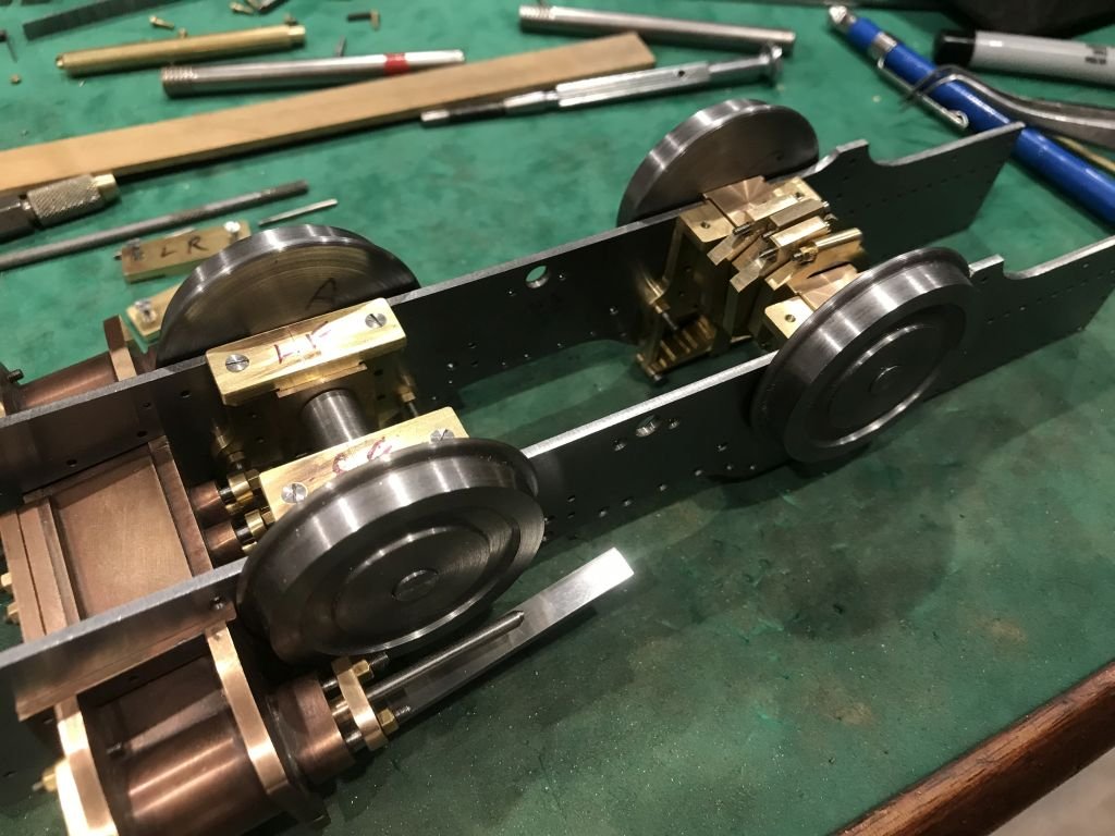
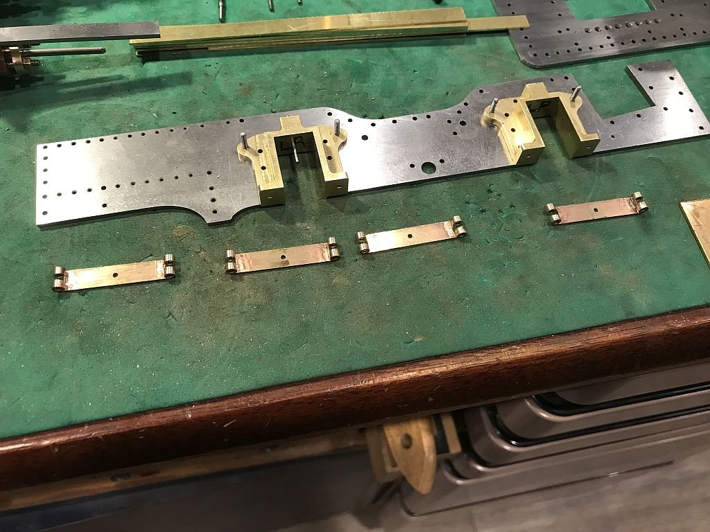
I Have been whittling away at bit and pieces finished the springs. Then a sketch of the axle and the eccentric sets The saddles for the springs was cut from a solid piece that was first milled to create the opening for the leaves of the springs then it was cut into 4 with the jewelers saw. The saddles were then finished off on the mill. I had to make a few 0x80 stainless bolts along the way. to bolt the cylinder assembly to the frames. Then started on the keepers for the axles. Then the eccentrics which are turned out of some 3/4" mild steel. The bottom ends of the 4 eccentric rods were made from some bronze discs that were then cut in half with the jewelers saw. Then cleaned up and soldered back together to be shaped and drilled for the 0x80 stainless bolts to hold the 2 halves together later after all the shaping. they will then be un-soldered The steel eccentric discs were bored out in the waste chuck to the final size of 5/16 which was offset .087 to give a throw on the eccentrics of .175 A little bit of dry fitting to check that the clearances will work The discs will be keyed to the axle so I will need to make some jigs to quarter both the sets of eccentrics and then the wheels. I must say it seems to be getting rather full in-between the bearings, which are actually sprung with some small springs wound up from some .023" music wire. That brings things up to date. Just in case you were wondering, the Bristol cutter is waiting patiently within easy reach, I have not forgotten about it. Michael
- 96 replies
-
- 15
-
-
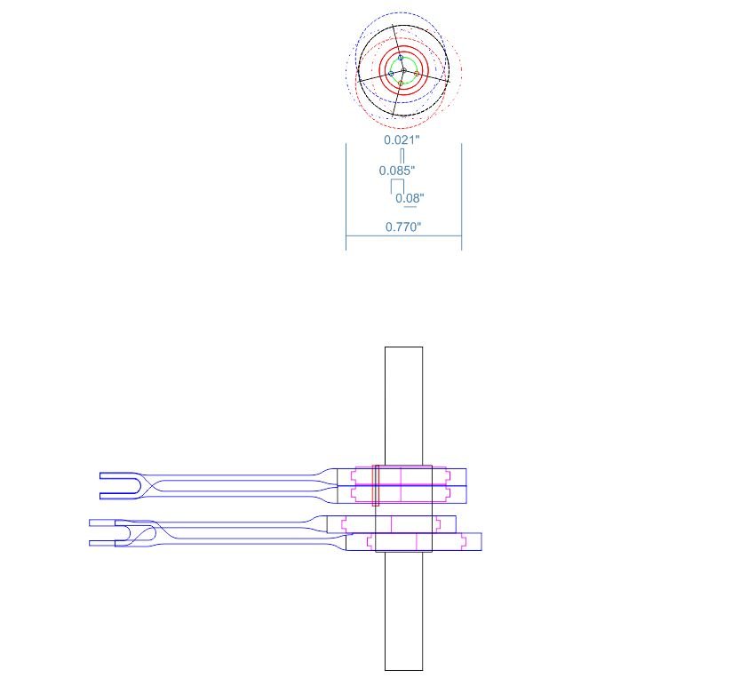
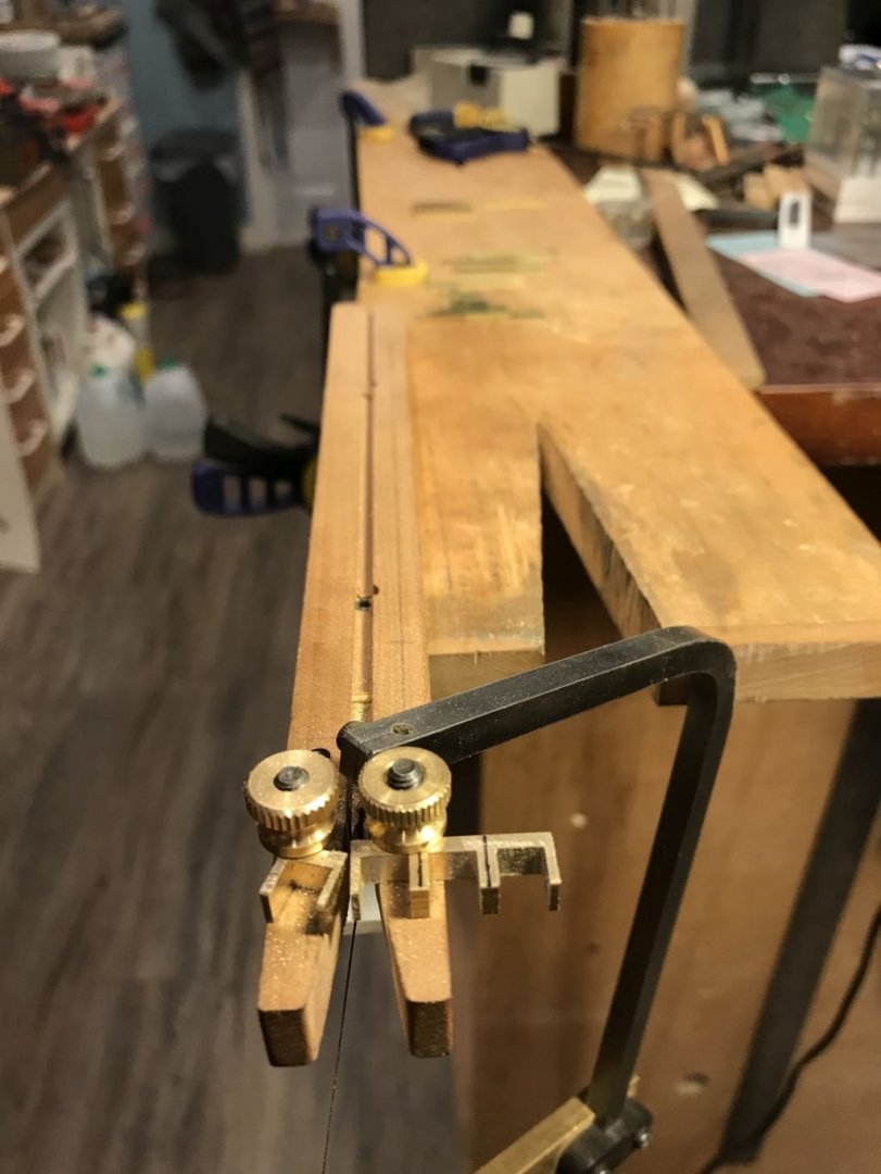
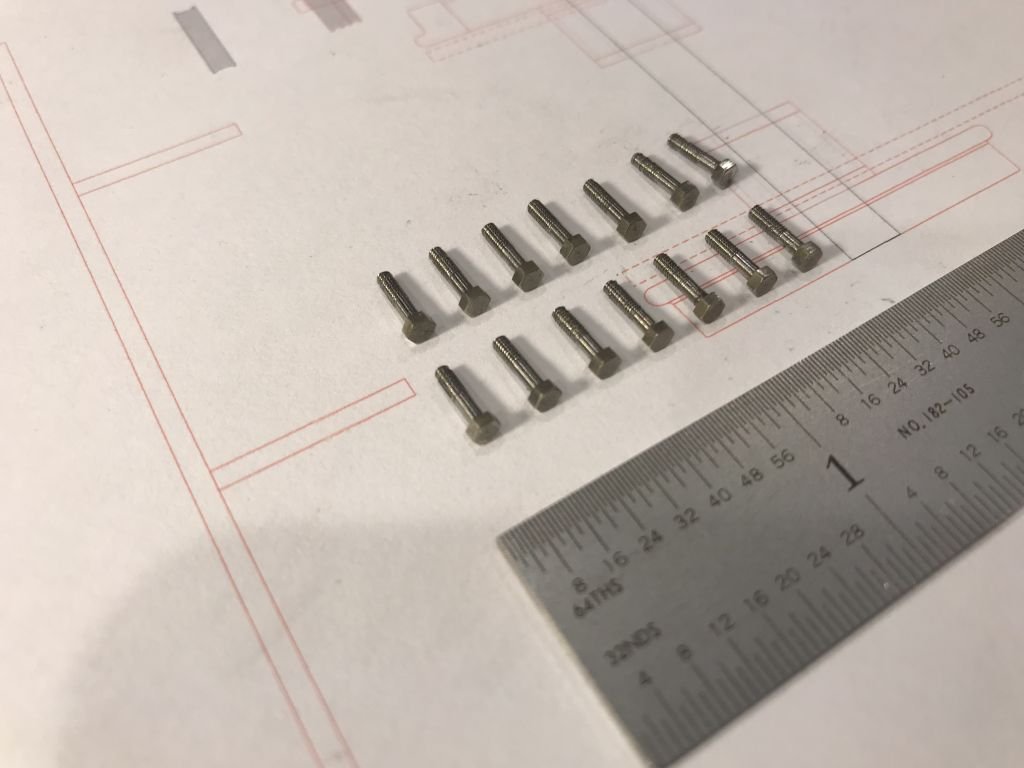
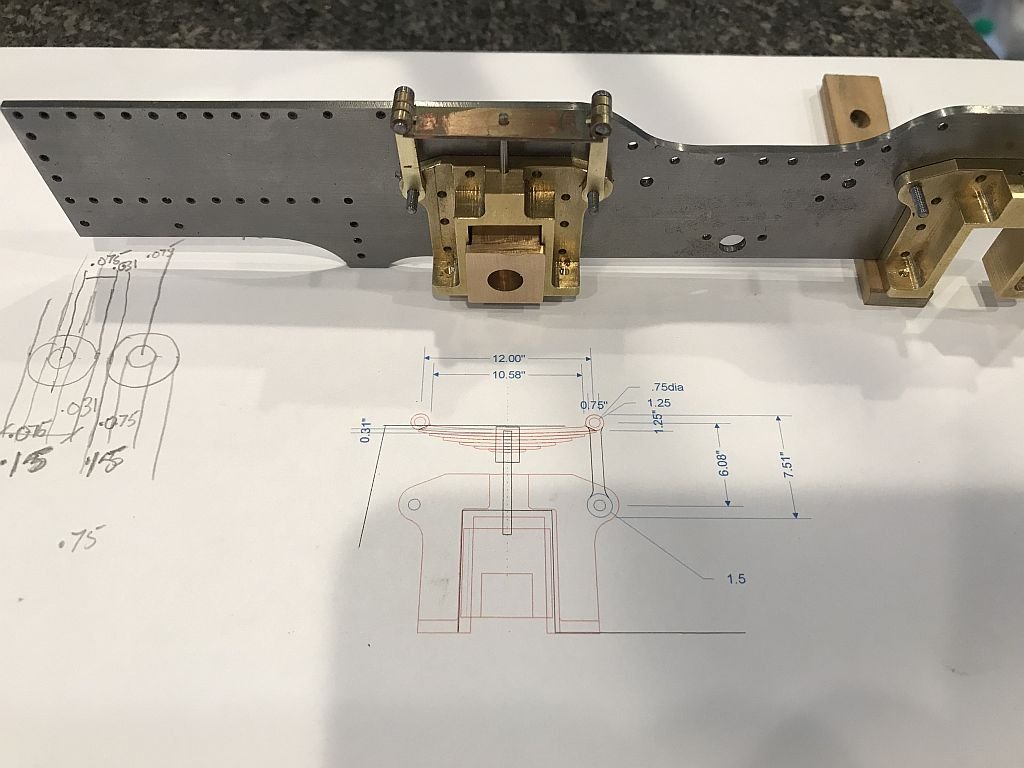
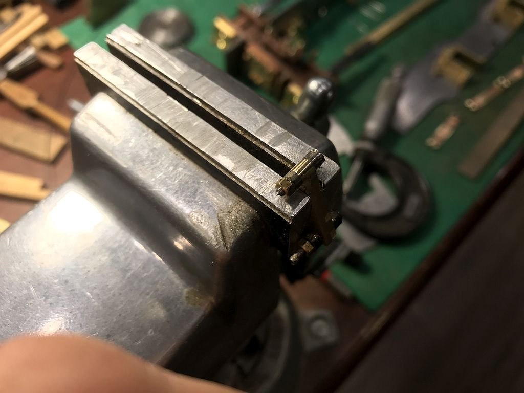
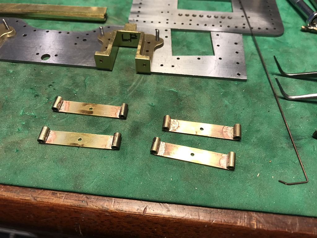
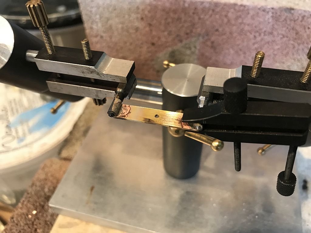
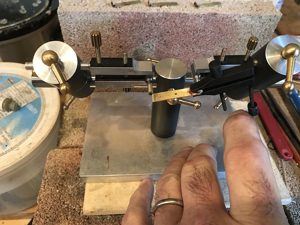
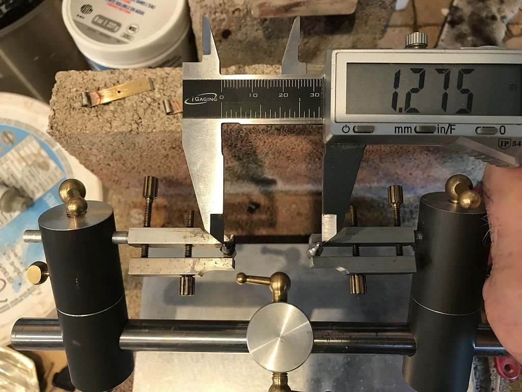
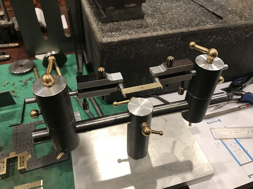
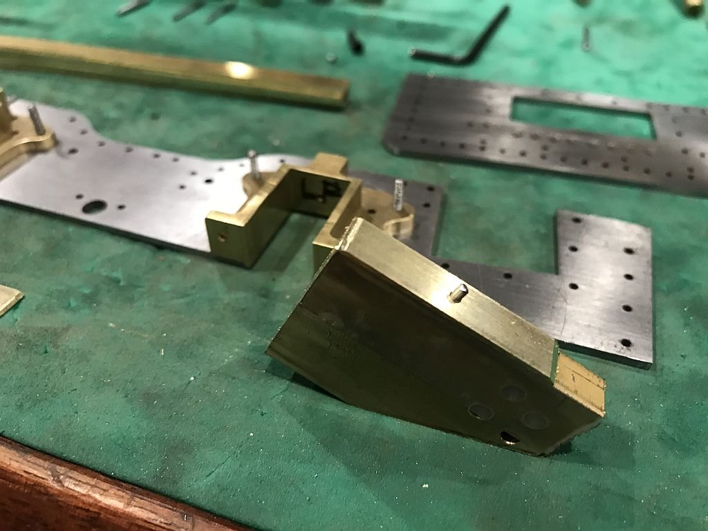
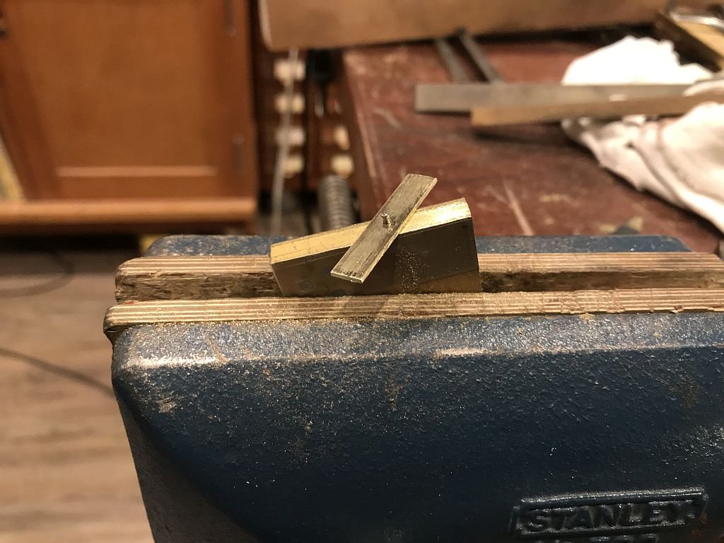
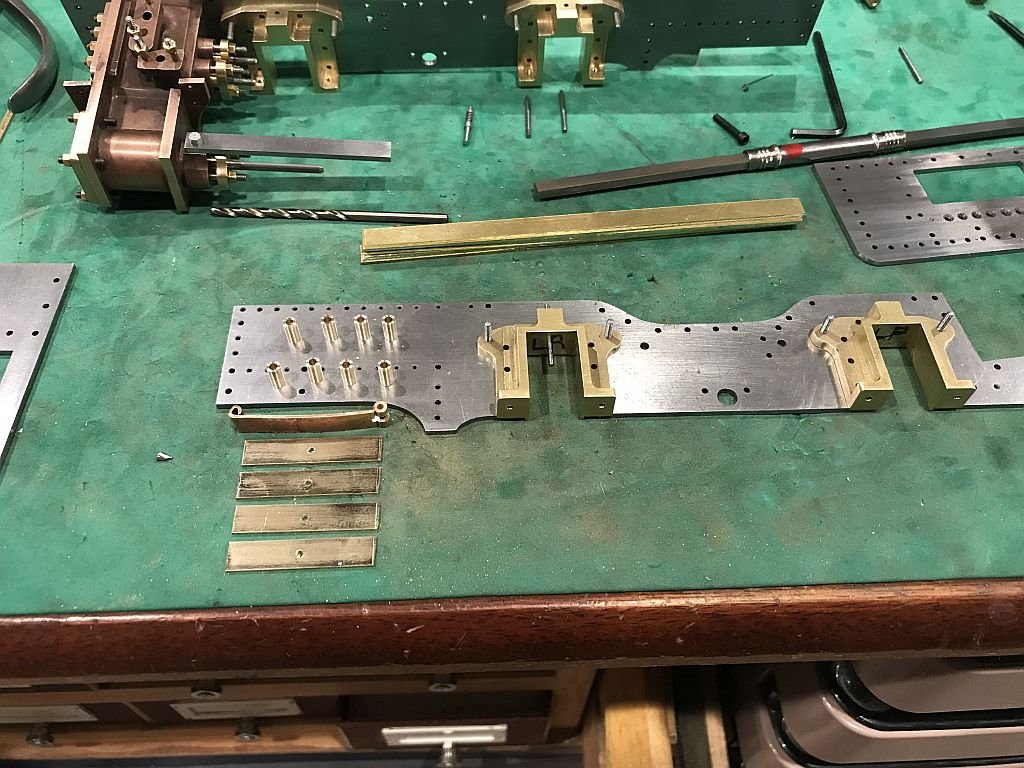
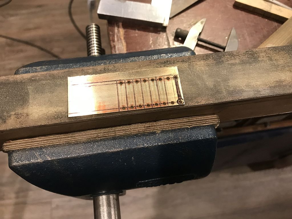
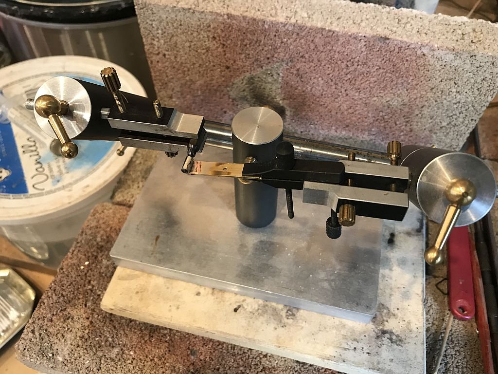
Progress on the springs which need to be in place before the axles and therefore the eccentrics. New spring hanger screws were fabricated and the holes in the hornblocks drilled for the spring rod and the keeper plate on the bottom. the top portion of the springs was more difficult to make than I had originally considered. I tried bending the loops at the ends first and this was not going to work, so the only other ways are to machine from a solid piece or assemble three parts. I chose to assemble the three parts. first part is the plate with the angles at each end for the machined tubes with the correct hole size and outside diameter. the plates were cut to length and the .055" hole drilled Next a jig was developed that could be used to ensure that both ends were the same length from the hole and that the bevel angle could be machined. Next using my accurate adjustable third hand which allows me to set up parts for gluing or soldering very precisely was used to set the tube guides to the correct distances to ensure that all the parts would fit as planned. Then using a second small toolmakers clamp I silver soldered one end using the medium paste silver solder that comes in a syringe. Once all 4 had the tube set on the one end I set up the tube pins to the exact dimension that they needed to be apart 1.2" which equals 12 inches at 1/10 scale. because the pin diameters are .075" the extra distance was added .0375" to each pin so the vernier needed to read 1.275" Using the small toolmakers clamp as a counterweight which caused the end that next needed to be soldered to contact the other tube accurately it was fluxed with the paste silver solder and soldered. Next I added the slots and spring hangers. These were set up in the mill and a 1/16th end mill was used to make the sluts at each end. Next the hangers were cut from some .075" brass sheet after the holes were drilled and the individual hangers were cut out they were assembled in pairs to shape. A couple of filing buttons were fabricated with the 2 different diameters on set .150" and one set .125" the filing buttons were made from drill rod or silver steel as it is sometimes called. The next step was to turn up a couple of .075" pins to connect the hangers to the springs. Now that the sequence is sorted there are only 3 more sets of hangers to file. after that I will be making the rest of the spring leaves which are .025' thick thinner than the top one which is .031 They will of course need to be slightly curved as will the top one. Because I am not going to actually make these springs fully functional I will be adding a tiny micro compression spring which will not be seen to give the axles a small bit of spring suspension. Michael
- 96 replies
-
- 10
-
-
Now that I understand a little better, I agree with Steve, as an alternative to shellac you could use a tiny drop of ochre coloured humbrol or equivalent paint. a dab of lacquer thinner would dissolve the bond. Michael
-
Hi Peter, yes it is me I have this dual personality that flips from boat to narrow gauge railways, which narrow gauge forums are you familiar with? Nice that your grandson is keen to do serious "toy" work. Michael
-
Best type of micro drill bits for metal
michael mott replied to BETAQDAVE's topic in Metal Work, Soldering and Metal Fittings
Over the years I have found this method to be the most reliable but it is most important to have the piece being drilled securely held so that it does not move. Michael -
Drilling 2mm Brass Rod
michael mott replied to spill50's topic in Metal Work, Soldering and Metal Fittings
Do you have any pin vices that will hold the 2mm rod? the pin vice can be held in a larger vice that needs to be clamped to the drill press table so that the vice is secure and wont move. also in your large drill press it would be useful to have a smaller pin chuck to hold the small drill bit, unless of course it is one of those bits with a larger shank either 1/8th or 3/32. Whatever method you choose you will need to spend a bit of time setting up and testing your set up. Michael -
Lovely that you are able to work on a joint project with your grandson Peter, The look of concentration on Brandon brought a smile to my face. Michael
-
Keith I regularly use the jewelers saw to cut small stuff off on the lathe nice solution for the tiny parts, what if any lubrication did you use? Michael
-
Thanks for your answer Danny. Michael
-
Vaddoc if you silver soldered the shackles you could fill the holes with soft solder then re-drill the holes which would also ensure that they are in line. Michael

