HOLIDAY DONATION DRIVE - SUPPORT MSW - DO YOUR PART TO KEEP THIS GREAT FORUM GOING! (Only 13 donations so far - C'mon guys!)
×


michael mott
-
Posts
5,197 -
Joined
-
Last visited
Content Type
Profiles
Forums
Gallery
Events
Everything posted by michael mott
-
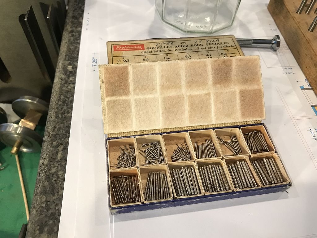
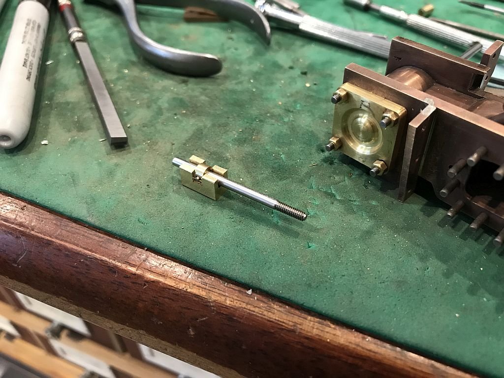
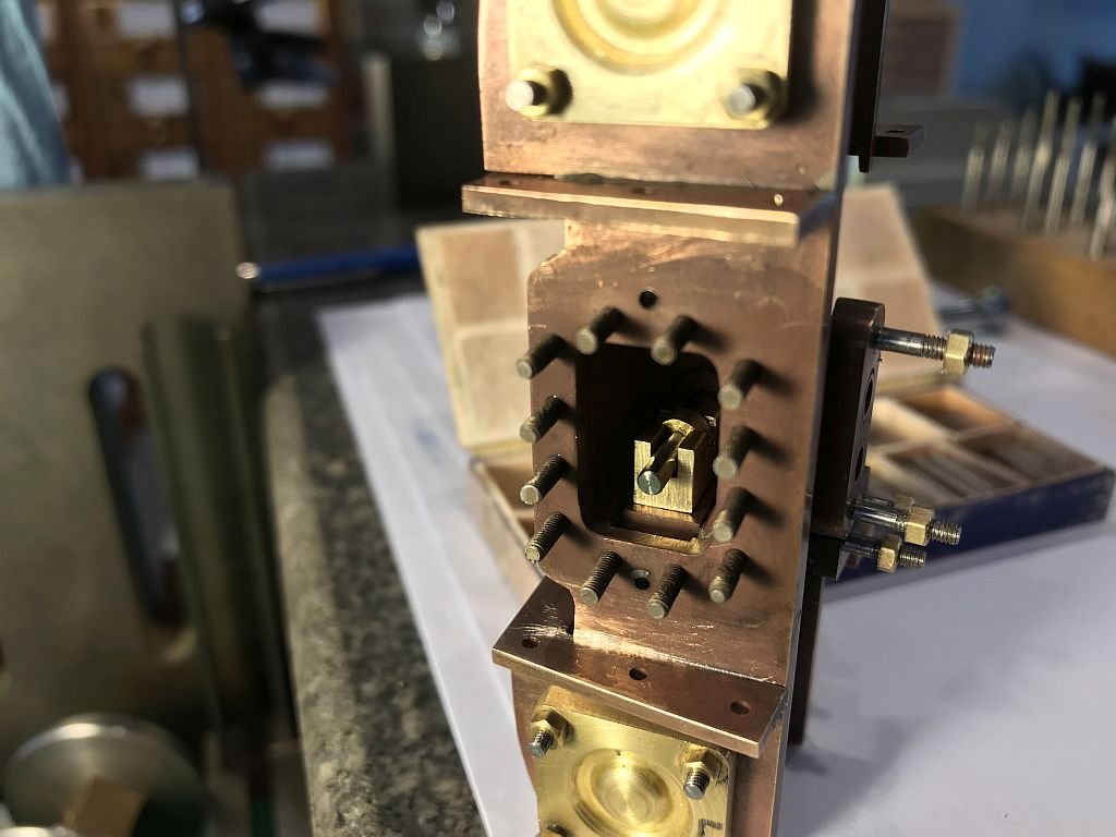
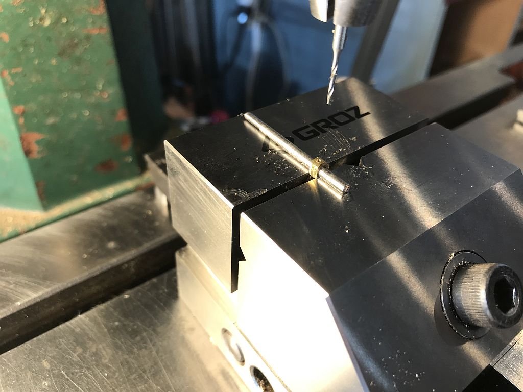
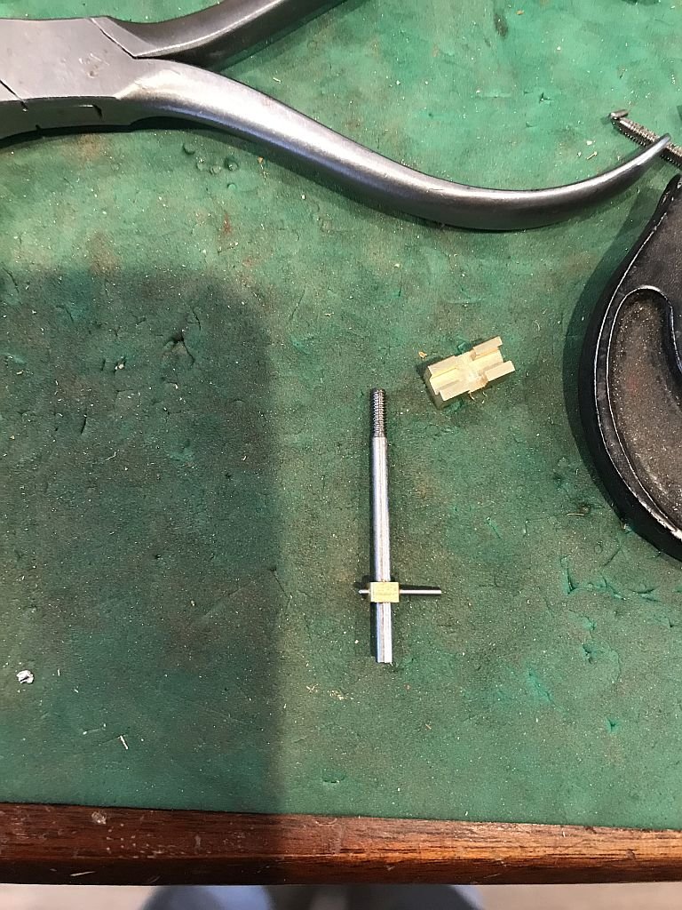
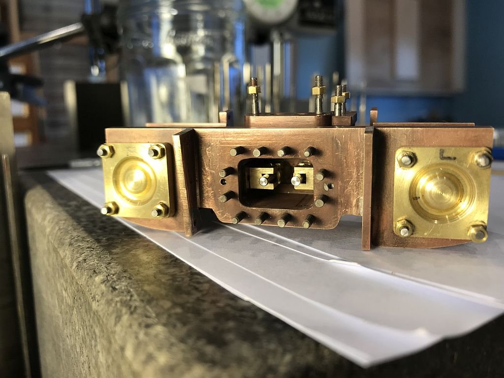
 I have been working on the D valves and the small keeper that fits into the cross slot so that the valve gets pulled and pushed back and forth in the valve steam chamber. First the keeper had to be drilled and reamed for a taper pin these pins are used in clockwork and are really handy. This box of pins I must have been using for the last 30 years, I don't use a lot but they work really well in some applications. There is a set of taper pin reamers that are specially made for these pins and The reamers are also good for opening up holes a little when needed. The next picture shows the keeper glued to the valve shaft with some loctite then clamped for drilling the hole for the pin. The next shot shows the taper pin reamer being worked through the assembly. After the pin is seated with a light tap of the clock-makers hammer Then the long ends are snipped off leaving enough proud so that the pin can be remove if needed for repairs down the road. The valve shaft and the D valve are now ready to be set into the steam chamber. The first valve fitted The next picture shows both valves set into the chamber,before closing it up. and finally the slide bars are now cut to length and width ready for the cross slide. The space between the frames feels small enough the I am guessing that I will need to make some special tools for getting to some of the parts. Sort of like the articulated right angled whatsit wrenches that the auto supply folk charge an arm and a leg for in order to change a spark plug that is buried next to the firewall. Michael
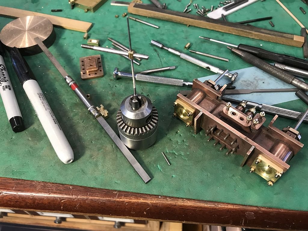
- 96 replies
-
- 13
-

-
More fine metalwork to feat the eyes on. Michael
-
Thanks for the update Rob, great job on the renovation. those look like serious binnies, probably easier to look through than a telescope. Michael
- 1,208 replies
-
- 2
-
-
- great republic
- clipper
- (and 1 more)
-
Andy, Yes your analysis is correct and the way that this little loco was working in the Horwich works was slow and a lot of forwards and backwards basically the "fork lift" of the day (1887)There was not a great deal of need for speed but a lot of stopping and starting. This was a very small locomotive only 7 foot 4 inches long. Jan Thanks for stopping by, I'm in model engineering mode at the moment this will of course wane and then I will be back at the cutter. Michael
-
Exquisite work on the oarlocks Steve. Michael
-
Keith, everything is simple - I don’t have a square bar of suitable section size. I have also found that round bar is usually harder that square bar regarding the machining quality. What I am trying to say is that often I find the square bare to be less easy to machine than the hard free machining round bar. Beautiful work on the model Valeriy. Michael
-
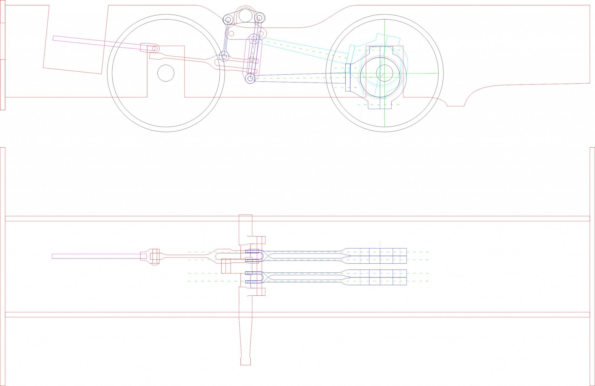
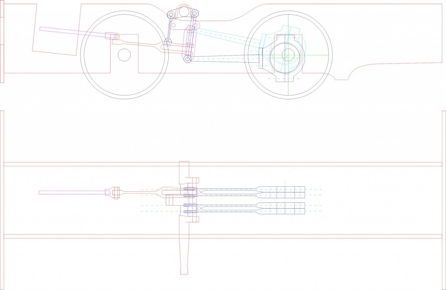
Good evening Andy. The loco uses the Allan straight link valve gear this diagram shows the configuration The link from the valve rod is shown in plan view in the top elevation as the long lifting link lifts the straight link the opposite side drops the link to the valve rod. If this is not clear enough I can post more information. I did manage to make a couple of pistons today I will be using o rings. Michael
-
Hello Gary I just finished going through this build. Such a lot of great detail in small places the compass in the wheelhouse and the hose are just two that stand out as excellent touches, the overall weathering works really well worn but looked after. Superb job. and I also loved the little dioramas in the shadow boxes. Michael
-
Just went through this build Danny, beautiful work! Mike
-
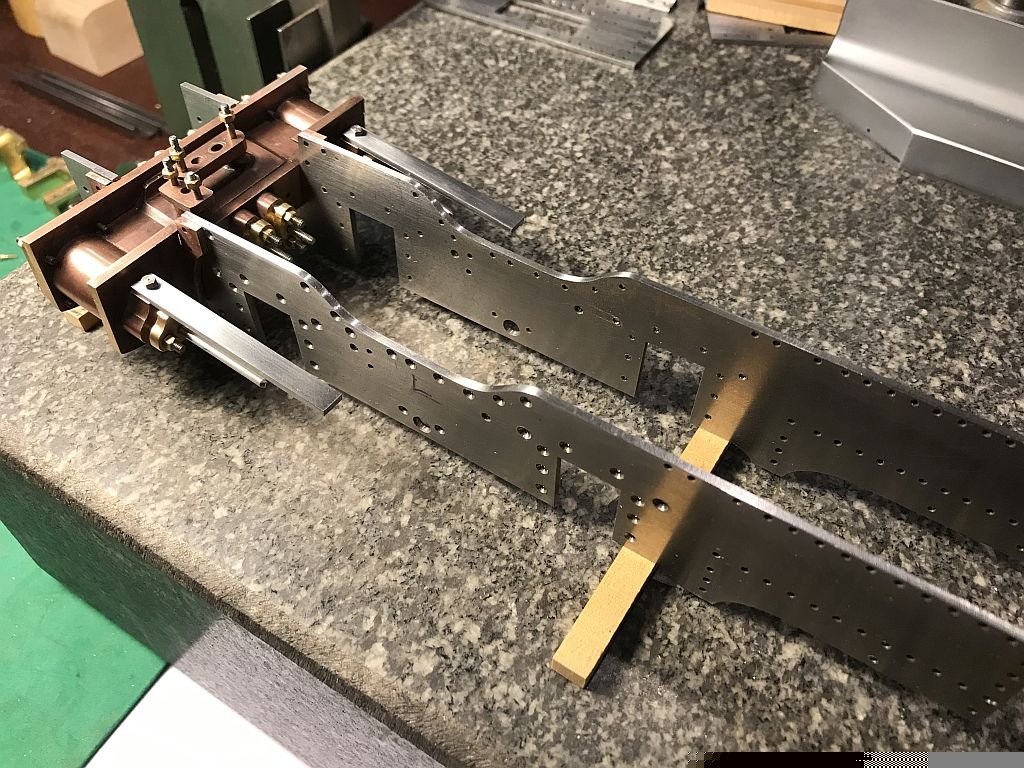
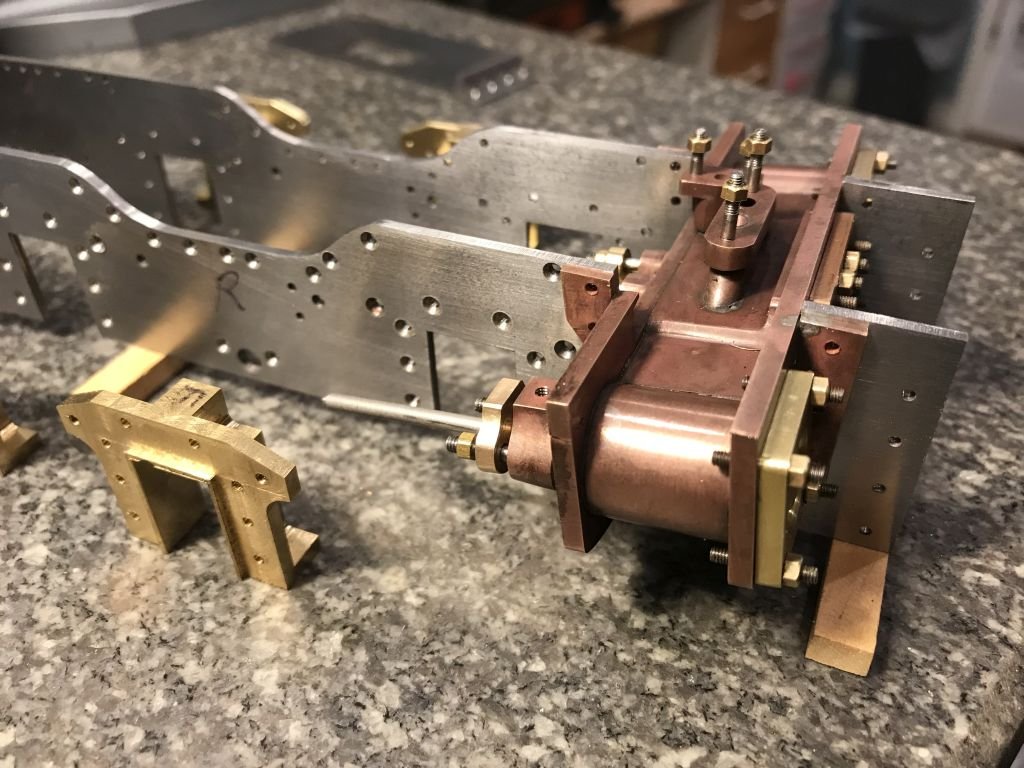
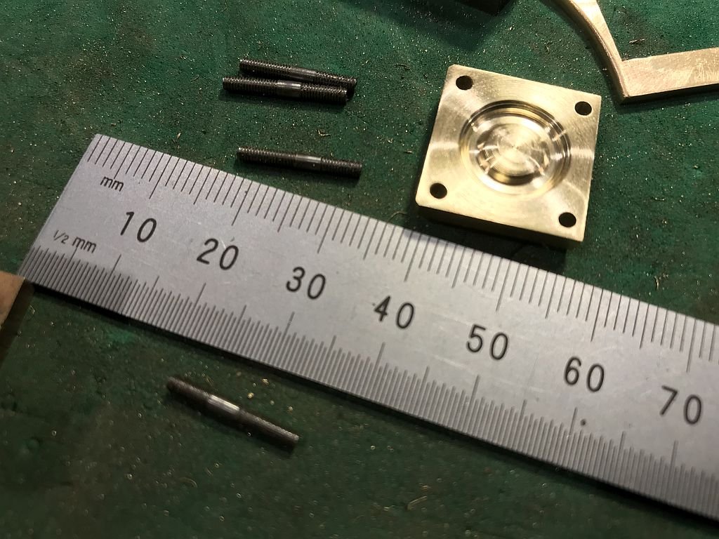
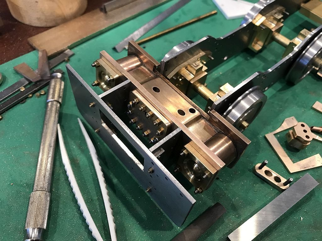
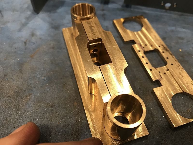
Thank you for all the kind comments. I have now finished putting all the pieces together for the cylinder "casting" I can now re-polish the cylinder bores and make the pistons, and D valves. in order to spot the bold holes for the cylinders I had to take the frames apart and lay the bolting flange next to the opening and spot through from the backside to make sure that the holes lined up. After that was done the flanges were soldered to the block. The first picture show the raw cylinder "casting" set into the raw frames. The coppery color come from the pickle bath and since the cylinders are going to be painted Black I am not going to be concerned about it. The next picture is showing the replacement of the keeper studs with the final ones machined with the unthreaded part in the centre, Next picture shows all of the studs have been replaced with the proper ones. Also while the hornblocks have been taken out and the drawings from NRM (National Railway Museum), have arrived I can finish them off now before replacing them into the frames. Once I finish the pistons and D valves I will be able to test the seals for the assembly. There are still lots of screws and bolts to make. and the whole valve gear is now beginning to loom it's "hydra head" Michael
- 96 replies
-
- 10
-
-
So true, and then when you see a solution by somebody else you think to yourself "why didn't I think of that?" Michael
-
Wow Danny, That is one masterful bit of card work. I think I will stick to metal. I will follow along. Michael
-
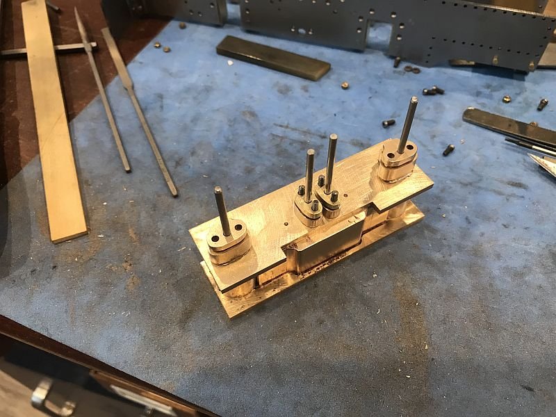
I finished the studs they are a bit fiddly to make but I am getting the hang of it. I have also finished the 2 cylinder covers, I glued them into place with some CA glue in order to spot through for the tap drill, first lining up the hole with the clearance drill then changing to the tap drill after spotting the plate. finally all the studs are set to the main body and the covers fitted. Had to deal with cleaning up the yard from the cutting down of an old Crab apple tree I kept a couple of large chunks to billet up and dry slowly but the rest I gave to my friend who helped me cut the tree down. I was so busy I did not take any pictures. so popped the cylinder set into the chassis for safekeeping till the yard is cleaned up of all the rotten squashed crab apples and the trimmings. That's it for today Michael
- 96 replies
-
- 17
-
-
Keith it is such a pleasure watching how you solve some tricky fabrication issues, nice one on the eyelets. Michael
-
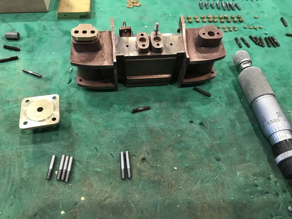
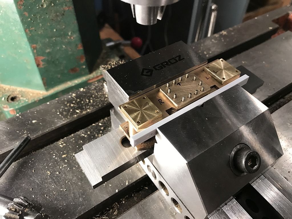
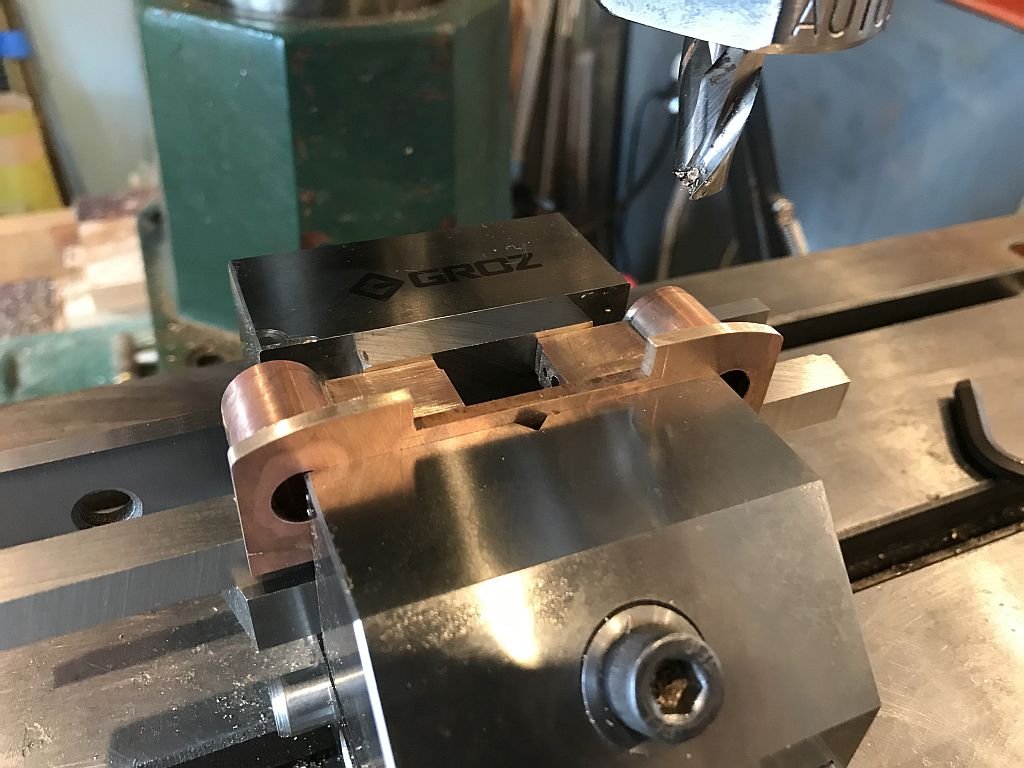
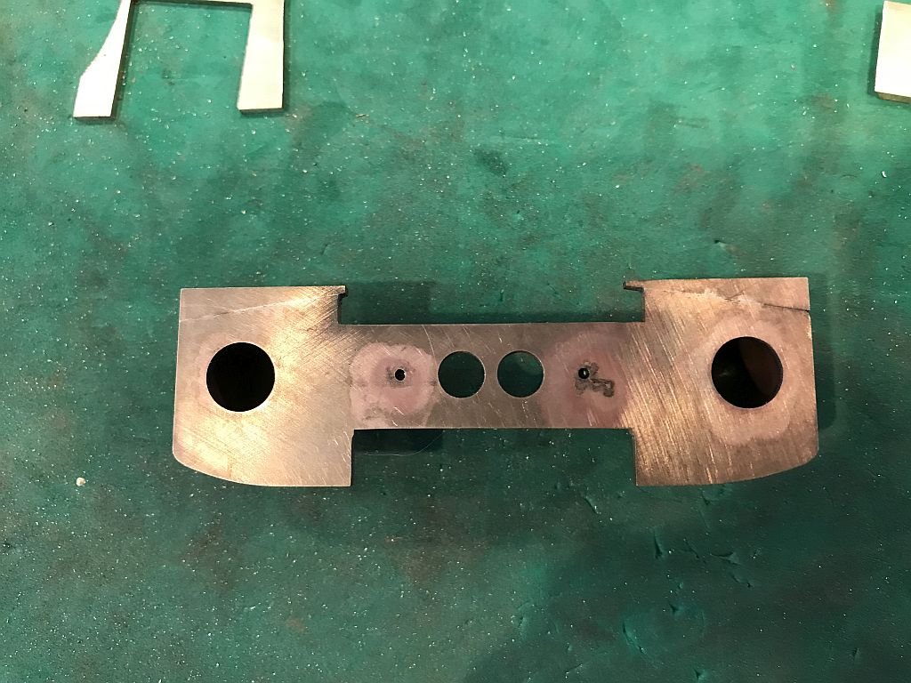
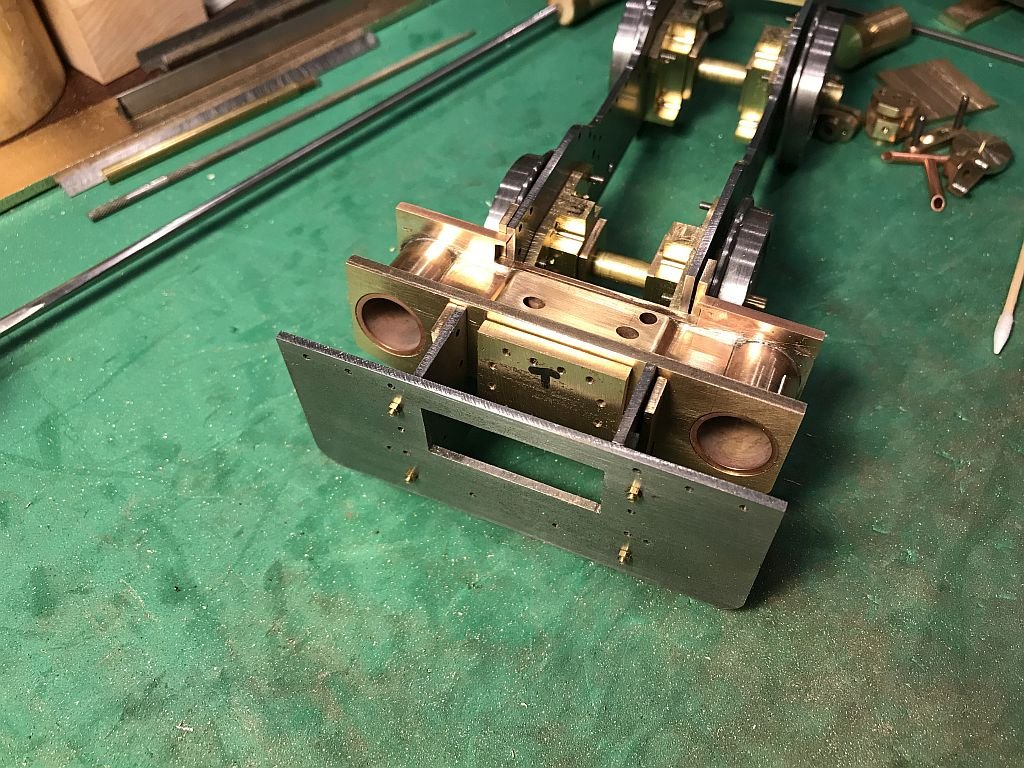
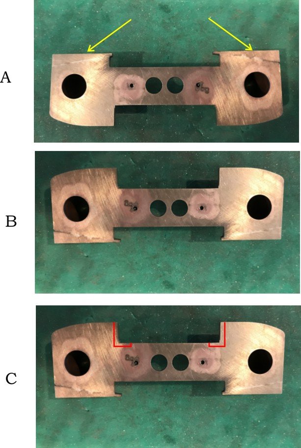
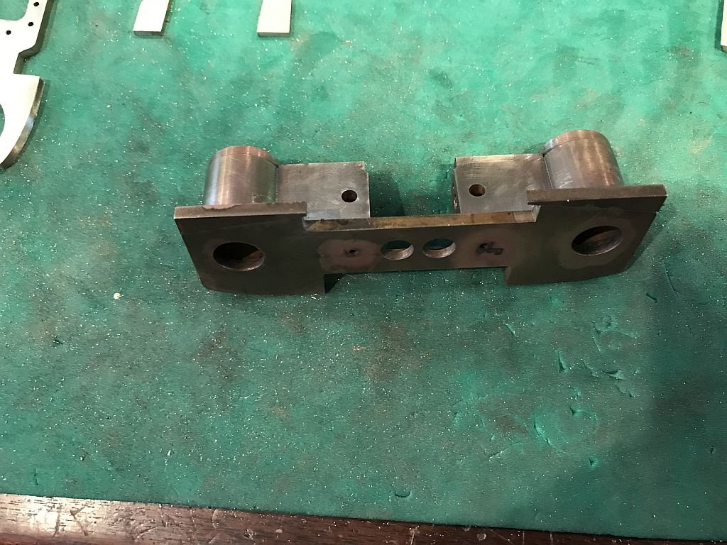
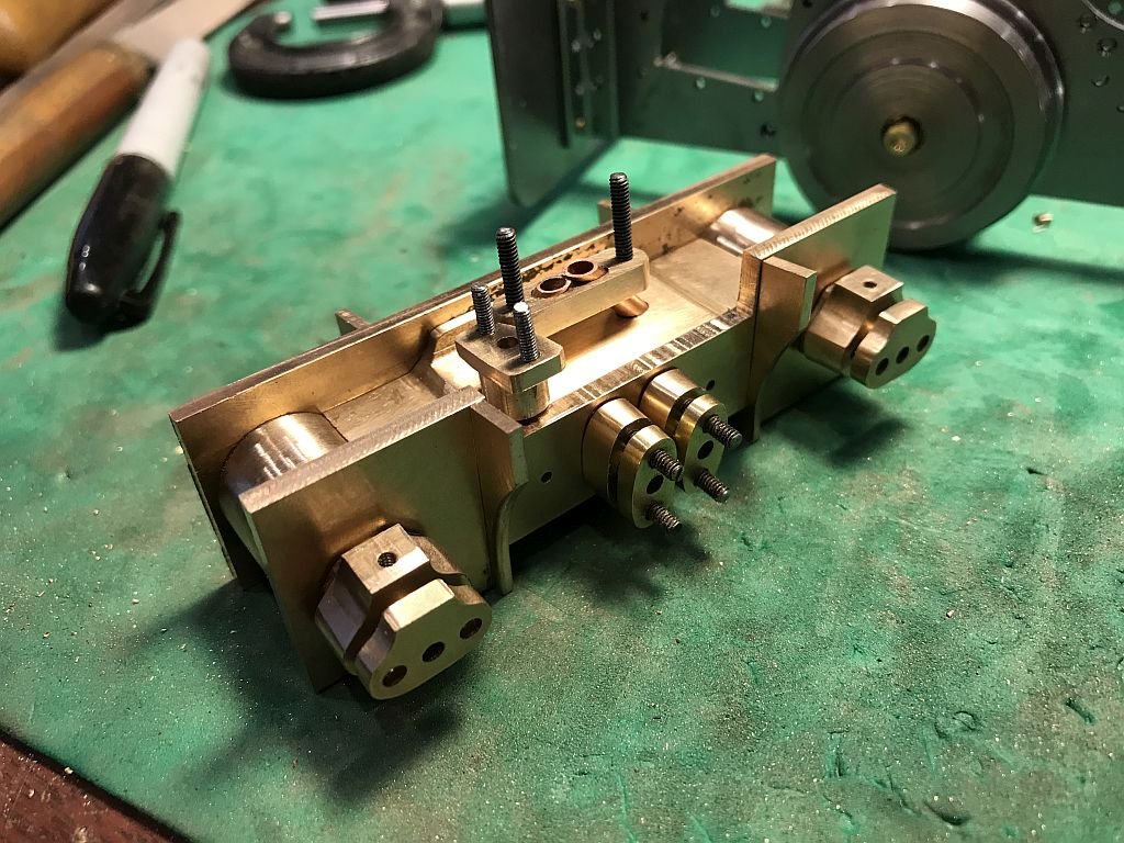
Phil, Kurt, that is very kind of you. The interesting thing is that I also make the most unthinking colossal mistakes occasionally and yesterday was one of those days Because of the nature of this part (cylinders) is complex i have been worried about the assembly procedure and the fact that I need the parts to hold pressure in order for the thing to actually work....I haven't even got to the valve timing yet. So on Monday evening after I had posted my last pictures I went out to the shop to do some shaping of the bottoms of the plates I shaped the bottom curve on the front plate first because I had planned on soldering that first. If you look carefully you can see that there is a couple of wedges of bronze silver soldered to the top of the assembly the inside edges need to be filed down to match the cut out yet, I was really pleased with the fix and had spent about an hour preparing for the next set of elements to be soldered to the block. setting up and soldering this had taken the better part of the morning. The first part was to shape the curve onto the bottom because I had the night before put the curve on the top instead of the bottom. I was annoyed with myself for the silly mistake and so fixed it first thing and because the rest was going to be done with the high temp soft solder I decided to silver solder the wedges on. This next picture shows it more clearly It was close to lunch time and Judy came in and I was showing her how it all fitted together because she wanted to know where it fit on the model as I began putting the rest of the parts together holding ithe assembly to slide the flanges on which hols the plates together I realized I had completely screwed up the next picture shows the problem in A the wedges are highlighted, BUT it is upside down!!! B shows that I had not only filed the new shape on the bottom but then filed off the correct curves and rebuilt it to be square leaving the first error intact. I said a few words loudly that cannot be repeated, and felt absolutely stupid.... how could i have made such a mistake again? Lunch was not spoiled however I was quiet Judy bless her said "you will sort it out" and added "Perhaps because there are so many parts you should put a mark to show up on the different bits" Good advice for sure. In C you can see where the red lines are that in order to save this work I needed to actually now use this assembled group upside down because I had also soldered the valve block in facing the wrong up side. the block had to be machined to remove the material outlined by the red lines. A bit of fiddling with packing pieces and the deed was accomplished. Next I was able to add the top and bottom plates to enclose the steam chamber. I began fitting and checking 3 times before doing any more soldering. The next picture shows the assembly now becoming a substantial block. Before the back plate can be soldered to the assembly I need to make and fit the valve cover plate. I used the rear plate as a guide for drilling the holes in the cover after shaping and fitting the cove into the hole I tacked them together with ACC glue then spotted through all the holes. The holes in the cover will need to be opened up to slide over the studs which will be threaded into the rear plate of the cylinder assembly. I'm getting there! slowly. You will notice the felt marker T on the valve cover plate. it is always advisable to follow good advice I think. the next task will be to make and fit the 12 1x72 studs before soldering the plate to the cylinder assembly tapping through holes is so much easier than tapping blind ones. Michael
- 96 replies
-
- 15
-
-
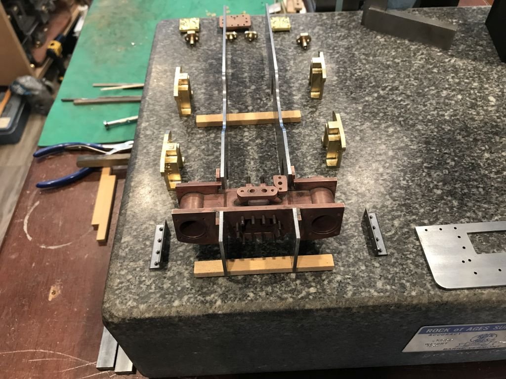
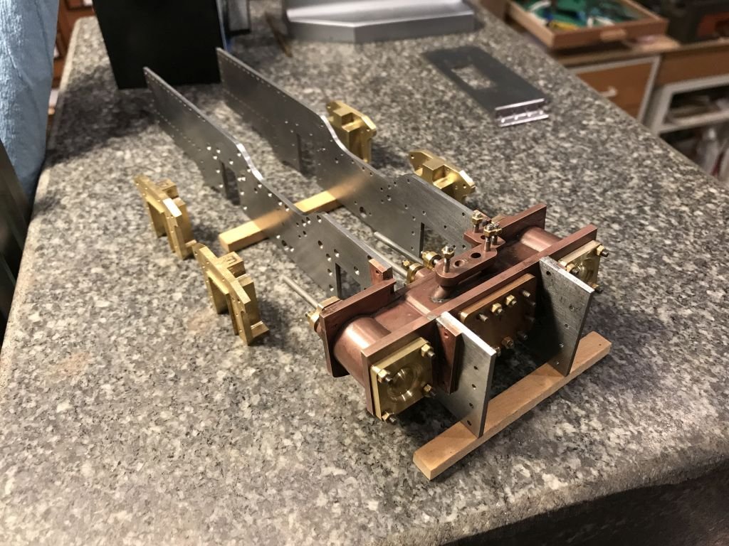
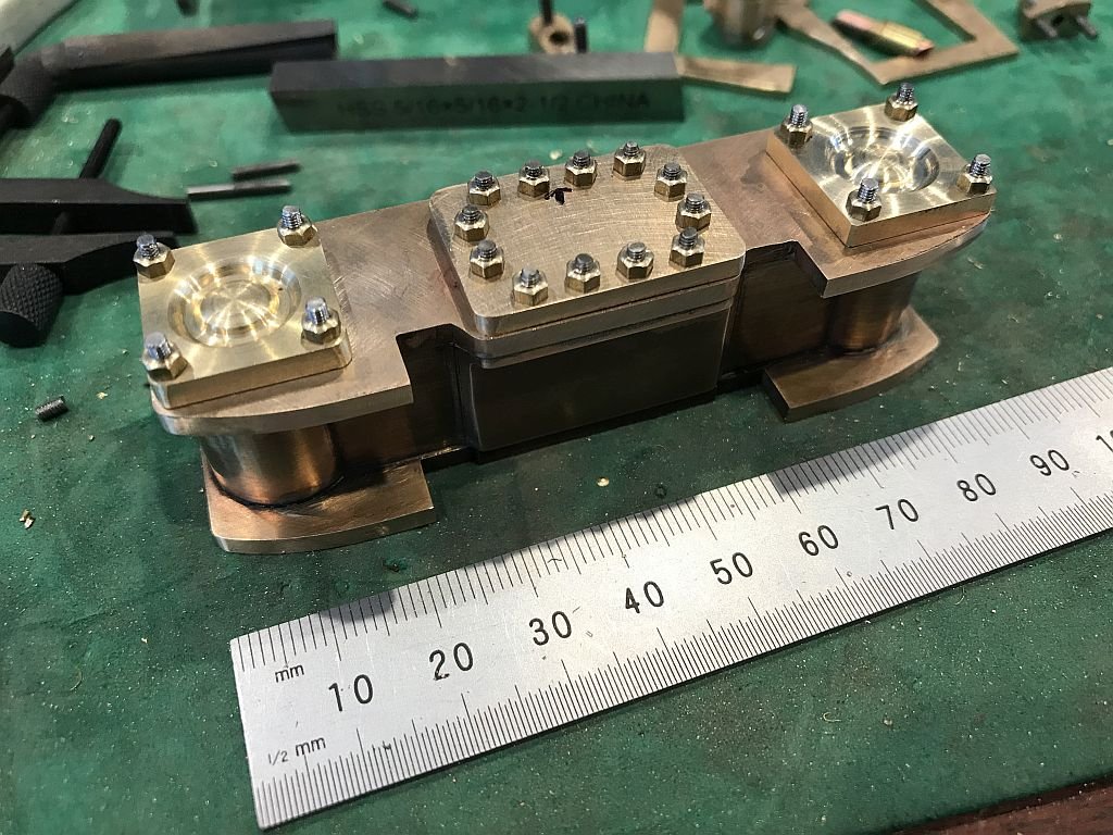
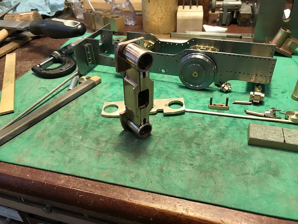
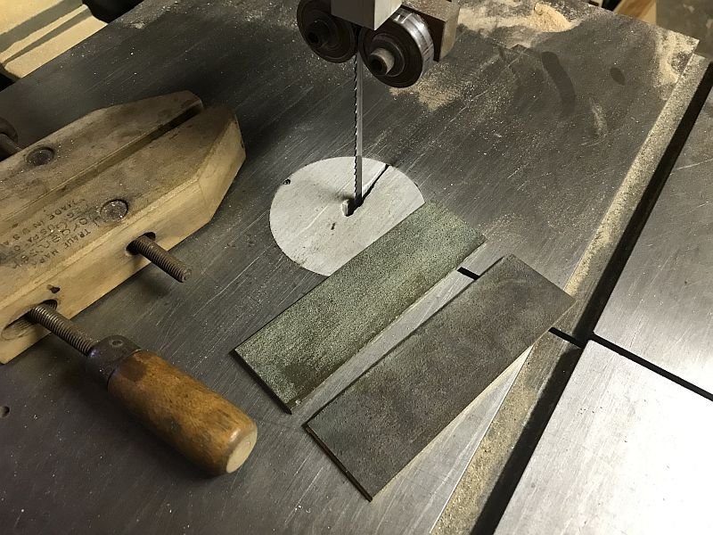
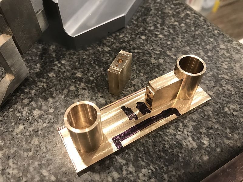
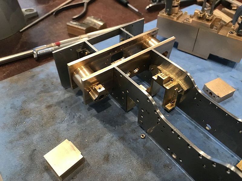
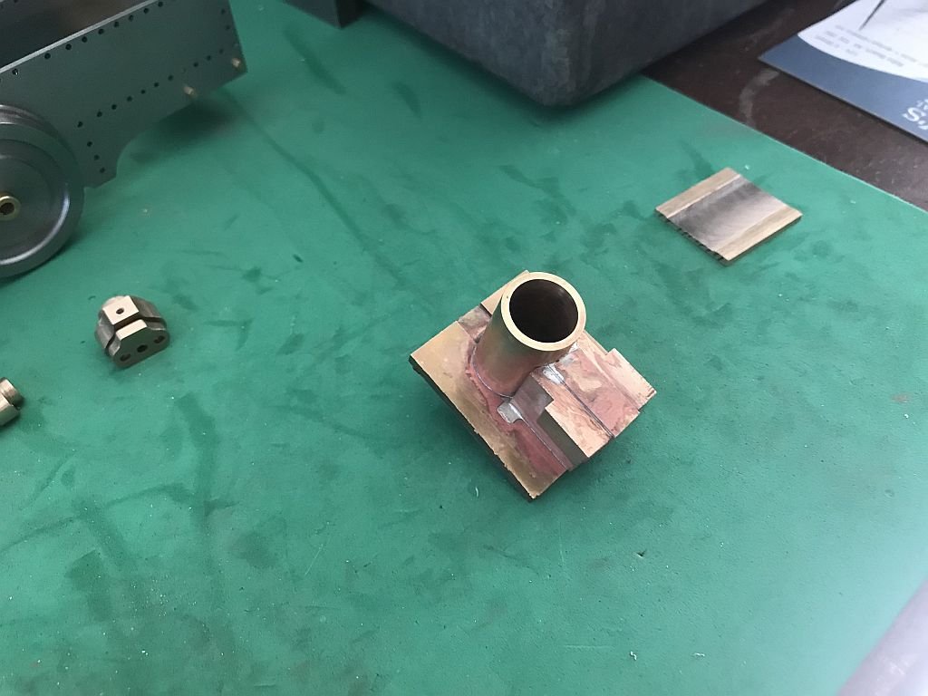
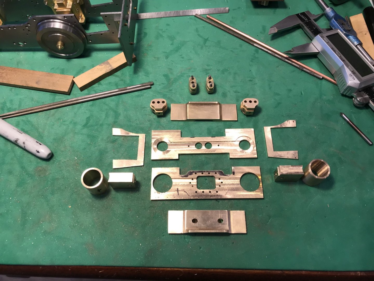
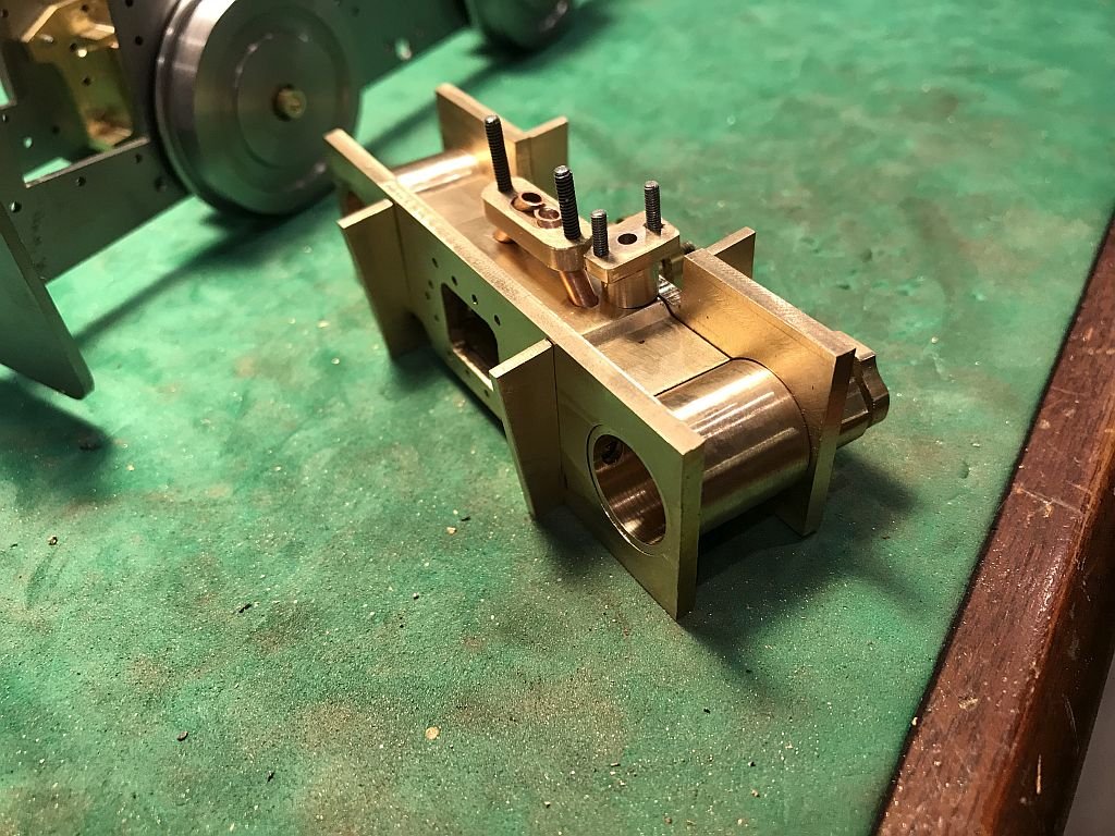
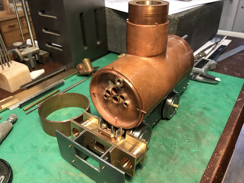
A lot of changes since the last entry. A complete rework of the cylinders to better reflect the way the casting looked on the full size loco. this entailed rethinking the whole procedure. First some more flat plate needed to be prepped I used the big bandsaw as this cuts through the brass and bronze like butter. After the plates were roughed out then the various internal elements were shaped and dry fitted, I wanted to get away from having the front gland bosses removable which of course meant having them fixed to the front plate with solder. I reworked the ones from the other set. Next the top and bottom plates that create the central common steam chamber were shaped because there are a number of large and small masses to be assembles and I am going to be using low pressure only 35psi I have decided to use a high temp soft solder (Worthington 97/3) it has a melting point of 229c or 444f and I will only be using saturated and not super-heated steam which at 35psi is 142c at the boiler (which will be completely silver soldered) So I did a test to see how well the Worthington solder flowed and also how it reacted to successive bits being added because I need to solder things together in a definite sequence. First i soldered the cylinder tube the front plate and the valve block together. The flux for the Worthington is the nicest cleanest flux I have ever used it is like the color and consistency of yogurt and is water soluble the solder capillaried beautifully and after popping the warm not hot block into clean water the part was clean and ready for the next addition. I added the front piston gland boss after cleaning that off I added the two side plates. I made the a bit heavier than the ones that will be on the actual cylinders. at first I put a clamp on the plates to ensure that they didn't move. The clamp fell of as soon as I started to heat up the assembly. Rather than fiddling with putting the clamp back on I proceeded to continue heating I had fluxed all the surfaces that were mating and put a small piece of solder into the corner where the plates and cylinder tube met one on each side. and one piece on each side at the top. As soon as the melt temperature was reached the solder flowed like water and capillaried through the new joints. I needed to replicate the same sequence that i will be using on the large assembly. This is a shot of the main components that form the new cylinder set. The c shaped flange plates do a nice job of holding the lot together while i have been making the various parts. All of the components to date including the exhaust flange and the steam inlet flange. which are tilted to the vertical by 6.108 degrees How it will look when the boiler is fitted but I cannot make the holes through to the smokebox until the cylinders are soldered together and the boiler support flange plates are fitted to the frames. Michael
- 96 replies
-
- 18
-
-
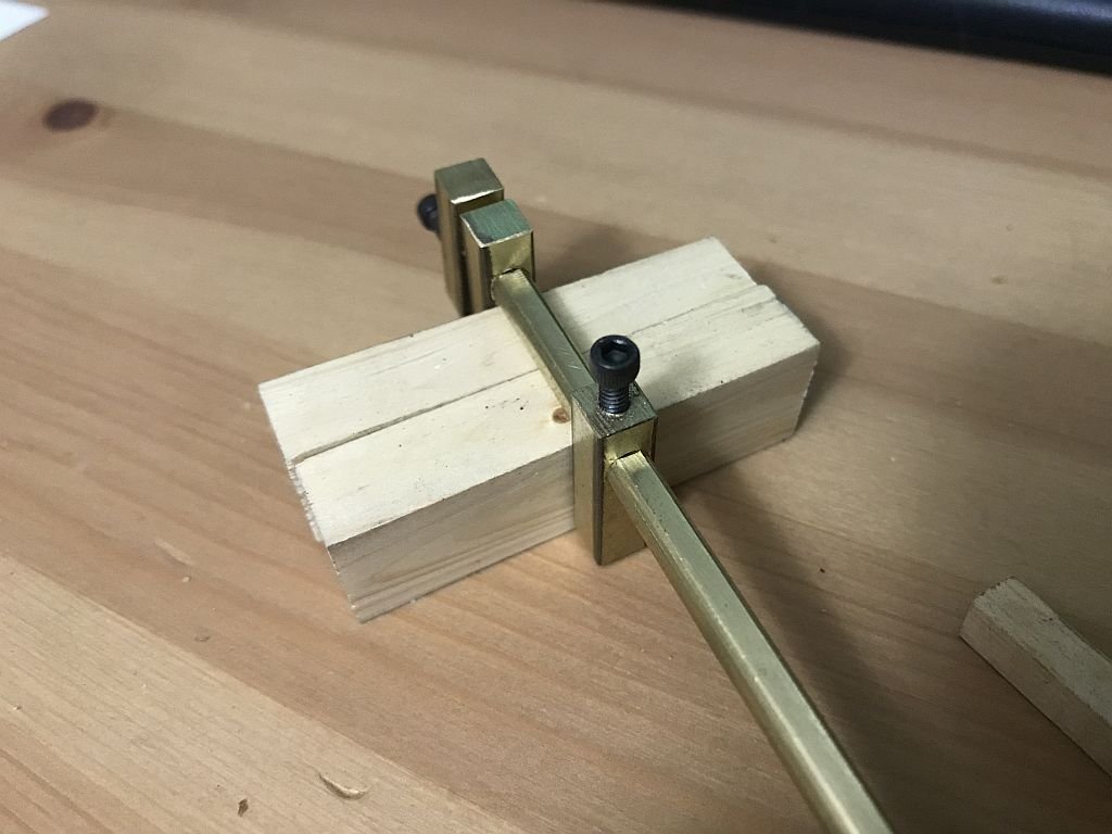
Hi Mark, The dimple was in the end of the brass bar I just cut the piece off the end not worrying about the aesthetics just whipped it up from stuff at hand. it took me about 40 minutes to make it the filing of the flat took the longest. I thought that round was more flexible for tight spots and the flat only so that the tightening screw did not cause the inevitable markings to cause the stop from sliding. With small clamps for the sorts of tasks that you illustrated with your planking and setting them through the portholes I should think that they would only need to be 3-4 inches in length max. [does the world really need another clamp design] I guess the principle of the bar clamp is really what it is, just a miniature version. It is interesting that as you had mentioned you had the clamps for a long time but this was the first time you had used them. I have seen those types of small brass clamps in a variety of different catalogues and always thought that I would like some but never actually got round to purchasing any. I should think that $24 for a pair of the brass bar clamps is in good competition with the miniature Irwin quick clamps which in my neck of the woods are around $24 each. I'll just sell the modified design for a cup of coffee☕ Michael
-
Hello Bedford, You have been busy, what a beautiful job you are doing on the model! looks like the same superb standard that you executed on the big one. Regarding the thin leather I eventually opted for some very thin commercial dress leather that was picked up at a thrift store it was a ladies leather skirt before I took it apart. michael
-
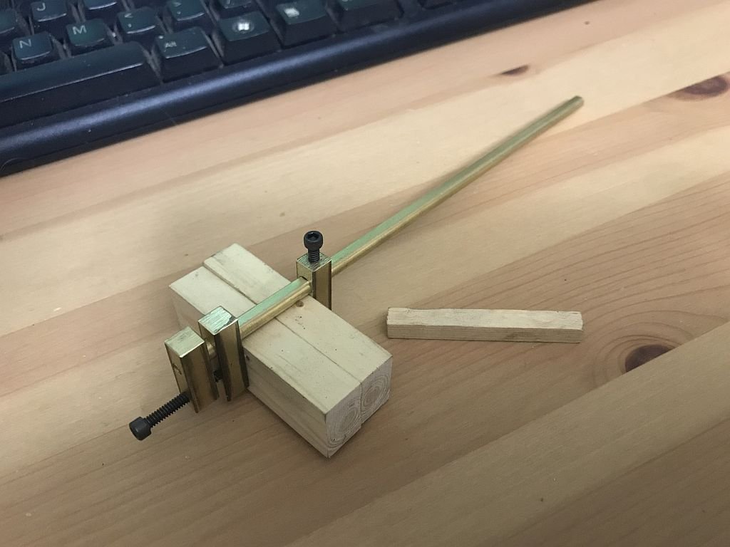
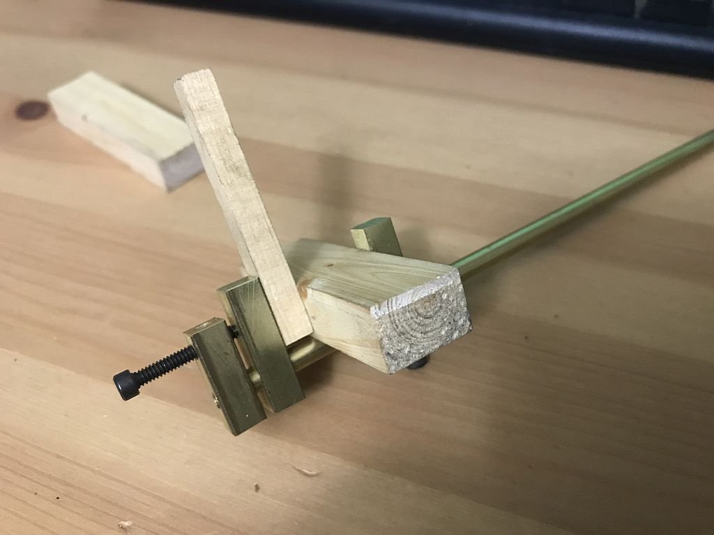
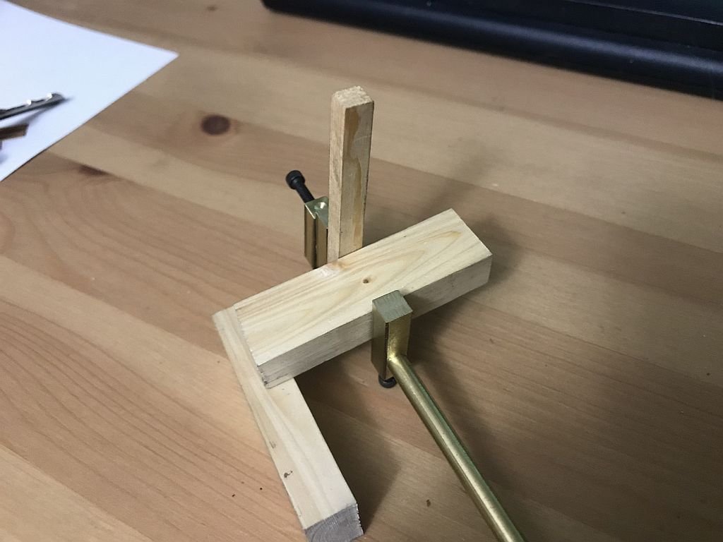
Ok I couldn't resist, I went out to the shop and with a couple of 4x40 allen head cap screws and a 6x32 threaded end on a bit of 3/16th brass rod filed a flat along the bottom side after locking it into the head end, and some 1/4 inch square brass bar sliders Very easy to make. Cheers Michael
-
Mark thinking about these clamps they would be easy enough to make with a round bar the 1/4 inch stuff that Home depot sells is nice brass easy to machine. my thought would be to mill or file a flat along the bottom for the screw to tighten against and use a couple of allen head machine screws, the jaws could be brass or aluminum. I will have to see about making myself a couple tomorrow. Michael
-
Hi Vaddoc your rope looks great. Regarding the copper crimps, yes they were just a bit of tube crimped with some pincer type pliers that had beed dulled so as not to cut but just crimp. Michael