


GAW
-
Posts
183 -
Joined
-
Last visited
Content Type
Profiles
Forums
Gallery
Events
Posts posted by GAW
-
-
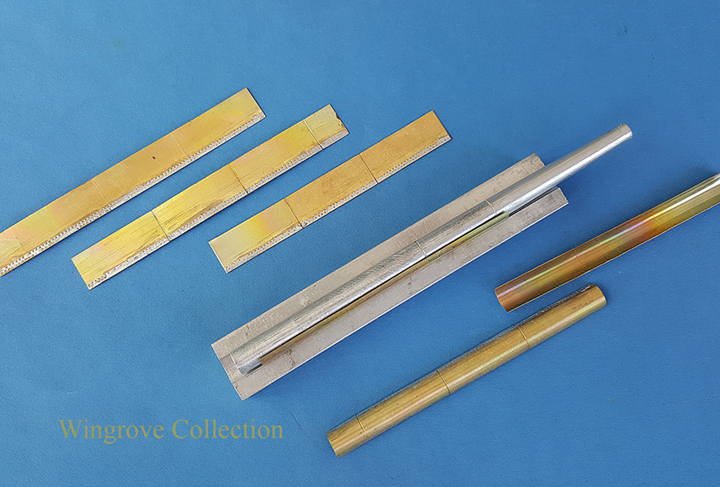
Fig-129 We now come to the masts, in this case just stump masts, as I wished to show the three angle iron ribs on the inside. Each is made up of a stepped series of three iron plate circling the mast and riveted together with a double rows of rivets, with the stiffening angle iron ribs running down the centre of each plate. All rivets would have been countersunk to maintain a smooth surface to the out side of the masts. To assist in their construction I machined a length of Aluminium rod to the inside diameter of the Masts, with a slight taper at each end to accomodate it where required, this then forming the Master Pattern. The final shape and size of each mast being determined by a series of aluminium rings, machined on the inside to match the required out side diameter of that part of the Mast. A small block of aluminium was also machined with a groove down the centre, to match the new Master Pattern. These then formed a male and female die, between which all of the mast plates could now be formed. Each plate was marked out and cut to size in threes, provided with the double row of rivets down each side, annealed, then cleaned and tinned before being pressed to shape between the pair of Dies.
-
August 2018
I seem to have missed a couple of points last month, brought up by observant visitors - my mistake on the name of the top most plating below the Bulwarks, it is of course the Sheerstrake, and not the Garboard Strake, which is the lowest plating next the Keel. With reference to the bar across the Freeing Port opening. I have never seen an illustration or photo of one on the inside, as the stays would be in the way. Those on the out side serves two purposes, to restrict the opening of the door, thus preventing the larger items, including seamen from passing out of it when the deck is emptying of water.
-
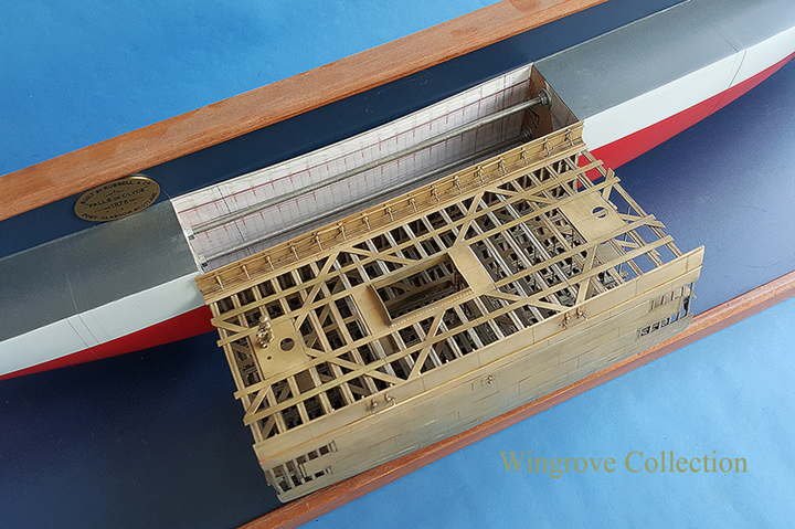
Fig-128 The main hatch now in place on the centre section of the model,. Later I added a leader down to the Tween Deck and on down into the Main Hold - not sure if it was originally there, but is at least a logical place to locate one and looks natural.
- JOUFF, FatFingers, druxey and 15 others
-
 18
18
-
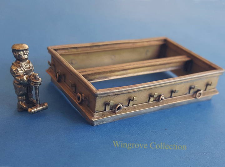
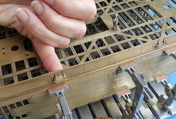
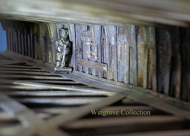
Fig-127 The angles brackets. rings and fittings are all fabricated from stock brass, and soft soldered in place to complete the single unit. This was then dropped into the hole between the Frames, from where the original sample came out and soft solider in it’s final resting place. Jock the Riveter is useful to have around, to keep the scale of things in view at all times.
-
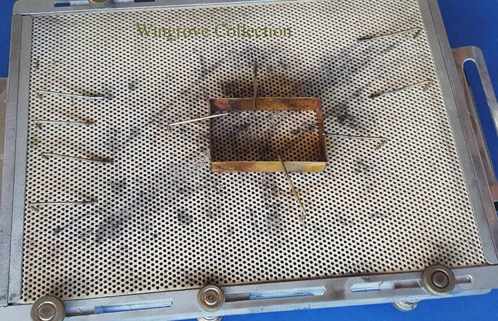
Fig-126 The main hatch I originally made up from brass sheet and angle, to the shape and size indicated on the original Ships Plans of 1878 - It was only later that I realised that this was not supposed to be a scale drawing of what was actually fitted, but more a symbolic indication of the size and the placing of the Hatch. For actual detail I used photo and data of the hatch as it is today, as I feel that it is most probably the original one. The rectangle shown here of fine sheet brass, being silver soldered together to form the sides of the new Main Hatch.
-
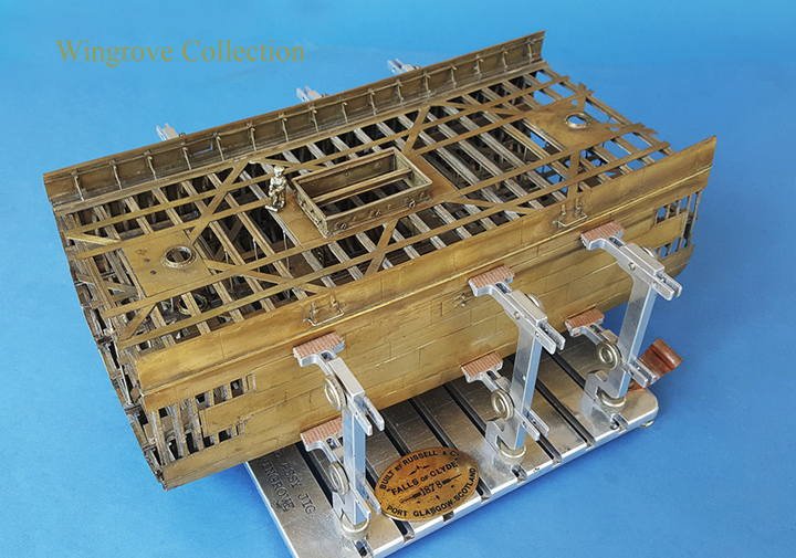
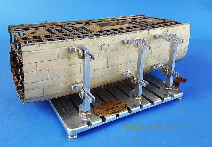
Fig-125 The now completed Hull centre section, ready for fitting out, but shown here along side the original Half Model, with the relevant Half Frames removed.
-
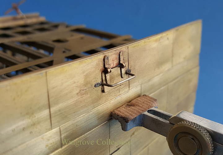
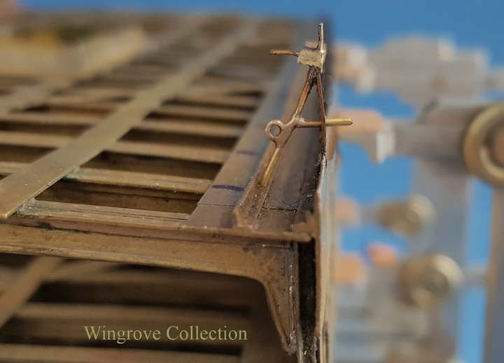
Fig-124 And yes the Freeing Ports do open with working hinges.
- paulsutcliffe, gjdale, Valeriy V and 12 others
-
15
-
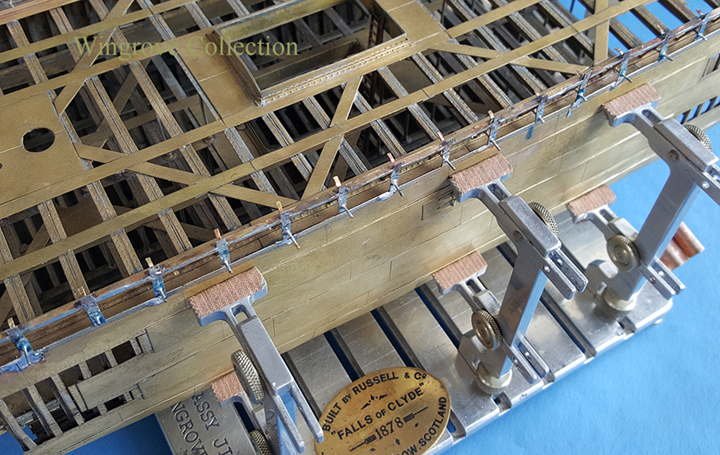
Fig-123 Freeing Port detail, all parts soft soldered with the resistance soldering unit, with the parts tinned first, fluxed, then heated while being held in place, with what ever is handy.
- Mike Y, hexnut, paulsutcliffe and 6 others
-
9
-
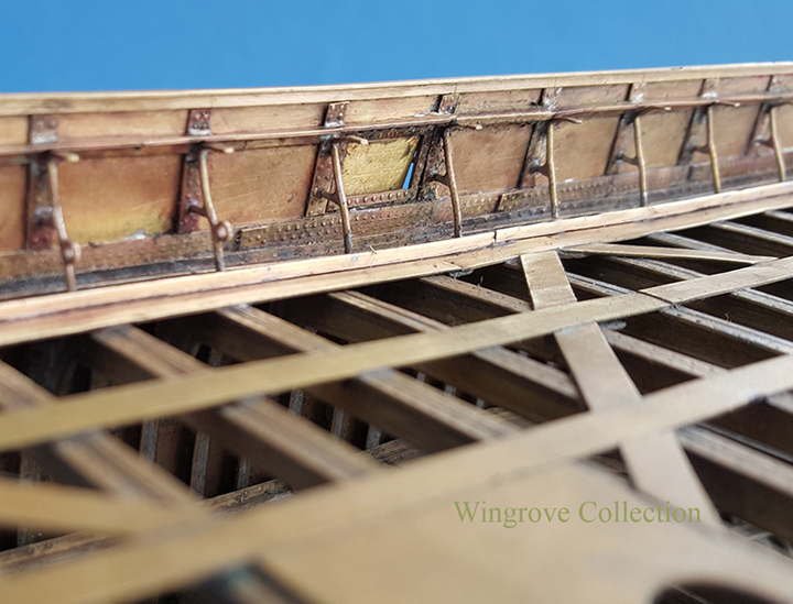
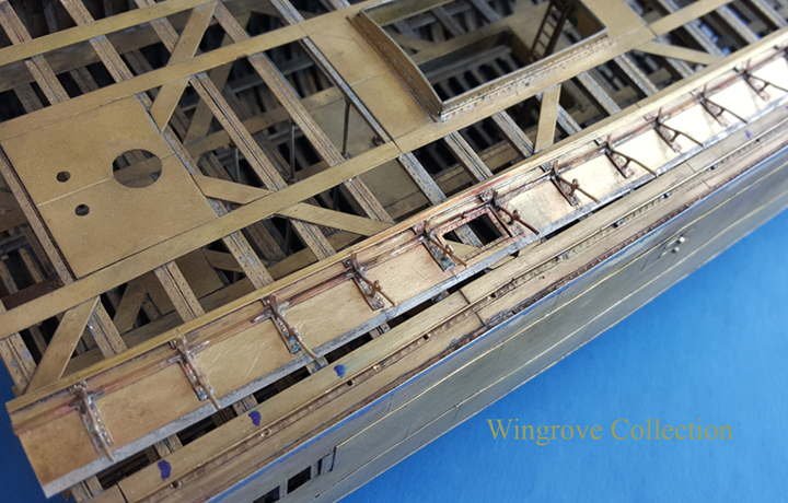
Fig-122 - The Stays, angle iron for the Main Rail and Topgallant Rail are now all soft soldered together and soft soldered to the top of the Garboard Strake, as seen from the inside.
- wefalck, oneslim, paulsutcliffe and 4 others
-
7
-
Fig-121 The Bulwark plating and Stays have now been soft solder together, this was spot soldered - for want of a better term - while the Stays were still temporally attached to the Garboard Strake, now they can be more firmly soldered together to form a single unit.
-
The tool is a diamond dust point of about 0.020”, would be better at half that size, but I have never seen them available. This is the one that came with the unit, together with a carbide?? point, that seemed to want to burn the wood rather than cut it. Having spent so my time making the tools, I wanted to press on with making the parts, so did not investigate further with what cutting tools might be available. The exercise was really to just mark out the parts for cutting and filing up to the finished shapes, and it worked perfectly, and as you will see much later down the line, accommodated all the polished wooden furniture on the Poop.
-
Those interested in the tooling side, will find another new tool shown on my News & Comments page
< http://www.wworkshop.net/Home_Page_/Home_Page.html > It will be covered in more detail there and here in due time when we get to that stage in the next and last of the Falls of Clyde models. I show it now just to whet appetites, and to show that there are answers out there for most problems - they just need a little more thought than going around to your corner store and picking it off the shelf. The problem here was how to carve ‘Falls of Clyde’ on the side of the wheel box at 96th scale. It took a month to complete that wheel and box, but the tooling created to get there will save half a year solving future problems.
- popeye the sailor, mtaylor, hexnut and 2 others
-
5
-
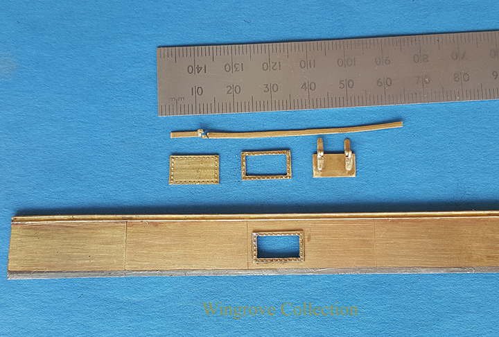
Fig-120 Before attaching the Bulwark plating to the Stays a couple of fittings needed to be added, namely two Freeing Ports on each side. It was more convenient to make and fit these to the plating, before attaching the Plating to the hull. Each of the Freeing Ports consisted of a frame, with rivet heads attached to the inside and a small plate door - Freeing Port - hinged from the top, made to fit an opening cut in the Bulwark Plating, between two adjacent Stays. .012” sheet brass was used for the doors - a little oversize, but less of a problem to work with on this size. The hinges being made of the same.
-
Fig-119 Here we see the length of Stays in place ready for the excess wires to be cut off. It was possible to make this as a single length and with the foot of each stay in it’s respective hole, and a spot of soft solder to attached alternate vertical plates to the top edge of the Garboard Strake, it was a simple matter to adjust the angle to match that required. Incidentally when making this part for the full length water line model of the Falls of Clyde - to be covered after the completion of this centre section - it was possible to have the full side of 38 Stays as a single length, to work with.
- Siggi52, JOUFF, popeye the sailor and 5 others
-
8
-
Fig-118 Before the Stays are made and at the point of setting their positions out to support the Bulwarks, a series of hole were drilled along the Waterway Angle Bar that forms the inside edge of the Scuppers to locate the foot of each of the Stays. In full size practice the foot of each Stay would have been provided with a small plate welded to it, so that the foot could be riveted at this point to he Waterway Angle Bar. With the vertical part of the Stay standing on the top edge of the Garboard Strake, the bottom part of the bar passing into the hole provided in the Waterway Angle Bar, the correct length of the horizontal portion of the Stay can now be ascertained. With the vertical part lined up with the Garboard Strake, the horizontal bar can now be soft soldered in place and the extension chopped off, flush with the out side.
-
May 2018
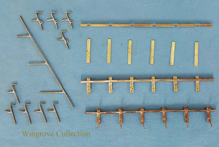
Fig-117 In Fig-115, I illustrate a method of making single Stays with a ring attached, here we see a way of making multiple Stays, the wire with three others silver soldered in place at the correct angles. These can then be chopped to length, have rings attached, and bent ready for fitting. On the right I show the several stages required. First a length of angled brass is notched to take the upright plates, that in full size practice is used to rivet the stay to the Bulwark Plating. These have to be exactly placed 5 feet (5/8”) apart, this I did with a 1/16” end mill on the milling machine. The strips of brass sheet, ready provided with a double row of rivet heads, are cut long and silver soldered to the angle brass, one to each slot, making sure that all are at right angles to the angle brass bar. I use silver solder here as the final joint of the Stay to each of these plates will be with soft solder. All that is needed now is to trim off the excess brass from each strip, above and below the brass angle bar, to the correct lengths, and drill a hole to take the horizontal bar from each of the Stays. Simple aluminium length gauges being used to mark each one for chopping or drilling. The lower assembly shows all the parts in place, however only the top of the Stay’s have been soft soldered in place at the point of the silver soldered joint of the vertical plates to the brass angles cross piece, the horizontal bar just being placed into it’s respective holes at this stage.
- popeye the sailor, wefalck, JOUFF and 2 others
-
5
-
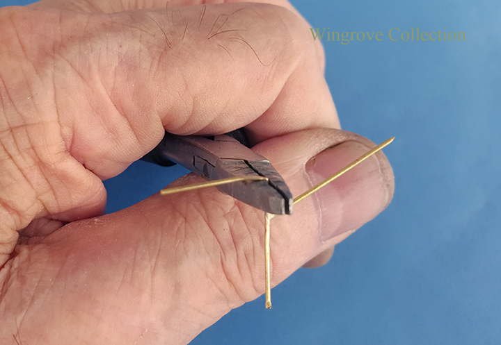
Fig-116 With so many Stays to make, and plenty of cheap pliers in the shops, well in Spain that is, for jobs like this, I purchase a spare set of pliers and grind them down to fit the task in hand. In this case to set the distance between the side arm and the top of the Stay, which is then bent, hammered flat and cut the length as required.
-
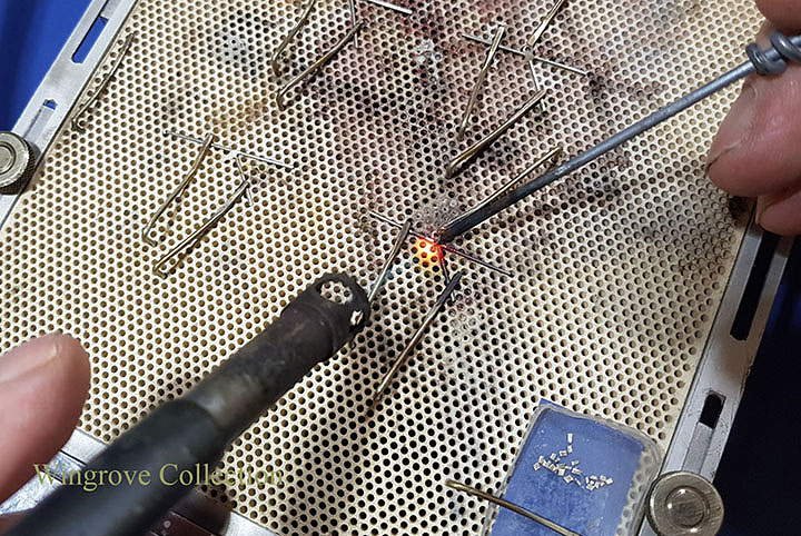
Fig-115- The Stays, all 76 of them are formed from .022” nickel silver wire - Why - because I had it in stock, the size was reasonably close, and nickel silver on this scale will take the silver soldering heat better than brass wire. Silver soldering because I wanted no breakages, once installed it would be very difficult to replace, and soft solder would be used for the installation , so would likely remelt this joint in the process.
The base for the silver soldering is the Platinum Ceramic plate. We first saw it back at Fig-30 of making the Bulb Iron, and is the ideal base for this work. Bent wire pins - called Dogs - again I use nickel silver wire for these - are used to hold the parts together, by just pressing one end into the hole provided, the other end holding down the parts in place. There is a trick to silver soldering on this scale. First the use of reflected heat, do not play the flame directly onto the part to be heated, but play it only on the Ceramic plate close by and heat slowly. Then do not apply the silver solder from the end of a silver solder rod, or you will likely get a large blob of it on the joint. Rather hammer flat the end of the silver solder rod until it is very thin, then cut it into very small grains. Take a length of iron or steel fencing wire and make a handle on one end, file the other to a point. Put this in a flame and bring it up to red heat and blue/black with oxide, now touch the end to a file to brighten a tiny flat. Dip this in the flux, pick up a grain of silver solder on the tip and apply this to the heated joint. Some of the silver solder will remain on the point of the iron/steel pick-up tool, but a tiny amount will complete the joint. The grains can be seen in the small blue tray at the bottom right. I found that one of these grains would be sufficient to complete one, two or three joints, with what remained on the end of the application wire.
-
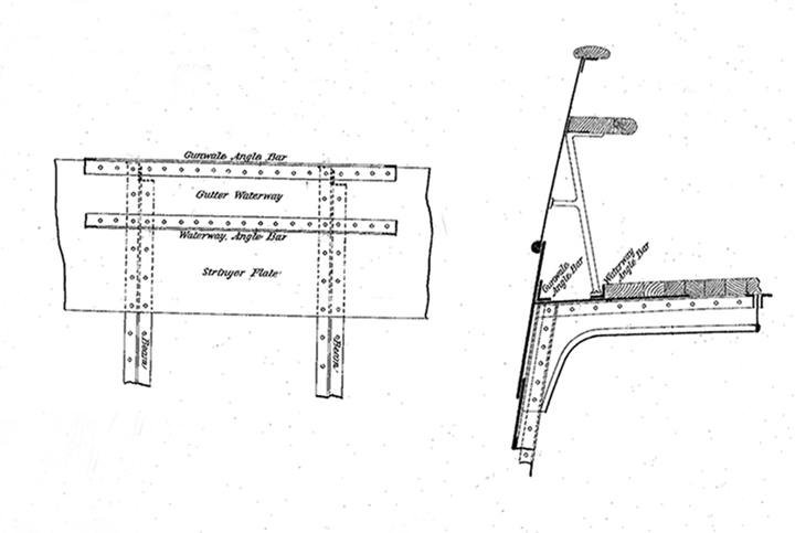
Fig-114- A copy of a technical draft of the period to show how it was done. This is almost identical with the Falls of Clyde, excepting that the Garboard Strake of plating is shown as an ‘OUT’ plate, while on the Falls of Clyde it in an ’IN’ plate, being overlapped by the one below. These are the points to look out for with iron ship construction. The practice will be the same, but the detail may vary.
-
On the Falls of Clyde there are 38 Bulwark Stays on each side. The top of each is flattened and bent horizontally to carry the main rail, that is also supported by an angle iron bar running along the top of the Stays and riveted to the Bulwark Plating. Above this is another section of angle iron, to carry the top rail both being originally of hardwood, most probably teak but are now gone.
The Stays are placed five feet apart and do not match the Frames, that are two feet apart, or rather the deck beams that are attached to alternate frames, at four feet apart. It took me some time to work that one out, as I could not believe they differed from the frames. However I had a friend check it out and that was the result. Why it should be so, I have no idea, unless it was to keep the costs down, why add more if this spacing will do the job in question. One problem became apparent here, in that the original board room painting of the Falls of Clyde, a copy of which I have, clearly shows that the rectangles between the Stays - large at the bottom and a thin strip at the top - were painted white, while the stays and the uprights that attaches them to the Bulwarks were painted mast colour. That is 78 tiny rectangles per side all to look perfectly square, exactly the same, neat and tidy, and that with the rigging bars in front of them at each mast station. As this model was not to be painted but left in a raw iron finish, it was a problem to leave for another day, namely for the fully rigged waterline model - and a simple solution was found by the time I had started that, the last of the three models. More later on that one.
- druxey, hexnut and popeye the sailor
-
3
-
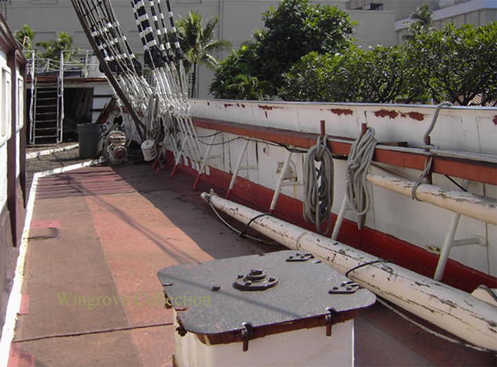
Fig-113- We now come to the Bulwarks, the ships plating above the main deck, along each side between the Forecastle and the Poop. The supporting Stays are made up of welded iron bar and plate riveted to the Bulwark plating and to an angle iron bar riveted to the deck stringer along each side of the deck, called the Waterway Angle Bar. The deck planking abuts to one side of this, while the other side is filled with cement, hollowed out in the centre to form a Gutter Waterway for the water washing off the deck, and is more commonly know as the ‘Scuppers’. The photo is of the Falls of Clyde main deck, taken in 2005. the item in the foreground being one of the access points to the side oil tanks. I did attempt to get down inside to photo the inside of the plating and the loading port door at this point, but the ladders were almost totally rusted away, so waited for the surveyors to put down temporary ladders and take the photos for me.
-
April 2018
—————
Thank you for your comments, always pleased to have them, complimentary or otherwise - The finish will be a simulated iron, before the rust get’s to it - more on that when we get there.
As you are all ship enthusiasts, you might find of interest another ship modellers work featured on my web site this month,
< http://www.wworkshop.net/Model_Makers_Showcase/Galler-2.html >
He may be known to some of you for his past work, as Bruce was the one to introduce me to this web site and recommended my Current Log of the Falls of Clyde. I like his work immensely and am please to add it to my web site
- popeye the sailor, mtaylor and druxey
-
3
-
Fig-112 - A view of the out side - Hull plating complete - now for the Bulwarks
-
Falls of Clyde 1878 by GAW - FINISHED - scale 1:96 - iron 40-frame hull center cross-section
in - Build logs for subjects built 1851 - 1900
Posted
Fig-130 To assemble the parts, the first three rows - nine plates - were adjusted around the Master Pattern and held in place with the aluminium rings, then heated at strategic spots to melt the tinning solder to hold them in place, sufficient to withdraw the aluminium Pattern, after which further heating with the resistance soldering unit was sufficient to completed the exercise.