


GAW
-
Posts
183 -
Joined
-
Last visited
Content Type
Profiles
Forums
Gallery
Events
Posts posted by GAW
-
-
January 2019
Wishing you all a happy, healthy & wealthy 2019, may it exceed your wildest dreams.
------------
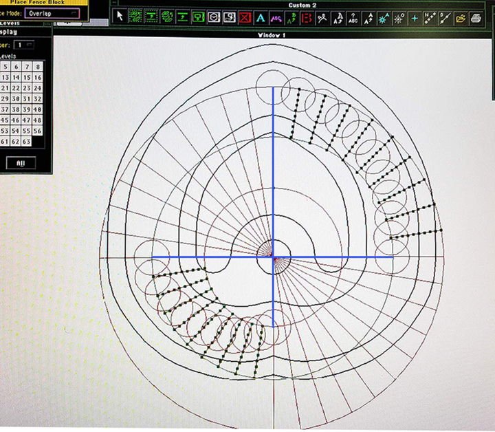
Fig-149 - In the original drafts for the pump, large cross arms are shown at the top, and also atop the inverted heart shape cam. Checking out the draft for a scale, it became obvious that it was in fact not drawn to scale, however the arms if incorporated would not fit the space available for the Bilge Pumps on any scale. It soon became clear that with the heart shaped cam, the top arm was superfluous and not needed at all, but how come that shape for the cam. With a CAD package and my trusty Mac, it did not take long to discover the secret, just by plotting the movement of the parts, when rotated at different points, and there it was the heart shaped cam. I became so fascinated with it, that I decided there and then to make two models of the pump - one at 96th scale for the Falls of Clyde model and one at 1/4” to the foot, as a working mechanism - not I might say as a working pump, but just to show/see how the cams worked in practice.
-
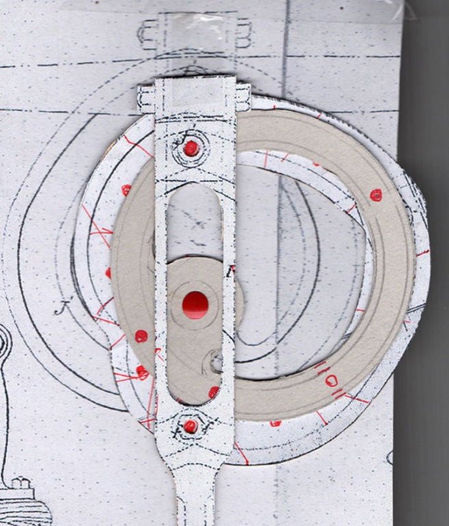
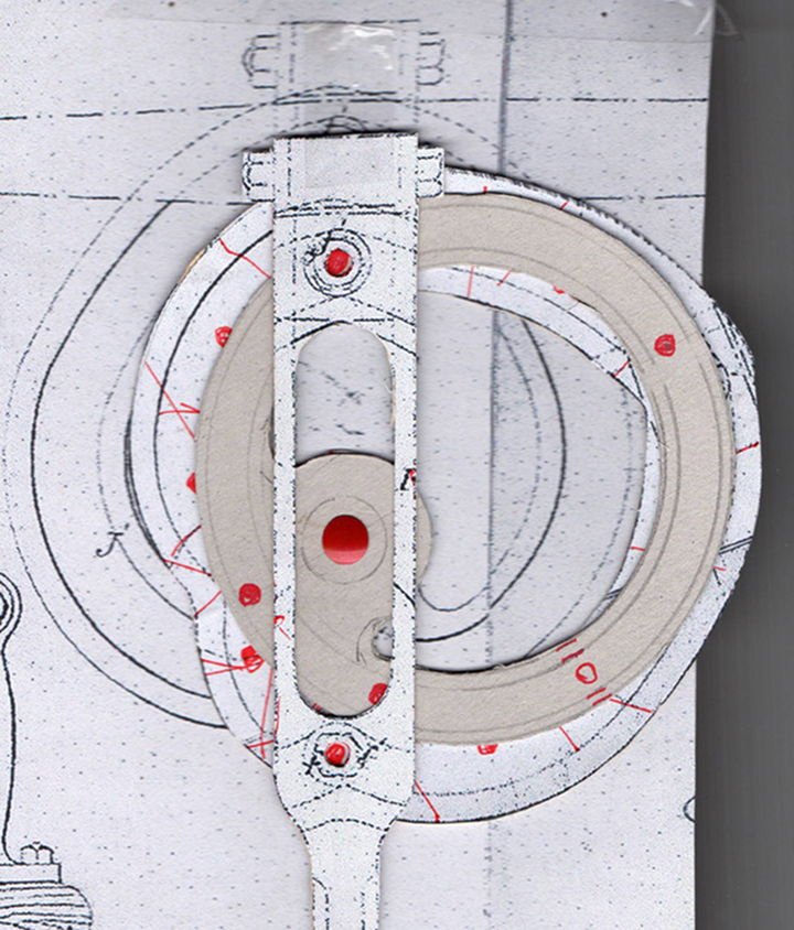
Fig-148 After some experimentation with the cardboard cut out and drawing pins as pivot points, I eventually got the gist of what it was all about, and actually made a card board model of the mechanism that would move the connecting rod vertically up and down, with no sideways movement at all. The next question was how to make it in metal, as this was precision engineering to a very high order, in fact so high that I needed a CNC machine to solve the problems - which begs the question how did they make this in 1878 - I still do not have the answer to that one. Perhaps when we see the complete mechanism working, some one will come up with an answer to that one as well.
-
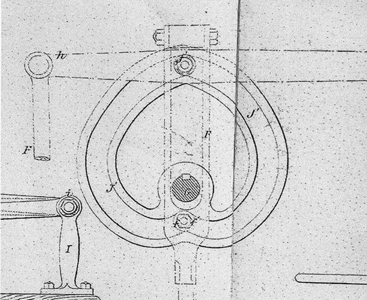
Fig-147 However this draft was also included, almost as an afterthought, as this was the only view shown, while there were three views shown of the extended arm arrangement. The original notes with the draft does not appear to have survived so it was a case of working things out for ones self and why the inverted heart shape?
-
Fig-146 In 1869 Wallace & Crawford were issued with Patent 2763 for the invention of “improvements is pumps and mechanism ……….”, further research turned up a copy of the original drawings part of which is shown here. Basically this consisted of four pumps side by side, and operated by cams in place of a crankshaft. One needs to understand the problems associated with pumps in general. What in a petrol engine is the piston, in the pump is a cup with a valve in the centre and has to remain vertical in the cylinder in it’s movement. In a piston engine with a crank shaft, there is a pivot in the piston so that the connecting rod can move side to side as the crank shafts turns. This is not possible in a pump as the valve takes the place of the pivot pin in the piston, and several ways were devised in the pumps of the period to maintain the vertical moment of the cup, while allowing the connecting rod to pivot according to the crankshaft. It would appear that there were two aims with the new pump design, the first was to have four pumps in the same space as the two, and find a better way of maintaining the vertical movement of the cup and valve.
In the main draft we have a series of pivoted arms and small cams to lift the cup and valve, but on close examination, they would only work to lift the cup, and I cannot see how it could force the cup back down.
- Landrotten Highlander, jud, druxey and 4 others
-
 7
7
-
Fig-145 The Bilge Pumps shown here are those of the Star of India, and are typical of all that I have ever seen and photographed, note that the elongated shape of the two pumps is fore and aft, which again is typical of those fitted to the Windjammers of the late 1800s. Note also that there are just two pistons or rather pumps on a single crankshaft and that probably forged in the blacksmiths shop. If so made, it would have been very difficult to forge it to take 4 pumps in the restrictive space between the Fife Rails and between the mast and the deck house that is the usual location of the Bilge Pumps. In later times, the pumps were made as double acting, but at this date I do not think that it was so.
The Falls of Clyde was the first of the Falls Line fleet of iron four masted ships and barques built on the Clyde, and this just three years after the very first of the new breed, this being the County of Peebles, so we are in a period of innovation , a new concept of ship design to compete with the ever advancing Steam Ship. So we can expect the pumps to be of advanced design, and indeed they were. Now began the search, luckily the original costs book for Hull-17 (Falls of Clyde) is still with us, and this lists the Bilge Pumps as manufactured and supplied by R.C. Wallace & Co with an address as Glasgow. Further research in the Post-Office Annual Glasgow Directory for 1878/79 identified the company with an actual address, yet further research revealed two more companies associated with the pumps R.C.Wallace & Sons, and Wallace and Crawford, in fact the Wallace and the Crawford families were closely involved with each other way back in history, and that his initials R. C. stands for Robert Crawford Wallace.

-
There is always hope Sailor1234567890, the latest is that she will be home in March 2019 - If you wish to help save the old lady monetarily or otherwise, drop a line to < savefallsofclyde@gmail.com > they will be pleased to hear from you - Remember she will be 140 years old on the 12th of December -too good to lose at this late hour, she must be saved and brought back to her birth place in Glasgow and not sunk as a divers wreck off Honolulu.
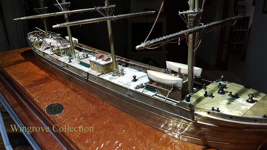
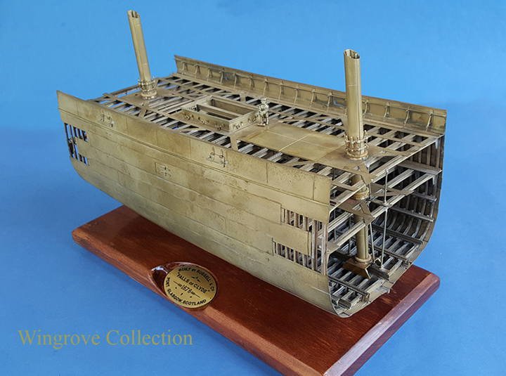
For those interested in my third and final model of her, I have here included a shot of progress todate - this is now being covered as the ‘Current Project’ on my web site, and may be covered here in further detail, if requested after this one finishes - it shows her as originally built from the scant details still with us.

-
On 10/30/2018 at 10:14 PM, michaelpsutton2 said:
Your machine work is amazing. I do not think I have seen you equal working in metals on this site. Do you know where there are more complete plans for this vessel. The Historic American Engineering Record one are rather incomplete.
There are no complete plans available that I know of for the Falls of Clyde, just an odd sheet here and there, I did have ideas many years ago to draft a set and write a book on her history and the building of the models - time will tell if I ever get around to it - thanks for your interest - do not forget that the building of the third and final waterline model, is the Current Project here < www.wworkshop.net > Happy modelling.
- Jorge Diaz O, druxey, mtaylor and 1 other
-
4
-
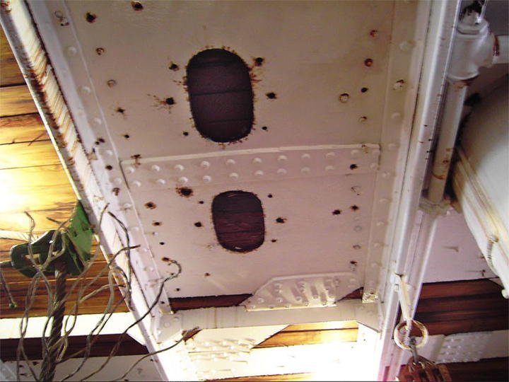
Fig-144 A photo showing the same holes in the deck plating of the actual full size Falls of Clyde. The Bilge Pumps were removed in 1912, when she was fitted out with internal tanks, as a sailing oil tanker, but luckily the deck plates were left intact to indicate the type of pumps originally fitted - There are no photographs of what these original pumps looked like, and until I manages to dig up the original data, with the help of the staff of the University of Glasgow Archive department, no one had any ideas about them, other than they must have been quite unusual. I have visited almost all of the old Windjammers that still sail the seas, and a lot of those tied up as Museum ships, and in all cases, the elongated holes to take the Bilge Pumps have been positioned fore and aft, and not across the deck. Thus stated a very interesting search - find and reconstruction - but for next month.
-
-
Fig-142 The completed Midship house in place with Jock the riveter there to check the scale.

-
November 2018
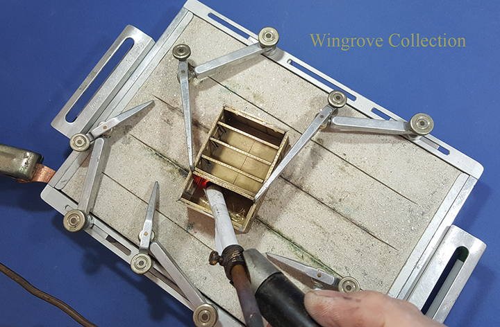
Fig-141 The midship House frame work of angle iron - brass - is first tinned then located to the individual positions, one at a time, and heated with he carbon rod to melt the soft solder to attached it in place. Note that paper wrapped around the carbon rod to insulate it from the side of the deck house. This was a problem in the early stages, as contact with the rod will cause it to heat up and melt anything close by. But a small sheet of paper rapped around it and held in place with Cellotape was all that was needed to solve the problem.
-
Thank you folks, pleased to have your interest.
-
For those interested in the Falls of Clyde as a subject, my third model of it - the fully detailed Water Line model, may find my web site of interest for October, it being the start of it as my ‘Current Project’ - see also ‘News & Comments’ for more details on the subject < http://www.geraldwingrove.com/Home_Page./Home_Page.html >
-
News on the actual Falls of Clyde last week was that she is now scheduled to be picked up by a heavy lift ship in Honolulu on the 2nd of February next year to arrive back in Scotland on the 23rd, for a full restoration, but I will believe it when I see it - at least she has not been sunk as a divers wreck yet - I live in hope, having saved her from that fate twice.
-
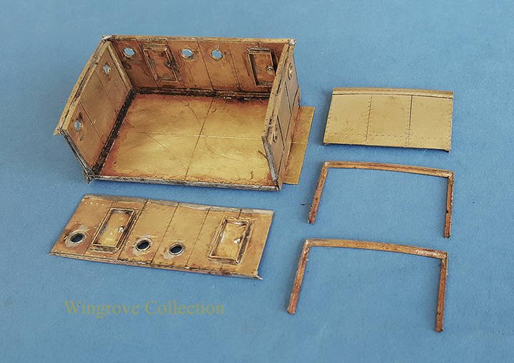
Fig-140 The completed side panels are here shown being assembled with soft solder to the base plate, after which the frames are added, and soft soldered in place. This is the midship house which at this period contained the Galley and crews quarters. The Galley was later relocated and a donkey engine and boiler put in it’s place, and is still there to this day.
- Jorge Diaz O, druxey, EdT and 10 others
-
13
-
-
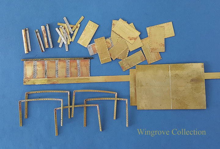
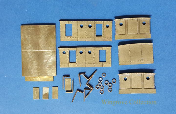
Fig-138 The next up is the Deck House, basically an iron box, here fabricated in .010 sheet brass - that is 1” thick sheet iron, obviously way out of scale, but more practical to use on this scale for this item. the sheets are cut to size and provided with rivet heads, these being visible on the inside, which with the top left off, are visible on the model. The mitred joints on the angle brass are silver soldered, while the remaining assembly is soft soldered together.
-
-
Fig-136 Stub Jigger Mast, with base platform, rings and wedging. The wedges were about 20 in number, difficult to count with out a good brushing off of the rust flakes - forgot to take a brush with me. On the model I have made them as box wood rings, and marked off the individual wedges with pencil lines. In practice you would not see the wedges as they would have been covered with a sail cloth cover, called a Mast Coat. Note three rings and wedges on the Jigger mast, for the Poop Deck, the Main Deck and the Keelson base.
-
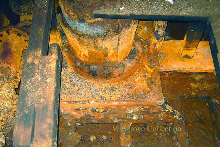
Fig-135 Base of the Fore Mast on the Falls of Clyde - a rather sorry sight, but with enough parts still recognisable to be able to make a reasonable representation of it on the model. Basically an iron platform over the Keelson with the side plates straddling four Frames, three visible the fourth under the rubbish on the left. The base of the mast is sitting in a ring riveted to the base plate, complete with wooden wedging. I was only able to access the base of the fore and Jigger Masts, the latter being under 3 feet of water at the time, which just left this one for the detail.
-
Fig-134 Turning the parts for the spider bands, all were made in brass and silver soldered together, then cleaned up with files, to fit their position on the masts. Once in position they were then soft soldered in place.
-
September 2018
Fig-133 There really is no excuse for model makers to get the scale of detail out of proportion on their models, if they can get to an actual ship. Even with out any regular measuring devise, have your good lady or a regular friend stand by the detail and snap a photos. I was looking here for the hight of the rings on the mast, but it is good for almost anything. A foot on a deck plank to the hight of the captains cabin and everything in between, I have been very lucky to have visited the Falls of Clyde four times, the last time on 2005 then taking over 800 photos. But most ships of a given period of a similar size will have general gear of similar dimensions. The next best thing if you cannot get there is to search the internet for photos - almost everything is on the internet- there are thousands of archive photos available at the click of a mouse , showing people on decks of all periods where cameras were available, many group/crew shots, where one can get a general idea of the build of an individual from the others around him and ascertain the hight if this railing or that bollard.

-
Fig-132 Showing two stub masts, one fitted with the stiffening ribs on the inside. The angle iron (brass) ribs were only able to be soldered in place at the extreme ends of the Masts, as it was impossible to get the carbon rod very far down the inside of the mast, with out breaking most of the other soft soldered joints, holding it all together. Which begs the question, of how in 1878, did they riven these plates together, and then rivet the stiffening bars down the inside as well. I have asked this question around among those of an age and in the service. One answer I came up with from several quarters, was that they would send a boy - down-the-tube - to assist from the inside. Although this might conceivably have been possible with the large diameter Masts, it does not answer the same question for the smaller diameter yards, that were also constructed of riveted iron plates. Perhaps we will never know, as with so many things of by-gone days, now all but forgotten with the passing generations.
-
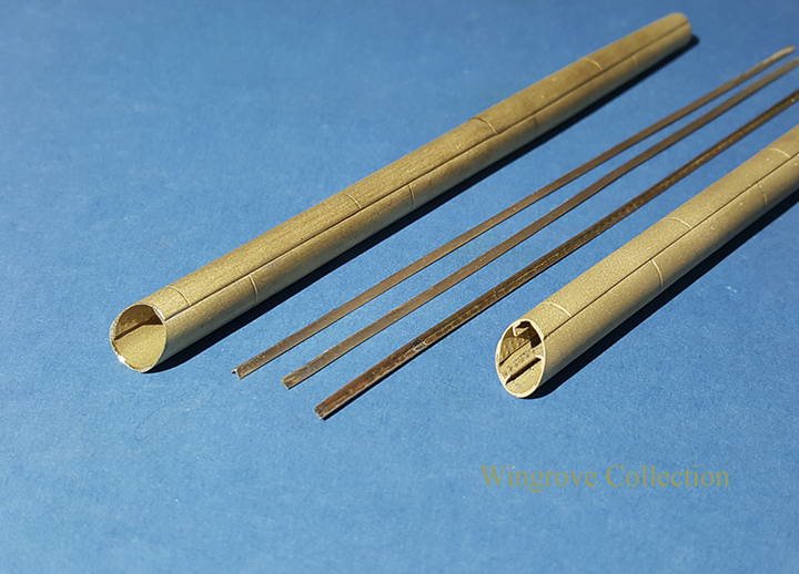
Fig-131 - The remaining plates were then assembled in the same way and attached to the first set, ends cut and trimmed to length - the aluminium rings being used to locate, adjust and fix their positions before the tinning solders were remelted, to complete the joints.

Falls of Clyde 1878 by GAW - FINISHED - scale 1:96 - iron 40-frame hull center cross-section
in - Build logs for subjects built 1851 - 1900
Posted
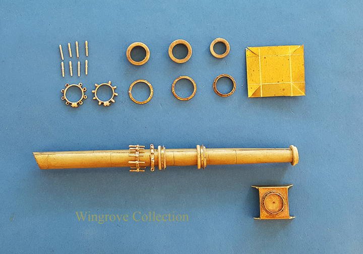
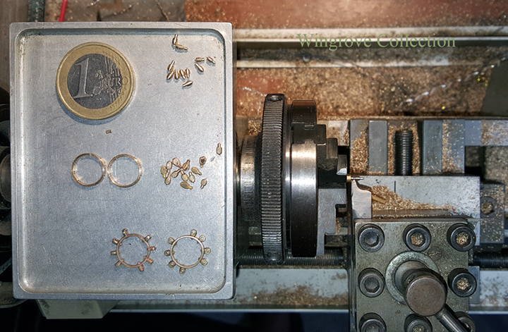
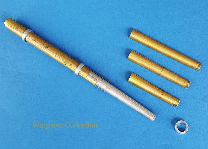
Fig-150 - I photocopied the drafts and printed them to a reasonable scale size, using the hight of the Fife Rail as the most logical starting point. This would determine the diameter of the fly wheel, and the hight of the main drive shaft. This in turn would determine the space between that and the deck, to be divided between the hight of the pump case and the maximum size of the cam. The size of the cam would then determine the maximum possible movement of the pump piston/cup. With these now determined a few sketches were made with dimensions and diameters noted and the parts turned up for the two pumps. Here can be seen the basic parts directly from the lathe.